EP2664553A2 - Procédé dýinsertion de produits individuels dans des récipients dans une suite de robots - Google Patents
Procédé dýinsertion de produits individuels dans des récipients dans une suite de robots Download PDFInfo
- Publication number
- EP2664553A2 EP2664553A2 EP12191048.3A EP12191048A EP2664553A2 EP 2664553 A2 EP2664553 A2 EP 2664553A2 EP 12191048 A EP12191048 A EP 12191048A EP 2664553 A2 EP2664553 A2 EP 2664553A2
- Authority
- EP
- European Patent Office
- Prior art keywords
- container
- product
- individual products
- band
- containers
- Prior art date
- Legal status (The legal status is an assumption and is not a legal conclusion. Google has not performed a legal analysis and makes no representation as to the accuracy of the status listed.)
- Granted
Links
- 238000000034 method Methods 0.000 title claims abstract description 37
- 238000011049 filling Methods 0.000 claims description 51
- 238000006243 chemical reaction Methods 0.000 claims description 38
- 238000012546 transfer Methods 0.000 claims description 29
- 238000004519 manufacturing process Methods 0.000 claims description 20
- 238000011144 upstream manufacturing Methods 0.000 claims description 17
- 238000009826 distribution Methods 0.000 claims description 9
- 238000003780 insertion Methods 0.000 claims description 5
- 230000037431 insertion Effects 0.000 claims description 5
- 230000005540 biological transmission Effects 0.000 claims description 3
- 238000003856 thermoforming Methods 0.000 description 10
- 230000006870 function Effects 0.000 description 8
- 238000004806 packaging method and process Methods 0.000 description 8
- 238000005457 optimization Methods 0.000 description 6
- 238000003860 storage Methods 0.000 description 6
- 239000005022 packaging material Substances 0.000 description 5
- 238000012545 processing Methods 0.000 description 5
- 238000006073 displacement reaction Methods 0.000 description 4
- 230000008569 process Effects 0.000 description 4
- 238000005303 weighing Methods 0.000 description 4
- 230000008859 change Effects 0.000 description 3
- 238000001816 cooling Methods 0.000 description 3
- 125000004122 cyclic group Chemical group 0.000 description 3
- 244000299461 Theobroma cacao Species 0.000 description 2
- 235000019219 chocolate Nutrition 0.000 description 2
- 238000005520 cutting process Methods 0.000 description 2
- 238000013461 design Methods 0.000 description 2
- 230000001788 irregular Effects 0.000 description 2
- 238000002372 labelling Methods 0.000 description 2
- 235000013372 meat Nutrition 0.000 description 2
- 230000003287 optical effect Effects 0.000 description 2
- 244000144977 poultry Species 0.000 description 2
- 230000009467 reduction Effects 0.000 description 2
- 238000007789 sealing Methods 0.000 description 2
- 241000196324 Embryophyta Species 0.000 description 1
- 230000004913 activation Effects 0.000 description 1
- 230000006978 adaptation Effects 0.000 description 1
- 235000015895 biscuits Nutrition 0.000 description 1
- 238000005266 casting Methods 0.000 description 1
- 238000012937 correction Methods 0.000 description 1
- 230000008878 coupling Effects 0.000 description 1
- 238000010168 coupling process Methods 0.000 description 1
- 238000005859 coupling reaction Methods 0.000 description 1
- 238000000151 deposition Methods 0.000 description 1
- 238000001514 detection method Methods 0.000 description 1
- 235000013305 food Nutrition 0.000 description 1
- 230000006872 improvement Effects 0.000 description 1
- 238000012432 intermediate storage Methods 0.000 description 1
- 239000007788 liquid Substances 0.000 description 1
- 238000005259 measurement Methods 0.000 description 1
- NJPPVKZQTLUDBO-UHFFFAOYSA-N novaluron Chemical compound C1=C(Cl)C(OC(F)(F)C(OC(F)(F)F)F)=CC=C1NC(=O)NC(=O)C1=C(F)C=CC=C1F NJPPVKZQTLUDBO-UHFFFAOYSA-N 0.000 description 1
- 238000007639 printing Methods 0.000 description 1
- 230000000717 retained effect Effects 0.000 description 1
- 238000000926 separation method Methods 0.000 description 1
- 238000007493 shaping process Methods 0.000 description 1
- 238000009751 slip forming Methods 0.000 description 1
- 239000007787 solid Substances 0.000 description 1
- 238000012360 testing method Methods 0.000 description 1
Images


Classifications
-
- B—PERFORMING OPERATIONS; TRANSPORTING
- B65—CONVEYING; PACKING; STORING; HANDLING THIN OR FILAMENTARY MATERIAL
- B65B—MACHINES, APPARATUS OR DEVICES FOR, OR METHODS OF, PACKAGING ARTICLES OR MATERIALS; UNPACKING
- B65B5/00—Packaging individual articles in containers or receptacles, e.g. bags, sacks, boxes, cartons, cans, jars
- B65B5/10—Filling containers or receptacles progressively or in stages by introducing successive articles, or layers of articles
- B65B5/105—Filling containers or receptacles progressively or in stages by introducing successive articles, or layers of articles by grippers
-
- B—PERFORMING OPERATIONS; TRANSPORTING
- B65—CONVEYING; PACKING; STORING; HANDLING THIN OR FILAMENTARY MATERIAL
- B65B—MACHINES, APPARATUS OR DEVICES FOR, OR METHODS OF, PACKAGING ARTICLES OR MATERIALS; UNPACKING
- B65B5/00—Packaging individual articles in containers or receptacles, e.g. bags, sacks, boxes, cartons, cans, jars
- B65B5/06—Packaging groups of articles, the groups being treated as single articles
-
- B—PERFORMING OPERATIONS; TRANSPORTING
- B65—CONVEYING; PACKING; STORING; HANDLING THIN OR FILAMENTARY MATERIAL
- B65B—MACHINES, APPARATUS OR DEVICES FOR, OR METHODS OF, PACKAGING ARTICLES OR MATERIALS; UNPACKING
- B65B5/00—Packaging individual articles in containers or receptacles, e.g. bags, sacks, boxes, cartons, cans, jars
- B65B5/10—Filling containers or receptacles progressively or in stages by introducing successive articles, or layers of articles
- B65B5/12—Introducing successive articles, e.g. confectionery products, of different shape or size in predetermined positions
Definitions
- the invention relates to a method for inserting individual products into containers in a robot line and to such a robot line according to the preambles of the independent claims.
- Such robot lines are used for converting individual products into storage groups, which can hold a certain number of individual products. But they are also used for weight-accurate packaging of unbalanced individual products.
- the term container is used instead of the term storage group, which means less than the container as such, but much more the arrangement of the individual products or a group of individual products, which after the transfer by the Einlegeroboter in a defined position relative to a transport device and at most in a defined position within the group of individual products.
- a product tape can be included be a transport device on the fixed or variable distance, but in relation to the transport device stationary individual products ordered or brought out disorderly. They can also be conveyor chains or chain link belts.
- a container belt can be a transport device, on the fixed or variable distance, but in relation to the transport device itself stationary container or Cartesian certain deposit positions are introduced. It may be in container tapes but also thermoforming machines or conveyor chains, which are in fixed, or only due to the indexing variable distance troughs or containers.
- the procedure has hitherto been that the containers were delivered to a first container band and were usually stored there, transferred from the first container band to a second container band, on which filling with the individual products occurred, and after complete filling to a third container band for removal the filled container was handed over again.
- EP 0'749'902 A1 and DE 297'01'564 U1 show a robot road in which the individual products are counted by means of a relative to the picker pedestal counter on the product band before entering the Umsetz Quarry the robotic street and then an empty container is released when a number of individual products corresponding to the number of fill of the container has been determined by the counter. It is further provided that all insertion robots are connected via a data bus with the control computer of the robot road and is updated with which individual products have already been implemented by deposit robots.
- the container as possible with the same, preferably constant speed are moved in parallel next to the individual products intended for a container.
- the distance of the container on the container band to choose unnecessarily large.
- the use of containers, which are introduced on the respective container belt with a fixed distance This is usually the case with thermoforming machines, such as in DE 25'064'46 A1 revealed the case.
- There is a respective outlet side Drained tank when a new container is supplied on the inlet side. In the case of irregular introduction of the individual products, this makes the complete filling of the containers and the complete conversion of the individual products more difficult or the packaging material consumption unnecessarily high due to idle cycles caused by the time offset for the release of the next empty container.
- EP 1'285'851 A1 shows a robot road, in which the infeed robots are controlled due to the available individual products and due to the free container positions so that the infeed robots are used as evenly as possible. In this case, the performance of the infeed robots and the speed of the container belt is continuously determined due to side conditions to be observed. The calculation of the corresponding discrete-time equation systems and their optimization proves to be extraordinarily compute-intensive in practice and requires correspondingly powerful control computers.
- EP 2'233'400 A1 shows a robot road, in which the relative speed of the container belt and the product strip and the operating speed is controlled on the one hand depending on the level of additional storage elements and on the other hand, based on the amount of supplied at the inlet of individual products. Due to the loading and unloading of the storage elements, the performance of the robot road is unnecessarily high.
- EP 1'352'831 A1 shows a robot road, in which the relative speed of the container belt and the product strip and the working speed on the one hand depending on the level additional, possibly as Conveyor elements running, storage elements and on the other hand controlled due to the amount of supplied at the inlet of individual products. It is there so that both containers and individual products can be cached. In principle, this arrangement may be advantageous for relatively regularly brought up products. However, it requires additional conveying elements.
- EP 0'856'465 A1 and EP 2'236'424 A1 show a robot road, in which the individual products and containers are introduced in countercurrent. Such robotic lines prove in practice as extremely efficient systems for packaging individual products in containers. In certain applications, however, the use of a countercurrent, in which the containers are directed against the production flow, is not desirable for hygienic or logistical reasons
- EP 1'819'994 A1 and US 7'775'373 B2 show corresponding arrangements, where there the recirculation incomplete filled containers, a combination of equal and countercurrent bands or a stop of a container band to ensure complete filling are required.
- WO / 2008/080760 a robot road for forming equilibrium groups, in which at least one transport device for the groups is designed in countercurrent mode and in which the recirculation and storage of individual products is provided.
- WO / 2005/106405 discloses a method of packaging general cargo of different sizes in which the size of each piece of goods is estimated or determined and then its location registered on the feeder. Subsequently, it is determined in which container the cargo is stored. There it is also proposed that piece goods, which are outside the permissible size, are not processed. There is further provided that the container on the container band are spaced so that they can be closed with a top film. Also US 6'722'506 B1 assigns the cargo after weighing a preferred receiving station.
- the invention relates to a method for the batchwise conversion of each batch of at least one sort of individual products into at least one sort of a particular filling number of individual products receiving container by means of a robot road containing at least two arranged in a Umsetz Scheme between an inlet and an outlet Einlegeroboter.
- the filling number corresponds to a nominal value for the complete number-wise filling of a container with individual products in the transfer area of the robot line.
- the individual products are transported irregularly at the entrance of the robot road in order to seize them individually in the transfer area of the robot road from the infeed robots and to convert them into containers. At most, a multiple gripper is used for gripping and moving the products. Then the individual products are usually taken one after the other individually and sold as a group in containers.
- the individual products and the containers are transported in cocurrent on one or more product bands and on one or more container belts.
- the invention is equally with a single product band and a single container band and with multiple product and / or Can be used container tapes.
- slowest or fastest container or product bands this is not intended to imply the presence of multiple bands. Rather, in the case of individual product or container tapes, each tape is considered to be the fastest and slowest.
- a reference to each product or container band in the case of only one band refers to that same band and does not imply the presence of multiple bands.
- a maximum frequency of the individually introduced individual products ie a maximum expected for this batch product density of transported individual products, for example, per unit time or per unit length or area of the product bands or, given.
- This maximum frequency is determined, for example, by the capacity of the upstream production process of the individual products. However, it can also be determined by the method of operation such as individual products manually or automatically, for example with a separating device, are placed on the associated product tape.
- a speed is set in such a way that each product band and each container band has a relative velocity associated with a slowest container band, which is in particular different from zero.
- the non-zero relative speed is required to optimally match the distance and the transport speed of a batch associated and brought up on the respective container band container on the fill number of this container.
- containers with a large number of fillings can be achieved by this Container are transported relative to the individual products more slowly through the Umsetz Berlin and that according to the distance of the container can be kept low. This is particularly advantageous for container feeders which require a fixed distance, for example depressions of a thermoforming machine or packs of a horizontal tubular bag machine with underlying film feed.
- a counting position For each product band, a counting position will be specified.
- the specification of the counting position or optionally of the counting positions is carried out such that a counted at the respective counting position and unreacted individual product reaches a target position at the same time, as a simultaneously on the slowest container belt in the Umsetz Scheme the robot road controlled container.
- This target position coincides with an exit from the transfer area of the robot line when each product band and each container band is moved with the speed set in relation to each batch.
- the specification of the counting position is thereby adjusted to the maximum frequency of the individual products to be transported per batch.
- the counting position is arranged in the conversion area itself - this may be necessary, for example, in containers which have only a small number of fillings, or if at least one product strip is moved more slowly than all container strips - the individual products already converted in the area of the counting position are not counted. It should be noted that some of the individual products could already be converted into containers.
- the individual products are counted during the conversion on the leading them product band at the counting position corresponding to this product band.
- the individual products can be counted at different, each one of the product bands associated counting positions. Single products on faster product lines are counted furthest back or upstream. Individual products on slower product bands corresponding further forward or downstream, ie closer to an inlet of the conversion area.
- the counting of individual products can be done in different ways. For example, by optical recording devices, by weighing units, which check the product presence or by arithmetic continuation of production data. If the initial relative speeds of all product bands and of all container bands, which are predetermined as a function of the maximum frequency of a batch, are known, then it is conceivable to provide a single counter across the entire width of all product bands for counting the individual products whose arrangement is based on that initial relative speed determined, which requires the most rearwardly offset arrangement of the counting device on the fastest moving product band. All other combinations of the product belt speeds and the container belt speeds can in this case be determined by computational updating.
- the current speed of the slowest container band is adjusted so that the same time achieved target position based on the outlet of the Umsetz Schemees offset to the counting position is.
- This displacement of the target position enables the transport speed of the containers to be matched to the frequency of the individual products currently being brought up, on the basis of their fill number.
- This displacement of the target position further allows the distance of the container can be kept constant, which is particularly advantageous for the supply of deep-drawn troughs or other formed from a film or paper roll in the transfer area contiguous containers.
- thermoforming machine for feeding deep-drawn depressions
- the at least one forming station and / or the at least one sealing station of a thermoforming machine for feeding deep-drawn depressions can be arranged independently of the conversion region of the robot road.
- manual workstations or testing stations for controlling or completing the containers can be readily arranged.
- the speed of the container tapes can be adjusted separately depending on a deviation from the batch-predetermined maximum frequency of the individually transported products.
- the target position reached at the same time is thereby determined separately for each container band and offset separately from the counting position. This is particularly advantageous if different types of individual products are introduced on the product strip and these are converted into containers depending on their frequency of transported individual products. There, it may be necessary that the target position of a container band is further offset to the counting position, because of a certain variety of individual products less than the predetermined maximum frequency is introduced.
- the containers can be fed at variable intervals, as is the case, for example, with stacks of containers, it may be necessary for the actual feeding of the container into the transfer area and the preceding stacking - or some other form of container separation and / or feeding - adapted and reconciled by arithmetic continuation of the tape feed.
- the control of the containers for each of these container bands is to be adjusted accordingly.
- the feed-in control there can also be determined by the type of individual products.
- This type of control of the container causes the container at the same time the then valid, that is to say reach the current target position, as the individual products required for their filling.
- the containers are continuously formed on at least one container belt, for example, from a solid film or paper web and separated only after their filling be, it is advantageous if the containers, as described in claim 4 , are controlled at fixed intervals.
- the packaging material is usually formed there at fixed intervals to trough-shaped or flat-lying containers, sealed and then separated together or at the same time with the seal.
- the container spacing is predetermined by the cutting or separating device. Often it is also the case that the printing of the packaging material dictates the fixed distances.
- the containers can be fed in isolated on at least one container band, it is advantageous if the containers, as described in claim 5 , are supplied at variable intervals.
- the at least one container band may be a conveyor belt which does not specify any distances. But it can also be conveyor chains or belts with drivers act. There, the division of the driver while a distance from driver to driver before. It can be achieved there but by omission of drivers that the distance of the container is changed by a multiple of the pitch.
- a feature determination is carried out for each zoomed product with respect to variety, weight, size, color or other feature.
- the individual products can be converted into defined positions of a container in a feature.
- the next container to be filled may only be introduced in each case if sufficient individual products of medium required weight are supplied to the transfer area. It may then be necessary that too heavy or too light individual products can not be implemented. But it may also be that different containers can be controlled, for example by means of two successively arranged stackers, and that according to the frequency distribution of the respective container is supplied.
- the control of the containers takes place on at least two container bands.
- the release of a next container to be filled on the respective container band is then determined based on the frequency distribution of the features.
- the distance between the containers on these at least two container bands is variable, it may well be that the container bands are operated at the same speed and the scattering of the frequency distribution is specifically compensated. If, for example, on a container belt with a desired after filling with four individual products target weight of 500g and on the other container belt container with a target after filling with two individual products target weight of 300g, then it is possible, with a mean weight of the individual products , which varies between 125g and 150g, to implement all individual products.
- the average weight of the supplied individual products deviates upwards more containers are fed for filling with 300g and conversely more containers are fed to 500g if the average weight deviates downwards. But it may also be that the number, in particular due to a different filling number of the containers, the individual products converted into containers from one container band to the other container band differs and that the target weight is identical. In the case of container belts with a fixed spacing of the containers, the target position and the speed of each container belt are additionally to be determined as a function of the frequency distribution.
- An essential efficiency feature of a robotic line is the fullest possible conversion of the individual products into completely filled containers.
- a desired level the container is determined.
- the predetermined imaginary subdivision of the Umsetz Maschinenwitz Maschinenes is chosen as fine as possible, thereby achieving a continuous filling of the container as possible.
- the desired level is set in each subsection depending on the current target position.
- the nominal filling level corresponds to the quotient of the length of the already passed subsections relative to the length of all subsections arranged in the direction of travel of the containers before the current target position.
- the current total length of the conversion range determined by the current target position determines the desired fill level, and this desired fill level is continuously adjusted on the basis of the current deviation from the batch-determined maximum frequency of the transported individual products.
- this desired fill level is continuously adjusted on the basis of the current deviation from the batch-determined maximum frequency of the transported individual products.
- a target emptying level of the respective product band for each of a product band traversed portion of a predetermined imaginary subdivision of the Umsetz Anlagenes continuously determined a target emptying level of the respective product band.
- the predetermined imaginary subdivision of the Umsetz Maschinenwitz Maschinenes is chosen as fine as possible, thereby achieving as continuous as possible emptying of the respective product band.
- the target emptying level for each subsection of the respective product strip is determined as a function of the current deviation from the batch-predetermined maximum frequency of the individual products transported in this subsection.
- the target emptying level corresponds to the deviation, weighted by the quotient of the length of the subsections already passed, relative to the length of all subsections arranged in the direction of travel of the containers in front of the current destination position, from the maximum frequency of the transported individual products.
- the actual total length of the shift range determined by the current target position determines the target dump level and this is set continuously based on the current deviation from the batch Frequency of transported individual products adjusted.
- the original deviation from the batch-specific frequency of the transported individual products in each subsection is taken into account.
- no individual products are converted into containers in each subsection of the associated product band in which the target emptying level has already been reached.
- This cascading is more efficient when the inlay robots are distributed as evenly as possible along the transfer area, since the length of the work area of each deposit robot is not determinative of the target evacuation level in its position.
- an intermediate storage of individual products can, if necessary, additionally be provided or provided, for example by a subdivision of the product band in the conversion region, such as, for example Fig. 5 and the corresponding description in section [0024] of EP 1'352'831 B1.
- optimum conversion efficiency can be determined in advance for each batch of individual products due to their maximum frequency of the individual products brought in or due to other performance-determining properties for each inlay robot.
- the transfer efficiency is due to the currently located in the work area each inlay robots individual products and due to the achieved level of currently located in the work area each inlay robot container and due to the emptying of the respective product band continuously compared to the optimal conversion performance adjusted so that the container when leaving the work area as possible their Sollhellstand and that the product bands reach their Sollentle réellesstand.
- the speed of the product bands and the container bands can be reduced if the desired level or the target emptying level is not reached in a section of the respective container band or the respective product band and the conversion capacity or performance the inlay robot in the remaining sections is insufficient to completely fill the containers and completely implement the individual products.
- the frequency of the supplied individual products can be determined in advance.
- the required conversion capacity of the system can be reduced by reducing the frequency of the supplied individual products to such an extent that the performance of the remaining deposit robots is sufficient to implement all the individual products supplied to the transfer region.
- the cycle number of the production, and thus the frequency of the individual products introduced is adapted during startup.
- a further improvement results from a two-part design of the product band or at least one of the several product bands.
- the speed of the respective first upstream part can be controlled independently of the speed of the second part.
- the first, upstream part is arranged in the running direction completely in front of the counting position.
- the pre-feeding of the container is carried out directly by a cyclically operating packaging machine, in particular by a thermoforming machine with tactile shaping, filling, sealing and cutting.
- the relative speed required in each case due to the deviation from the batch-predetermined maximum frequency the product and container belts is maintained, according to each product band and any non-intermittently moved container band must be moved forward for each cyclic movement of the at least one cyclically moving container band, in particular each time an intermittent packaging machine, by that length, which of the Relative speed corrected deduction length, ie the length of the feed of the packaging machine between two bars corresponds.
- the counting of the individual products at the counting position on the product band leading them can, as described in claim 15 , be determined by arithmetic continuation of upstream-determined counting information.
- the production information upstream of the respective counting position or a count preceding the respective counting position can be used.
- counting devices can be cameras, light sensors, proximity sensors, 3D image processing systems, or even weighing units.
- the counting device can also extend across several product bands, for example as a line scan camera, and the information can be updated mathematically to the individual product bands.
- a data bus can also be present for the upstream production process of the individual products or for the upstream and downstream control systems.
- the counting device By means of the counting device or the production data transmission At best, it is also possible to determine the characteristics for each individual product introduced with regard to variety, weight, size, color or another characteristic.
- a transmitted data value can be used differently.
- the characteristic for example its production number, of each individual product contained in a container can be stored for traceability purposes. If the container is to reach a certain target weight, then this target weight transmitted by the robot road as a data value can be used for control measurement and for the current correction within the robot road. Finally, the data value can also be used directly for the labeling and labeling of a container.
- the invention also relates to a robotic line for the batchwise conversion of each batch of at least one sort of individual products into at least one sort of a particular filling number of individual products receiving container according to the features of claim 17.
- each batch a maximum frequency of the total transported individually products can be specified.
- the robot line comprises at least two insertion robots arranged in a transfer area between an inlet and an outlet, around individual products in the transfer area of the robot road to seize individually and implement in the container.
- the robot road has at least one product band, on which the individual products can be transported, and at least one container band, on which the containers can be transported in synchronism with the individual containers.
- the robot road has at least one programmable control unit.
- the control unit is designed and programmed in such a way that a speed can be predetermined for each product band and for each container band, so that each product band and each container band has a relative speed associated with a slowest container band, which is in particular different from zero.
- a counting position can be predetermined for each product band, such that a counted at the counting position and unreacted individual product reaches a target position at the same time, as a simultaneously controlled on the slowest container band in the inlet of Umsetz Berlin Berlines the robot road container.
- the or each product band may have a counting device at the counting position determined in this way.
- only one counting device can also be provided for all product bands, in which case the corresponding parameters can be determined by computational updating as described above.
- the counting of the individual products can be carried out for example by counting devices such as optical recording devices or by weighing units which check the product presence.
- counting devices such as optical recording devices or by weighing units which check the product presence.
- no counting device needs to be present, in which case the counting can be done at the counting position by mathematical updating of production data.
- the target position can be specified in such a way that it ends with a Outflow from the transfer area of the robotic line coincides when each product band and each container band are moved with the speed which can be predetermined as a function of each batch.
- each container band can be adjusted in dependence on a deviation from the maximum frequency of the transported individual products such that the target position reached at the same time relative to the outlet of the conversion region can be displaced towards the counting position.
- control unit of the robot road is configured and programmed in its entirety for carrying out one of the variants of the method described here.
- control unit may in any case also comprise a plurality of subunits, which may in particular also be distributed or spatially separated from one another in the robot road.
- control unit may in any case also comprise a plurality of subunits, which may in particular also be distributed or spatially separated from one another in the robot road.
- a central control unit is conceivable.
- the control unit also has direct or indirect connections with the various components of the robot road, that these components are controllable according to the method. It is understood that the control unit typically has a memory unit for storing Having process parameters and a computing unit for their processing and for processing, for example, measured values or sensor signals of the components. Likewise, an input unit is usually present, which allows the input of process parameters such as a maximum frequency of the current batch.
- the one or at least one of the plurality of product bands of the robot road can, as described in claim 18 , be designed in the direction of two-part.
- the speed of the first, upstream part is controllable independently of the speed of the second part.
- the first, upstream part is arranged in the running direction completely in front of the counting position.
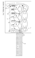
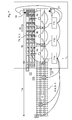
- a container belt 7 runs in a running direction 16, on which empty containers 3 which are partially filled in the further course are introduced.
- the product belt 6 is driven by a drive 18 and the container belt 7 is driven by a drive 19.
- the individual products are counted in a counting area 1a by means of a counting device 8.
- the counting device 8 is connected to controls 11a, 11b, 11c of the infeed robots. In practice, these controls may also be implemented by a single central controller comprising a computer.
- a container feeder 12 for example a Be unitedabstapler
- empty containers are supplied and passed at the inlet of the container belt 7 to this.
- the container feeder 12 is also connected to the individual controllers 11a, 11b, 11c (or a single controller).
- the container feed 12 instead of the container feed 12 at this position a transversely over the container belt 7 extending stopper may be provided, which in turn is to be connected to the controller 11 or the individual controllers 11a, 11b, 11c.
- next empty, possibly pent-up, container 3 is always released as soon as under the counter 8 such a number of individual products 2 have passed through on the product belt 6, as it corresponds to the filling number of a container 3.
- the distance between the individual containers which contain a larger number of fillings, must be greater so that the speed of the container strip is increased to such an extent can be moved, that the product band and the container band at about the same speed.
- Such an increase in the distance is usually not desirable. If, for example, feature-specific, for example, unbalanced, individual products 2 are to be formed as determined by characteristics, for example equilibrium, containers 3, then the greatest possible frequency distribution of the features, in this example the individual weights, of the individual products 2 are to be used there and accordingly the containers 3 should not be too fast be guided through the transfer area 1b.
- FIG. 2 a plan view of an inventive robot road 1 shown.
- the individual products 2 randomly arranged on a product band 6 run in the running direction 17, ie from left to right, under the inlay robots 4a, 4b, 4c,....
- the containers are brought in at a uniform distance by means of a conveyor belt or by means of a transport chain or thermoforming machine.
- the distance of the containers is different from FIG. 1 so far reduced that twice as many containers are arranged on the container belt 7.
- a counter 8 which is arranged in front of the transfer area 1b.
- the container belt 7 moves at half speed relative to the speed of the product belt 6. Accordingly, the length of the counting area 1a corresponds approximately to the length of the conversion area 1b.
- the counting device 8 is connected to the controls 11a, 11b, 11c of the infeed robots. In practice, these controls can also be realized here by a single central controller 11, which comprises a computer.
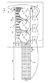
- FIG. 3 is a plan view of a robotic road 1 according to the invention shown, in which the container in uniform, in particular fixed distance by means of a conveyor belt or by means of a transport chain or thermoforming machine are introduced and in which the current frequency of arbitrary on a product tape 6 arranged and brought up individual products 2 deviates from the batch predetermined maximum frequency. Since the containers 3 are introduced at a fixed distance, it is there so that at a Einêtung a container to be filled 3 at the same time a filled container 3 is discharged at the outlet of Umsetz Schl. 1b.
- the target position 1c which reach a counted at the counting position 8 and unreacted individual product 2 and which simultaneously controlled on the container belt 8 container 3 at the same time, based on the outlet of the Umsetz Kunststoffes to the counting position 8 offset.
- This target position 1c is adjusted continuously as a function of the deviation of the current frequency of the transported individual products from the batch-specified maximum frequency and, according to the method, causes an adaptation of the speed of the slowest container band.
- the desired filling level of the containers and the target emptying level of the product strip are also adapted to the current target position 1c.
- the nominal filling levels and the target emptying levels of any further product or container bands are also adapted. If there are several container belts with fixed distances, their speed must also be adjusted.
- FIG. 4 is a further plan view of an inventive robot road 1 shown, in which the container in uneven distance be introduced by means of a conveyor belt or by means of a transport chain in particular by omitting drivers and in which the current frequency of arbitrarily arranged on a product belt 6 and brought up individual products 2 deviates from the batch-predetermined maximum frequency. Since the containers 3 are brought in at a variable distance, it is there so that at a Einêtung a container to be filled 3 is not necessarily at the same time at the outlet of Umsetz Anlagen Schemees 1b a filled container 3 is discharged.
- the target position 1c which at the counting position 8 counted and unreacted individual product 2 and which at the same time on the container belt 8 controlled container 3 reach simultaneously, based on the outlet the Umsetz Schemees Counting position 8 towards as little as possible or not offset.
- the containers 3 can be supplied at a variable distance. This distance is continuously adjusted as a function of the deviation of the current frequency of the transported individual products from the maximum frequency specified in batches.
- the predefined relative speed of the product bands (6; 6a, 6b, 6c) and the container bands (7, 7a, 7b, 7c) and the respective nominal filling stands of the containers 3 and the target discharge stands of the individual products 2 on the product bands (6; 6a, 6b , 6c) are retained as possible.
- the individual products 2 it is also possible, in particular, for the individual products 2 to be controlled in a combined manner in a very irregular manner, the distance between the containers 3 and the displacement of the target position 1c relative to the counting position.
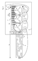
- FIG. 5 is a further view of an inventive Robot Street 1 shown.
- the individual products 2 randomly arranged on a product band 6 run in the running direction 17, ie from left to right, under the inlay robots 4a, 4b, 4c,....
- a pre-accession with maximum frequency is shown.
- the containers are brought in at a uniform distance by means of a conveyor belt or by means of a transport chain or thermoforming machine. The distance of the containers is opposite FIG. 2 stayed the same. Also, the frequency of the individual products supplied remained the same.
- the containers are much smaller than in FIG. 1 and 2 shown.
- a counting device 8 is shown, which is arranged in the transfer region itself. The control of the robot road 1 takes place here with a single controller 11.
- FIG. 5 Parallel to the product belt 6 runs a container belt 7, on which empty containers 3, which are partially filled in the further course, are introduced.
- the containers take 3 in FIG. 5 four times less filling positions than the containers 3 in FIG. 2 .
- the speed of the container belt 7 can be increased so far that all positions of the container 3 by the inlay robots 4a, 4b, 4c, ... can be occupied, it is necessary that the count of the zoomed individual products 2 in Umsetz Scheme 1b itself takes place so that always an empty container 3 is controlled as soon as under the counter 8 such a number of individual products 2 have passed through on the product belt 6, as expected at the position of the counter 8 for the full Filling a container 3 still required number of individual products 2 corresponds to which container 3 reaches the target position based on the outlet from the Umsetz Scheme 1b simultaneously with the position on the product strip 6, at which by means of the counter 8, the individual products 2 are counted.
- the length of the counting region 1a corresponds approximately to half the length of the conversion region 1b.
- the expected at the position of the counter 8 as expected for the complete filling of a container 3 number of individual products 2 can be determined in different ways.
- the individual products 2 already converted into containers 3 can be updated by the controller 11 in the entire conversion area.
- a cascaded filling of the containers 3 proves to be much more advantageous, which makes it possible for the counting of the individual products 2 and the release of a next container 3 to be filled to take place even without a complicated calculation within a counting within the conversion range 1b.
- each individual stacker robot 4a, 4b, 4c, ... in a robot road 1 are designed such that regardless of the frequency of zooming individual products 2 an increase in the filling of the container 3 in the direction of the 16th the container belt 7 is ensured.
- the filling of the container 3 is then realized so that the increase of the filling levels of the container 3 in the transfer area 1b of the robot road 1 by each deposit robot 4a, 4b, 4c, ... is maintained independently and as accurately as possible.
- a desired level is determined for each variety of individual products 2 and for each associated container 3, which in the work area of the respective stacker robot 4a, 4b, 4c, ... to be achieved.
- this loading robot interrupts the further filling of this container 3, although at most further individual products 2 are available in its working area.
- the inlay robots 4a, 4b, 4c, ... are outlined as delta robots in the supervision. However, these can also be other fast insertion robots, such as pickers, SCARA or comparable parallel or serial kinematics.
- These inlay robots 4a, 4b, 4c, ... are each equipped with a gripping device, for example a sucker, which - after activation of a defined position in the horizontal plane by the controller 11 - lowers itself to a single product 2 located there, this then lifts and, after rotation about a vertical axis according to the desired, correct orientation in the container 3 lowers.
- a gripping device for example a sucker
- the grippers of the stacking robots 4a, 4b, 4c, ... know the individual positions on the continuously moving product strip 6 that must be approached, by means of a camera 9a assigned to the stacking robots 4a, 4b, 4c, ... 9b, 9c when passing through the individual products 2 under the respective camera 9a, 9b, 9c every position at which a single product 2 is registered, as well as the rotational position and possibly further features such as weight or color of the individual product 2 determined, and in the control 11 as well as considering the belt speed, which is not always constant in practice.
- each individual product 2 already removed on the product band 6 is also taken into account by the controller 11, so that the respective still existing and to be implemented individual products 2 of the subsequent deposit robot movements of the depositing robot 4a and the subsequent deposit robots 4b, 4c, ... can be implemented.
- the counting device 8 and the cameras 9a, 9b, 9c are combined in a single camera arranged in front of the conversion region 1b, which at the same time serves as counting device 8 and camera 9a, 9b, 9c for position, rotational position and possibly feature determination the individual products 2 is used.
- the position of the count 1a of the individual products 2 can then be pushed to the point which results from the speed of the product belt 6 and the container belt 7 as a function of a charge.
- the camera 9a and possibly the further cameras 9b, 9c, etc. are then used for position, rotational position and, if necessary, for characterizing the individual products 2 or are not required.
- FIG. 6 is a plan view of another robotic road 1 according to the invention shown.
- the product band is made in two parts and each part has a counting device.
- the individual products 2 arranged on a product band 6 run in the running direction 17, ie from left to right, under the stacking robots 4a, 4b, 4c,....
- a counter 22 and a independently driven compensating belt 21 is shown, which are arranged immediately in front of the product belt 6 and the counting device 8 arranged on this product belt.
- Parallel to the product belt 6 runs a container belt 7, on which empty containers 3, which are partially filled in the further course, are introduced.
- the product band 6 is preceded by a compensating belt 21 here.
- This has its own drive 20 and a compensating counter 22 whose detection range covers the inlet area of the compensating belt 21.
- the compensating belt 21 can be brought to a standstill via the drive 20 until again individual products 2 are detected by the compensating counter 22.
- On the compensating belt an exemplary arrangement 24 of individual products 2 is shown. So it may be that temporarily no products are delivered. Then the product belt 6 and the container belt 7 can be brought to a standstill until individual products arrive at the inlet of the product belt 6 again.
- the arrangement 24 of the individual products 2 shows that after the interruption of production only three tracks are occupied by individual products 2.
- the product belt 6 and the container belt 7 can be operated at half speed until all six tracks are again covered with individual products, as also shown in arrangement 24. If, as shown in the further course of the arrangement 24, a complete series of individual product 2 is missing, then the product band 6 and the container band 7 can be stopped briefly to compensate for the missing row.
- the compensating belt 21 can also be realized by means of a transport device required for the last production step of the individual products.
- individual products 2 often go through a cooling tunnel at the end.
- the compensation counter 22 can be arranged at the inlet of the cooling tunnel.
- the speed of the compensating belt 21 can not be adjusted.
- the compensation count and possibly also the determination of the characteristics of the individual products 2 takes place during the actual processing of the poultry and is transmitted as a data stream via a data bus to the controllers 11a, 11b, 11c or a single control. If this balance count or data stream is updated accordingly, taking into account the speed of the cooling belt or the chain guide, then the continuous adjustment of the speed of the product belt 6 and the container belt 7 can be due to this updated single product count.
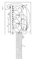
- FIG. 7 is a plan view of another robotic road 1 according to the invention shown. Again, the run on individual products 2 in the direction 17, ie from left to right, under the stacking robots 4a, 4b, 4c, ... by. However, these are arranged on three product bands 6a, 6b, 6c. A counter is shown for each product band.
- the slowest container band 7a shows a variable container distance.
- the further container belts (7b, 7c) show a fixed container distance. It is also possible that only bands are used with a fixed distance, in which case the target position 1c shifts also here to the counting position.
- the three product belts 6a, 6b, 6c run at different speeds.
- the fastest product band 6a is twice as fast as the slowest moving container band 7a.
- the slowest product belt 6c is only moved about 25% faster. This also results in the different counting positions 8a, 8b, 8c.
Landscapes
- Engineering & Computer Science (AREA)
- Mechanical Engineering (AREA)
- Auxiliary Devices For And Details Of Packaging Control (AREA)
- Container Filling Or Packaging Operations (AREA)
- Control Of Conveyors (AREA)
- Containers And Plastic Fillers For Packaging (AREA)
Priority Applications (2)
| Application Number | Priority Date | Filing Date | Title |
|---|---|---|---|
| EP12191048.3A EP2664553B1 (fr) | 2012-05-03 | 2012-11-02 | Procédé d'insertion de produits individuels dans des récipients dans une suite de robots |
| US14/070,449 US20140123606A1 (en) | 2012-05-03 | 2013-11-01 | Method and Device To Insert Individual Products Into Containers In An Automated Line |
Applications Claiming Priority (2)
| Application Number | Priority Date | Filing Date | Title |
|---|---|---|---|
| EP12166610 | 2012-05-03 | ||
| EP12191048.3A EP2664553B1 (fr) | 2012-05-03 | 2012-11-02 | Procédé d'insertion de produits individuels dans des récipients dans une suite de robots |
Publications (3)
| Publication Number | Publication Date |
|---|---|
| EP2664553A2 true EP2664553A2 (fr) | 2013-11-20 |
| EP2664553A3 EP2664553A3 (fr) | 2016-10-05 |
| EP2664553B1 EP2664553B1 (fr) | 2017-09-20 |
Family
ID=47076128
Family Applications (1)
| Application Number | Title | Priority Date | Filing Date |
|---|---|---|---|
| EP12191048.3A Not-in-force EP2664553B1 (fr) | 2012-05-03 | 2012-11-02 | Procédé d'insertion de produits individuels dans des récipients dans une suite de robots |
Country Status (2)
| Country | Link |
|---|---|
| US (1) | US20140123606A1 (fr) |
| EP (1) | EP2664553B1 (fr) |
Cited By (3)
| Publication number | Priority date | Publication date | Assignee | Title |
|---|---|---|---|---|
| DE102019113287A1 (de) * | 2019-05-20 | 2020-11-26 | Gerhard Schubert Gmbh | Verfahren zum Umsetzen von Produkten sowie hierfür geeigneter Umsetz-Roboter |
| EP3909872A1 (fr) * | 2020-05-12 | 2021-11-17 | Uhlmann Pac-Systeme GmbH & Co. KG | Procédé et agencement de transport de produits |
| EP3483077B1 (fr) | 2017-11-10 | 2023-11-01 | Weber Maschinenbau GmbH Breidenbach | Procédé de positionnement des denrées alimentaires |
Families Citing this family (12)
| Publication number | Priority date | Publication date | Assignee | Title |
|---|---|---|---|---|
| EP2586712B2 (fr) | 2011-10-31 | 2018-02-14 | Veltru AG | Procédé et dispositif d'insertion de produits dans des récipients dans une suite de robots |
| ITBO20130162A1 (it) * | 2013-04-12 | 2014-10-13 | Marchesini Group Spa | Metodo e sistema per sincronizzare una stazione di lavorazione di una macchina blisteratrice con l'avanzamento di un nastro blister |
| US12198091B2 (en) * | 2013-06-17 | 2025-01-14 | Symbol Technologies, Llc | Real-time trailer utilization measurement |
| US10040194B1 (en) * | 2015-01-29 | 2018-08-07 | Vecna Technologies, Inc. | Order picking method and mechanism |
| JP2016175708A (ja) * | 2015-03-18 | 2016-10-06 | 株式会社イシダ | 物品集積装置 |
| US9940730B2 (en) | 2015-11-18 | 2018-04-10 | Symbol Technologies, Llc | Methods and systems for automatic fullness estimation of containers |
| US10713610B2 (en) | 2015-12-22 | 2020-07-14 | Symbol Technologies, Llc | Methods and systems for occlusion detection and data correction for container-fullness estimation |
| CN109789545B (zh) | 2016-10-12 | 2022-03-18 | Abb瑞士股份有限公司 | 用于控制输送路径的速度的方法和系统 |
| CN111867936B (zh) * | 2018-03-16 | 2022-03-18 | 利乐拉瓦尔集团及财务有限公司 | 使用哈希树跟踪食品安全数据的食品包装机 |
| US10783656B2 (en) | 2018-05-18 | 2020-09-22 | Zebra Technologies Corporation | System and method of determining a location for placement of a package |
| US11136149B2 (en) * | 2018-08-03 | 2021-10-05 | Futurewei Technologies, Inc. | Container packing system |
| DK180355B1 (en) * | 2019-09-06 | 2021-02-01 | Marel Iceland Ehf | A method and a system for filling containers with food items |
Citations (13)
| Publication number | Priority date | Publication date | Assignee | Title |
|---|---|---|---|---|
| DE2506446A1 (de) | 1975-02-15 | 1976-08-26 | Hassia Verpackung Gmbh | Tiefziehmaschine |
| DE4208818C2 (de) | 1992-03-19 | 1994-09-08 | Haensel Otto Gmbh | Verfahren und Vorrichtung zum Einlegen von Artikeln in Verpackungseinsätze |
| EP0749902A1 (fr) | 1995-06-20 | 1996-12-27 | Gerhard Schubert GmbH | Procédé pour déposer un nombre déterminé de produits dans un récipient |
| DE29701564U1 (de) | 1997-01-30 | 1997-03-27 | Gerhard Schubert GmbH, 74564 Crailsheim | Pickerstraße mit entgegengesetztem Traytransport |
| EP0856465A1 (fr) | 1997-01-30 | 1998-08-05 | Gerhard Schubert GmbH | Transport de plateaux à directions opposées pour table de préhension |
| EP1285851A1 (fr) | 2001-08-22 | 2003-02-26 | SIG Pack Systems AG | Procédé et appareil pour remplir des conteneurs avec des marchandises |
| EP1352831A1 (fr) | 2002-04-02 | 2003-10-15 | SIG Pack Systems AG | Procédé et appareil pour déposer des marchandises dans des conteneurs |
| US6722506B1 (en) | 1998-10-15 | 2004-04-20 | Scanvaegt International A/S | Method for weight controlled batching out of articles having non-uniform weight |
| WO2005106405A1 (fr) | 2004-05-04 | 2005-11-10 | Sverre Stenbom | Methode et dispositif de tri et d'emballage de produits |
| EP1819994A1 (fr) | 2004-12-10 | 2007-08-22 | Scanvaegt International A/S | Procede et systeme d'etablissement de lots d'objets |
| WO2008080760A1 (fr) | 2006-12-27 | 2008-07-10 | Robert Bosch Gmbh | Procédé et dispositif pour déplacer des marchandises au détail |
| EP2233400A1 (fr) | 2009-03-25 | 2010-09-29 | OPM S.p.A. | Procédé et dispositif d'emballage |
| EP2236424A1 (fr) | 2009-03-30 | 2010-10-06 | Veltru AG | Procédé et dispositif d'insertion de produits individuels dans des récipients dans une suite de robots |
Family Cites Families (1)
| Publication number | Priority date | Publication date | Assignee | Title |
|---|---|---|---|---|
| CH693710A5 (de) * | 1999-07-02 | 2003-12-31 | Sig Pack Systems Ag | Verfahren zum Picken und Plazieren von Stückgütern. |
-
2012
- 2012-11-02 EP EP12191048.3A patent/EP2664553B1/fr not_active Not-in-force
-
2013
- 2013-11-01 US US14/070,449 patent/US20140123606A1/en not_active Abandoned
Patent Citations (14)
| Publication number | Priority date | Publication date | Assignee | Title |
|---|---|---|---|---|
| DE2506446A1 (de) | 1975-02-15 | 1976-08-26 | Hassia Verpackung Gmbh | Tiefziehmaschine |
| DE4208818C2 (de) | 1992-03-19 | 1994-09-08 | Haensel Otto Gmbh | Verfahren und Vorrichtung zum Einlegen von Artikeln in Verpackungseinsätze |
| EP0749902A1 (fr) | 1995-06-20 | 1996-12-27 | Gerhard Schubert GmbH | Procédé pour déposer un nombre déterminé de produits dans un récipient |
| DE29701564U1 (de) | 1997-01-30 | 1997-03-27 | Gerhard Schubert GmbH, 74564 Crailsheim | Pickerstraße mit entgegengesetztem Traytransport |
| EP0856465A1 (fr) | 1997-01-30 | 1998-08-05 | Gerhard Schubert GmbH | Transport de plateaux à directions opposées pour table de préhension |
| US6722506B1 (en) | 1998-10-15 | 2004-04-20 | Scanvaegt International A/S | Method for weight controlled batching out of articles having non-uniform weight |
| EP1285851A1 (fr) | 2001-08-22 | 2003-02-26 | SIG Pack Systems AG | Procédé et appareil pour remplir des conteneurs avec des marchandises |
| EP1352831A1 (fr) | 2002-04-02 | 2003-10-15 | SIG Pack Systems AG | Procédé et appareil pour déposer des marchandises dans des conteneurs |
| WO2005106405A1 (fr) | 2004-05-04 | 2005-11-10 | Sverre Stenbom | Methode et dispositif de tri et d'emballage de produits |
| EP1819994A1 (fr) | 2004-12-10 | 2007-08-22 | Scanvaegt International A/S | Procede et systeme d'etablissement de lots d'objets |
| US7775373B2 (en) | 2004-12-10 | 2010-08-17 | Scanvaegt International A/S | Method and a system for batching of objects |
| WO2008080760A1 (fr) | 2006-12-27 | 2008-07-10 | Robert Bosch Gmbh | Procédé et dispositif pour déplacer des marchandises au détail |
| EP2233400A1 (fr) | 2009-03-25 | 2010-09-29 | OPM S.p.A. | Procédé et dispositif d'emballage |
| EP2236424A1 (fr) | 2009-03-30 | 2010-10-06 | Veltru AG | Procédé et dispositif d'insertion de produits individuels dans des récipients dans une suite de robots |
Cited By (6)
| Publication number | Priority date | Publication date | Assignee | Title |
|---|---|---|---|---|
| EP3483077B1 (fr) | 2017-11-10 | 2023-11-01 | Weber Maschinenbau GmbH Breidenbach | Procédé de positionnement des denrées alimentaires |
| DE102019113287A1 (de) * | 2019-05-20 | 2020-11-26 | Gerhard Schubert Gmbh | Verfahren zum Umsetzen von Produkten sowie hierfür geeigneter Umsetz-Roboter |
| EP3909872A1 (fr) * | 2020-05-12 | 2021-11-17 | Uhlmann Pac-Systeme GmbH & Co. KG | Procédé et agencement de transport de produits |
| CN113716111A (zh) * | 2020-05-12 | 2021-11-30 | 乌尔曼包装系统有限责任及合伙两合公司 | 用于转移产品的方法和组件 |
| US11542107B2 (en) | 2020-05-12 | 2023-01-03 | Uhlmann Pac-Systeme Gmbh & Co. Kg | Method and assembly for transferring products |
| EP4530206A3 (fr) * | 2020-05-12 | 2025-06-04 | Uhlmann Pac-Systeme GmbH & Co. KG | Procédé et dispositif de transfert de produits |
Also Published As
| Publication number | Publication date |
|---|---|
| EP2664553A3 (fr) | 2016-10-05 |
| US20140123606A1 (en) | 2014-05-08 |
| EP2664553B1 (fr) | 2017-09-20 |
Similar Documents
| Publication | Publication Date | Title |
|---|---|---|
| EP2664553B1 (fr) | Procédé d'insertion de produits individuels dans des récipients dans une suite de robots | |
| EP2616341B1 (fr) | Procédé et dispositif pour remplir de produits individuels une barquette d'emballage à plusieurs rangées | |
| EP2669202B1 (fr) | Procédé pour table de préhension et installation d'emballage | |
| DE69008458T2 (de) | Verfahren und Apparat für die Puffersteuerung in Fördersystemen. | |
| EP2236424B1 (fr) | Procédé et dispositif d'insertion de produits individuels dans des récipients dans une suite de robots | |
| DE60208983T2 (de) | Fördereinrichtung zum Transferieren von Stapeln von auf einer Kante stehenden Gegenständen | |
| DE102007040367B4 (de) | Materialflusssteuerung zur Kollisionsvermeidung in einer Förderanlage | |
| EP2586712B1 (fr) | Procédé et dispositif d'insertion de produits dans des récipients dans une suite de robots | |
| EP1173361B1 (fr) | Installation et procede pour remplir des contenants avec des produits | |
| EP3453654A1 (fr) | Procédé et dispositif de positionnement, et d'alignement, et d'emballage groupés des denrées alimentaires individuelles | |
| EP2799348B1 (fr) | Procédé de regroupement d'articles en un faisceau d'articles et dispositif de regroupement et machine d'emballage doté d'un tel dispositif | |
| EP3153025B1 (fr) | Dispositif destine au traitement individuel de saucisse | |
| DE102007021146A1 (de) | Vorrichtung und Verfahren zum Handhaben von flachen Gegenständen, insbesondere Windeln | |
| EP3414194B1 (fr) | Procédé et dispositif de regroupement d'ébauches de produits | |
| EP2520497B1 (fr) | Procédé d'insertion de produits individuels dans des récipients dans une suite de robots | |
| EP3303153B1 (fr) | Procédé et dispositif permettant d'introduire des produits dans des contenants | |
| EP2040984B1 (fr) | Procede de remplissage de conteneurs avec des marchandises diverses | |
| DE69214122T2 (de) | Verfahren und system zum aufreihen von artikeln | |
| EP1732810B1 (fr) | Procede de manipulation d'un blister dans une machine d'emballage blister, et dispositif pour la mise en oeuvre de ce procede | |
| EP2882653B1 (fr) | Installation de fabrication et d'emballage pour produits d'hygiène et un procédé pour son opération | |
| EP3652093A1 (fr) | Procédé et dispositif pour manipuler des marchandises, articles et/ou paquets | |
| EP3770086B1 (fr) | Procédé et dispositif de manipulation des marchandises déplacées les unes après les autres dans au moins une rangée | |
| EP2133293B1 (fr) | Dispositif de transmission de marchandises sur un système de transport de marchandises ou sur un dispositif de stockage | |
| EP3483077A1 (fr) | Procédé de positionnement des denrées alimentaires | |
| DE19930368A1 (de) | Verfahren und Vorrichtung zum Verpacken von flachen Produkten |
Legal Events
| Date | Code | Title | Description |
|---|---|---|---|
| PUAI | Public reference made under article 153(3) epc to a published international application that has entered the european phase |
Free format text: ORIGINAL CODE: 0009012 |
|
| AK | Designated contracting states |
Kind code of ref document: A2 Designated state(s): AL AT BE BG CH CY CZ DE DK EE ES FI FR GB GR HR HU IE IS IT LI LT LU LV MC MK MT NL NO PL PT RO RS SE SI SK SM TR |
|
| AX | Request for extension of the european patent |
Extension state: BA ME |
|
| PUAL | Search report despatched |
Free format text: ORIGINAL CODE: 0009013 |
|
| AK | Designated contracting states |
Kind code of ref document: A3 Designated state(s): AL AT BE BG CH CY CZ DE DK EE ES FI FR GB GR HR HU IE IS IT LI LT LU LV MC MK MT NL NO PL PT RO RS SE SI SK SM TR |
|
| AX | Request for extension of the european patent |
Extension state: BA ME |
|
| RIC1 | Information provided on ipc code assigned before grant |
Ipc: B65B 5/12 20060101ALI20160829BHEP Ipc: B65B 5/10 20060101AFI20160829BHEP |
|
| 17P | Request for examination filed |
Effective date: 20170330 |
|
| RBV | Designated contracting states (corrected) |
Designated state(s): AL AT BE BG CH CY CZ DE DK EE ES FI FR GB GR HR HU IE IS IT LI LT LU LV MC MK MT NL NO PL PT RO RS SE SI SK SM TR |
|
| GRAP | Despatch of communication of intention to grant a patent |
Free format text: ORIGINAL CODE: EPIDOSNIGR1 |
|
| INTG | Intention to grant announced |
Effective date: 20170517 |
|
| GRAS | Grant fee paid |
Free format text: ORIGINAL CODE: EPIDOSNIGR3 |
|
| GRAA | (expected) grant |
Free format text: ORIGINAL CODE: 0009210 |
|
| AK | Designated contracting states |
Kind code of ref document: B1 Designated state(s): AL AT BE BG CH CY CZ DE DK EE ES FI FR GB GR HR HU IE IS IT LI LT LU LV MC MK MT NL NO PL PT RO RS SE SI SK SM TR |
|
| REG | Reference to a national code |
Ref country code: GB Ref legal event code: FG4D Free format text: NOT ENGLISH |
|
| REG | Reference to a national code |
Ref country code: CH Ref legal event code: EP |
|
| REG | Reference to a national code |
Ref country code: AT Ref legal event code: REF Ref document number: 929921 Country of ref document: AT Kind code of ref document: T Effective date: 20171015 |
|
| REG | Reference to a national code |
Ref country code: IE Ref legal event code: FG4D Free format text: LANGUAGE OF EP DOCUMENT: GERMAN |
|
| REG | Reference to a national code |
Ref country code: DE Ref legal event code: R096 Ref document number: 502012011302 Country of ref document: DE |
|
| REG | Reference to a national code |
Ref country code: NL Ref legal event code: MP Effective date: 20170920 |
|
| PG25 | Lapsed in a contracting state [announced via postgrant information from national office to epo] |
Ref country code: LT Free format text: LAPSE BECAUSE OF FAILURE TO SUBMIT A TRANSLATION OF THE DESCRIPTION OR TO PAY THE FEE WITHIN THE PRESCRIBED TIME-LIMIT Effective date: 20170920 Ref country code: FI Free format text: LAPSE BECAUSE OF FAILURE TO SUBMIT A TRANSLATION OF THE DESCRIPTION OR TO PAY THE FEE WITHIN THE PRESCRIBED TIME-LIMIT Effective date: 20170920 Ref country code: NO Free format text: LAPSE BECAUSE OF FAILURE TO SUBMIT A TRANSLATION OF THE DESCRIPTION OR TO PAY THE FEE WITHIN THE PRESCRIBED TIME-LIMIT Effective date: 20171220 Ref country code: SE Free format text: LAPSE BECAUSE OF FAILURE TO SUBMIT A TRANSLATION OF THE DESCRIPTION OR TO PAY THE FEE WITHIN THE PRESCRIBED TIME-LIMIT Effective date: 20170920 Ref country code: HR Free format text: LAPSE BECAUSE OF FAILURE TO SUBMIT A TRANSLATION OF THE DESCRIPTION OR TO PAY THE FEE WITHIN THE PRESCRIBED TIME-LIMIT Effective date: 20170920 |
|
| REG | Reference to a national code |
Ref country code: LT Ref legal event code: MG4D |
|
| PG25 | Lapsed in a contracting state [announced via postgrant information from national office to epo] |
Ref country code: RS Free format text: LAPSE BECAUSE OF FAILURE TO SUBMIT A TRANSLATION OF THE DESCRIPTION OR TO PAY THE FEE WITHIN THE PRESCRIBED TIME-LIMIT Effective date: 20170920 Ref country code: GR Free format text: LAPSE BECAUSE OF FAILURE TO SUBMIT A TRANSLATION OF THE DESCRIPTION OR TO PAY THE FEE WITHIN THE PRESCRIBED TIME-LIMIT Effective date: 20171221 Ref country code: LV Free format text: LAPSE BECAUSE OF FAILURE TO SUBMIT A TRANSLATION OF THE DESCRIPTION OR TO PAY THE FEE WITHIN THE PRESCRIBED TIME-LIMIT Effective date: 20170920 Ref country code: BG Free format text: LAPSE BECAUSE OF FAILURE TO SUBMIT A TRANSLATION OF THE DESCRIPTION OR TO PAY THE FEE WITHIN THE PRESCRIBED TIME-LIMIT Effective date: 20171220 |
|
| PG25 | Lapsed in a contracting state [announced via postgrant information from national office to epo] |
Ref country code: NL Free format text: LAPSE BECAUSE OF FAILURE TO SUBMIT A TRANSLATION OF THE DESCRIPTION OR TO PAY THE FEE WITHIN THE PRESCRIBED TIME-LIMIT Effective date: 20170920 |
|
| PG25 | Lapsed in a contracting state [announced via postgrant information from national office to epo] |
Ref country code: ES Free format text: LAPSE BECAUSE OF FAILURE TO SUBMIT A TRANSLATION OF THE DESCRIPTION OR TO PAY THE FEE WITHIN THE PRESCRIBED TIME-LIMIT Effective date: 20170920 Ref country code: PL Free format text: LAPSE BECAUSE OF FAILURE TO SUBMIT A TRANSLATION OF THE DESCRIPTION OR TO PAY THE FEE WITHIN THE PRESCRIBED TIME-LIMIT Effective date: 20170920 Ref country code: CZ Free format text: LAPSE BECAUSE OF FAILURE TO SUBMIT A TRANSLATION OF THE DESCRIPTION OR TO PAY THE FEE WITHIN THE PRESCRIBED TIME-LIMIT Effective date: 20170920 Ref country code: RO Free format text: LAPSE BECAUSE OF FAILURE TO SUBMIT A TRANSLATION OF THE DESCRIPTION OR TO PAY THE FEE WITHIN THE PRESCRIBED TIME-LIMIT Effective date: 20170920 |
|
| PG25 | Lapsed in a contracting state [announced via postgrant information from national office to epo] |
Ref country code: EE Free format text: LAPSE BECAUSE OF FAILURE TO SUBMIT A TRANSLATION OF THE DESCRIPTION OR TO PAY THE FEE WITHIN THE PRESCRIBED TIME-LIMIT Effective date: 20170920 Ref country code: IS Free format text: LAPSE BECAUSE OF FAILURE TO SUBMIT A TRANSLATION OF THE DESCRIPTION OR TO PAY THE FEE WITHIN THE PRESCRIBED TIME-LIMIT Effective date: 20180120 Ref country code: IT Free format text: LAPSE BECAUSE OF FAILURE TO SUBMIT A TRANSLATION OF THE DESCRIPTION OR TO PAY THE FEE WITHIN THE PRESCRIBED TIME-LIMIT Effective date: 20170920 Ref country code: SK Free format text: LAPSE BECAUSE OF FAILURE TO SUBMIT A TRANSLATION OF THE DESCRIPTION OR TO PAY THE FEE WITHIN THE PRESCRIBED TIME-LIMIT Effective date: 20170920 Ref country code: SM Free format text: LAPSE BECAUSE OF FAILURE TO SUBMIT A TRANSLATION OF THE DESCRIPTION OR TO PAY THE FEE WITHIN THE PRESCRIBED TIME-LIMIT Effective date: 20170920 |
|
| REG | Reference to a national code |
Ref country code: DE Ref legal event code: R097 Ref document number: 502012011302 Country of ref document: DE |
|
| PG25 | Lapsed in a contracting state [announced via postgrant information from national office to epo] |
Ref country code: MC Free format text: LAPSE BECAUSE OF FAILURE TO SUBMIT A TRANSLATION OF THE DESCRIPTION OR TO PAY THE FEE WITHIN THE PRESCRIBED TIME-LIMIT Effective date: 20170920 |
|
| PLBE | No opposition filed within time limit |
Free format text: ORIGINAL CODE: 0009261 |
|
| STAA | Information on the status of an ep patent application or granted ep patent |
Free format text: STATUS: NO OPPOSITION FILED WITHIN TIME LIMIT |
|
| PG25 | Lapsed in a contracting state [announced via postgrant information from national office to epo] |
Ref country code: CH Free format text: LAPSE BECAUSE OF NON-PAYMENT OF DUE FEES Effective date: 20171130 Ref country code: LI Free format text: LAPSE BECAUSE OF NON-PAYMENT OF DUE FEES Effective date: 20171130 Ref country code: DK Free format text: LAPSE BECAUSE OF FAILURE TO SUBMIT A TRANSLATION OF THE DESCRIPTION OR TO PAY THE FEE WITHIN THE PRESCRIBED TIME-LIMIT Effective date: 20170920 |
|
| PGFP | Annual fee paid to national office [announced via postgrant information from national office to epo] |
Ref country code: DE Payment date: 20180525 Year of fee payment: 6 |
|
| 26N | No opposition filed |
Effective date: 20180621 |
|
| GBPC | Gb: european patent ceased through non-payment of renewal fee |
Effective date: 20171220 |
|
| PG25 | Lapsed in a contracting state [announced via postgrant information from national office to epo] |
Ref country code: LU Free format text: LAPSE BECAUSE OF NON-PAYMENT OF DUE FEES Effective date: 20171102 |
|
| REG | Reference to a national code |
Ref country code: FR Ref legal event code: ST Effective date: 20180731 Ref country code: BE Ref legal event code: MM Effective date: 20171130 |
|
| REG | Reference to a national code |
Ref country code: IE Ref legal event code: MM4A |
|
| PG25 | Lapsed in a contracting state [announced via postgrant information from national office to epo] |
Ref country code: MT Free format text: LAPSE BECAUSE OF FAILURE TO SUBMIT A TRANSLATION OF THE DESCRIPTION OR TO PAY THE FEE WITHIN THE PRESCRIBED TIME-LIMIT Effective date: 20170920 |
|
| PG25 | Lapsed in a contracting state [announced via postgrant information from national office to epo] |
Ref country code: IE Free format text: LAPSE BECAUSE OF NON-PAYMENT OF DUE FEES Effective date: 20171102 Ref country code: FR Free format text: LAPSE BECAUSE OF NON-PAYMENT OF DUE FEES Effective date: 20171130 |
|
| PG25 | Lapsed in a contracting state [announced via postgrant information from national office to epo] |
Ref country code: GB Free format text: LAPSE BECAUSE OF NON-PAYMENT OF DUE FEES Effective date: 20171220 Ref country code: BE Free format text: LAPSE BECAUSE OF NON-PAYMENT OF DUE FEES Effective date: 20171130 Ref country code: SI Free format text: LAPSE BECAUSE OF FAILURE TO SUBMIT A TRANSLATION OF THE DESCRIPTION OR TO PAY THE FEE WITHIN THE PRESCRIBED TIME-LIMIT Effective date: 20170920 |
|
| REG | Reference to a national code |
Ref country code: AT Ref legal event code: MM01 Ref document number: 929921 Country of ref document: AT Kind code of ref document: T Effective date: 20171102 |
|
| PG25 | Lapsed in a contracting state [announced via postgrant information from national office to epo] |
Ref country code: AT Free format text: LAPSE BECAUSE OF NON-PAYMENT OF DUE FEES Effective date: 20171102 |
|
| REG | Reference to a national code |
Ref country code: DE Ref legal event code: R119 Ref document number: 502012011302 Country of ref document: DE |
|
| PG25 | Lapsed in a contracting state [announced via postgrant information from national office to epo] |
Ref country code: HU Free format text: LAPSE BECAUSE OF FAILURE TO SUBMIT A TRANSLATION OF THE DESCRIPTION OR TO PAY THE FEE WITHIN THE PRESCRIBED TIME-LIMIT; INVALID AB INITIO Effective date: 20121102 |
|
| PG25 | Lapsed in a contracting state [announced via postgrant information from national office to epo] |
Ref country code: DE Free format text: LAPSE BECAUSE OF NON-PAYMENT OF DUE FEES Effective date: 20190601 Ref country code: CY Free format text: LAPSE BECAUSE OF NON-PAYMENT OF DUE FEES Effective date: 20170920 |
|
| PG25 | Lapsed in a contracting state [announced via postgrant information from national office to epo] |
Ref country code: MK Free format text: LAPSE BECAUSE OF FAILURE TO SUBMIT A TRANSLATION OF THE DESCRIPTION OR TO PAY THE FEE WITHIN THE PRESCRIBED TIME-LIMIT Effective date: 20170920 |
|
| PG25 | Lapsed in a contracting state [announced via postgrant information from national office to epo] |
Ref country code: TR Free format text: LAPSE BECAUSE OF FAILURE TO SUBMIT A TRANSLATION OF THE DESCRIPTION OR TO PAY THE FEE WITHIN THE PRESCRIBED TIME-LIMIT Effective date: 20170920 |
|
| PG25 | Lapsed in a contracting state [announced via postgrant information from national office to epo] |
Ref country code: PT Free format text: LAPSE BECAUSE OF FAILURE TO SUBMIT A TRANSLATION OF THE DESCRIPTION OR TO PAY THE FEE WITHIN THE PRESCRIBED TIME-LIMIT Effective date: 20170920 |
|
| PG25 | Lapsed in a contracting state [announced via postgrant information from national office to epo] |
Ref country code: AL Free format text: LAPSE BECAUSE OF FAILURE TO SUBMIT A TRANSLATION OF THE DESCRIPTION OR TO PAY THE FEE WITHIN THE PRESCRIBED TIME-LIMIT Effective date: 20170920 |