EP2664751A1 - Distribution pour un moteur à combustion interne commandé par soupape - Google Patents
Distribution pour un moteur à combustion interne commandé par soupape Download PDFInfo
- Publication number
- EP2664751A1 EP2664751A1 EP13001882.3A EP13001882A EP2664751A1 EP 2664751 A1 EP2664751 A1 EP 2664751A1 EP 13001882 A EP13001882 A EP 13001882A EP 2664751 A1 EP2664751 A1 EP 2664751A1
- Authority
- EP
- European Patent Office
- Prior art keywords
- gear
- internal combustion
- combustion engine
- camshaft
- drive according
- Prior art date
- Legal status (The legal status is an assumption and is not a legal conclusion. Google has not performed a legal analysis and makes no representation as to the accuracy of the status listed.)
- Granted
Links
Images


Classifications
-
- F—MECHANICAL ENGINEERING; LIGHTING; HEATING; WEAPONS; BLASTING
- F01—MACHINES OR ENGINES IN GENERAL; ENGINE PLANTS IN GENERAL; STEAM ENGINES
- F01L—CYCLICALLY OPERATING VALVES FOR MACHINES OR ENGINES
- F01L1/00—Valve-gear or valve arrangements, e.g. lift-valve gear
- F01L1/02—Valve drive
- F01L1/026—Gear drive
-
- F—MECHANICAL ENGINEERING; LIGHTING; HEATING; WEAPONS; BLASTING
- F16—ENGINEERING ELEMENTS AND UNITS; GENERAL MEASURES FOR PRODUCING AND MAINTAINING EFFECTIVE FUNCTIONING OF MACHINES OR INSTALLATIONS; THERMAL INSULATION IN GENERAL
- F16H—GEARING
- F16H57/00—General details of gearing
- F16H57/02—Gearboxes; Mounting gearing therein
- F16H57/021—Shaft support structures, e.g. partition walls, bearing eyes, casing walls or covers with bearings
- F16H57/022—Adjustment of gear shafts or bearings
- F16H2057/0222—Lateral adjustment
Definitions
- the present invention relates to a timing drive for a valve-controlled internal combustion engine according to the preamble of patent claim 1.
- the object of the invention is to propose a timing drive of the generic type, which in a robust construction with simple means an exact Compensation of possible occurring during repair conditions center distances and possibly a readjustment of the valve timing.
- the bearing pin for the intermediate gear can be fastened in at least two positions on the end face of the internal combustion engine. These positions preferably correspond to a new state of the internal combustion engine and a defined repair state of the internal combustion engine with changed center distances between the crankshaft and the camshaft.
- the basic idea of the invention is, in the case of an overhaul of the engine and a required scheduling of the cylinder crankcase and / or the cylinder head, to specify a defined execution (for example 0.5 mm) as the first step and to calculate a constructively calculated, on the timing drive for the bearing journal, provide second mounting position, which in turn results in optimum meshing conditions for the changed center distance of the spur gears.
- the robust construction of the timing gear with an always fixed bearing pin for the intermediate gear is given in both positions.
- the bearing journal can be fastened by means of a plurality of fastening elements, in particular fastening screws, on the end face of the internal combustion engine, wherein for each of the positions separate counter-elements, for example tapped holes, are incorporated in the end face.
- the bearing pin for the intermediate gear is then converted via the corresponding threaded holes and mounting screws in a simple manner or firmly positioned.
- two open to the front side Schmieröllanäle may be provided on the front side of the engine, which are aligned in one or the other position with a lubricating oil passage in the journal of the intermediate gear.
- the bearing pin can close one of the lubricating oil channels in one or the other position. If necessary, can but also the one or the other lubricating oil channel are closed by means of a grub screw.
- a convertible centering be used, which forms an exact positioning of the journal in the respective position with a corresponding recess in the bearing journal.
- spur gear An optionally adjusted by the changed center distances valve timing change can be compensated by the spur gear is designed to be adjustable on the camshaft in the circumferential direction relative to the camshaft.
- the spur gear may be replaceable on the camshaft in the repair state of the internal combustion engine by a manufactured for the repair condition spur gear with a valve timing change corresponding, phase-shifted teeth.
- Einstelltechnikrad intermediate gear which is mounted on a further stationary bearing pin on the front side of the internal combustion engine and by means of an exact timing adjustment of the valves of the internal combustion engine is feasible.
- the Einstell leopardrad may in particular be formed by two mutually circumferentially adjustable gears, of which one gear meshes with one of the spur gears and the other gear with the interposable into two positions intermediate gear.
- this proposal assumes that a two-track timing drive is used, with a corresponding, axial displacement of the meshing with the Einstelltechnikrad gears.
- the two gears of the Einstelltechnikrads be loosened to each other, then the crankshaft and the camshaft adjusted in a defined OT position, for example, the piston of the first cylinder of the internal combustion engine and then attached the gears of the Einstelltechnikrads in this position together.
- Einstell leopardrad can also be used between the two gears engaging in a circumferential groove of the journal, held between the gears lock washer, whereby Einstelltechnikrad and bearing pin can form a pre-assembly and / or can account for an axially leading bearing collar on the journal.
- the spur gear on the crankshaft meshes with the larger gear of a step gear whose smaller, offset-offset gear is engaged with the intermediate gear and further that the intermediate gear with the one gear of the Einstelltechnikrads and the second gear of the adjusting gear meshes with the spur gear on the camshaft.
- the spur gears on the crankshaft and the camshaft and the larger gear of the step gear and the one gear of the Einstelltechnikrads in a single gear plane and the smaller gear on the step gear and the second gear of the Einstelltechnikrads on a second, underlying gear level preferably the spur gears on the crankshaft and the camshaft and the larger gear of the step gear and the one gear of the Einstelltechnikrads in a single gear plane and the smaller gear on the step gear and the second gear of the Einstelltechnikrads on a second, underlying gear level.
- interposable intermediate gear and optionally the step gear in two positions can be arranged on the end face of the crankcase of the internal combustion engine and the Einstelltechnikrad on the corresponding end face of the cylinder head.
- the Fig. 1 and 2 show a timing drive 1 for a valve-controlled four-stroke internal combustion engine with an overhead, rotatably mounted in a cylinder head 2 and acting in a known manner gas exchange valves camshaft 3 with a driven spur gear 4, the three intermediate gears 5, 6, 7 of a spur gear 8 on a in the cylinder crankcase 9 of the internal combustion engine rotatably mounted crankshaft 10 is driven.
- the cylinder head 2 is fixed in the indicated sealing plane 11 with the interposition of a cylinder head gasket, not shown, on the cylinder crankcase 9 and has a valve gear (not shown) covering the valve cover 2b.
- the control drive 1 is shown only insofar as is necessary for the understanding of the present invention.
- the intermediate gear 5 is designed as a step gear with a larger gear 5a and an axially adjacent, smaller gear 5b, wherein the spur gear 8 abraded on the crankshaft 10 on the larger gear 5a, while the smaller gear 5b in a gear wheel track behind (compare Fig. 2 ) drives the intermediate gear 6.
- the step gear 5 and the intermediate gear 6 are on bearing journals 12, 13 ( Fig. 1 ), which are fastened via four fastening screws 14 on the end face 9a of the cylinder crankcase 9.
- the intermediate gear 6 is engaged with a further intermediate gear 7, which also meshes with the spur gear 4 on the camshaft 3 and which is rotatably supported by a bearing pin 15.
- the bearing pin 15 is attached to the end face 2 a of the cylinder head 2 via, for example, three fastening screws 14.
- cylinder head 2 and / or the cylinder crankcase 9 are to be processed to restore a flat sealing surface by a prescribed amount of, for example, 0.5 mm in an overhaul of the internal combustion engine in the sealing plane 11, it changes as from Fig. 1 readily derivable is the center distance between the crankshaft 10 and the camshaft 3 accordingly.
- the intermediate gear 6 (it could also be the intermediate gear 7) or its bearing pin 13 in a second, structurally predetermined position (in Fig. 1 dashed lines drawn) implemented.
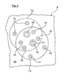
- the Fig. 3 This is also illustrated in a sketch-like representation of the front side 9a of the cylinder crankcase 9 with the outlines of the mounted journal 13.
- the solid line shows the position of the journal 13 in the manufacturing or new state of the internal combustion engine and the dashed line the position after a planning of the sealing surfaces of the Cylinder head 2 and / or the cylinder crankcase 9.
- the outlet point 16 of a lubricating oil channel integrated in the crankcase 9 is provided centrally with respect to the bearing journal 13, into which a centering bushing 17, which is preferably located concentrically in the bearing journal 13, is inserted.
- the centering bushing 17 also protrudes into a corresponding recess of the bearing journal 13, to which a lubricating oil channel (not shown) incorporated in the bearing journal 13 connects for lubrication of the intermediate gearwheel 6.
- the bearing pin 13 is fastened by means of the four fastening screws 14, which are screwed into end-side threaded bores of the crankcase 9 in a corresponding hole pattern.
- the bearing pin 13 (dashed lines) with the intermediate 6 can be implemented in a second, a repair condition corresponding position to compensate for the completed planning by 0.5mm and the correspondingly changed center distances, wherein at the end face 9a a second port point 18 of the lubricating oil passage and a second, corresponding laterally and optionally rotated offset hole pattern of the threaded holes 19 is provided.
- the centering sleeve 17 is removed from the discharge point 16 and inserted into the discharge point 18. How out Fig. 3 it can be seen, the respectively unused opening point 16 or 18 is each directly closed by the bearing pin 13 (but could for example be closed by a grub screw or the like).
- the optionally caused by the offset of the bearing pin 13 and the intermediate gear 6 valve timing change to the camshaft 3 can be compensated by the spur gear 4 is carried out on the camshaft 3 relative to the camshaft 3 adjustable, thereby only a readjustment of the valve timing in a conventional manner is to perform.
- a modified spur gear 4 can be made to the spur gear 4 and mounted in case of repair, the toothing is made out of phase to the extent of fixed predetermined valve timing change.
- the timing gear 5 could then be mounted again practically without additional adjustment effort as in the new state of the internal combustion engine.
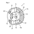
- the intermediate gear 7 as Einstelltechnikrad ( Fig. 4 ), which is composed of two gears 7a, 7b, which are rotatably mounted together on the bearing pin 15 and fastened by means of screws 20 to each other.
- the exemplary only four screws 20 pass through slot-shaped recesses 21 in a gear 7a and cooperate with corresponding threaded holes 22 in the second gear 7b. By loosening the screws 20, the two gears 7a, 7b can be adjusted relative to each other in the circumferential direction.
- a U-shaped lock washer 23 is inserted, which engages radially inwardly into a circumferential groove 15a of the journal 15 and the radially outwardly held in an annular recess 7c of a gear 7a.
- the two gears 7a, 7b are axially fixed captive on the bearing pin 15 and form a pre-assembly as soon as the two gears 7a, 7b are secured by means of screws 20 loosely together.
- the lock washer 23 does not interfere with the free rotation of the Einstelltechnikrads 7 on the journal 15.
- the Steuertrieb 1 can in new condition of the internal combustion engine with a uniform intermediate gear 7 corresponding width (equal to the two gears 7a, 7b) to be executed, in which the valve timing specified constructively is carried out by simply mounting the entire gears 5 to 8, wherein the spur gears 4 and 8 are fixed exactly, for example, via splines to the camshaft 3 and the crankshaft 10.
- the timing gear 1 as an intermediate gear 7 (or possibly as an intermediate gear 6) have the Einstelltechnikrad 7.
- the entire gears 4 to 8 with loose screws 20 are mounted on the adjusting gear 7, then the crankshaft 10 and the camshaft 3 by means of attached markings on the gears 4 and 8 or by using a gauge in a defined angular position to each other (for example OT position of the piston of the cylinder 1) fixed and finally the screws 20 of the Einstell leopardrads 7 tightened.
- control drive 1 is not limited to the illustrated embodiment of the control drive 1.
- AT 001 616 U1 could also be a single-track gear drive with only one idler gear 6 or optionally provided with two intermediate gears 6 and 7.
Landscapes
- Engineering & Computer Science (AREA)
- Mechanical Engineering (AREA)
- General Engineering & Computer Science (AREA)
- Valve Device For Special Equipments (AREA)
- Valve-Gear Or Valve Arrangements (AREA)
Applications Claiming Priority (1)
| Application Number | Priority Date | Filing Date | Title |
|---|---|---|---|
| DE102012009604A DE102012009604A1 (de) | 2012-05-15 | 2012-05-15 | Steuerungsantrieb für eine ventilgesteuerte Brennkraftmaschine |
Publications (2)
| Publication Number | Publication Date |
|---|---|
| EP2664751A1 true EP2664751A1 (fr) | 2013-11-20 |
| EP2664751B1 EP2664751B1 (fr) | 2014-12-10 |
Family
ID=48183976
Family Applications (1)
| Application Number | Title | Priority Date | Filing Date |
|---|---|---|---|
| EP13001882.3A Not-in-force EP2664751B1 (fr) | 2012-05-15 | 2013-04-11 | Distribution pour un moteur à combustion interne commandé par soupape |
Country Status (5)
| Country | Link |
|---|---|
| EP (1) | EP2664751B1 (fr) |
| CN (1) | CN103422927B (fr) |
| BR (1) | BR102013011909B1 (fr) |
| DE (1) | DE102012009604A1 (fr) |
| RU (1) | RU2622358C2 (fr) |
Cited By (1)
| Publication number | Priority date | Publication date | Assignee | Title |
|---|---|---|---|---|
| CN105041467A (zh) * | 2015-06-08 | 2015-11-11 | 张义敏 | 无缸盖双曲轴偏置四冲程卧式内燃机 |
Families Citing this family (3)
| Publication number | Priority date | Publication date | Assignee | Title |
|---|---|---|---|---|
| CN107725131A (zh) * | 2017-11-07 | 2018-02-23 | 重庆润通科技有限公司 | 可调式凸轮驱动机构 |
| CN111684146B (zh) * | 2017-12-13 | 2022-08-05 | 康明斯公司 | 远程安装的中间齿轮 |
| CN110821593B (zh) * | 2018-08-10 | 2023-03-31 | 康明斯公司 | 用于内燃发动机系统的齿轮系 |
Citations (11)
| Publication number | Priority date | Publication date | Assignee | Title |
|---|---|---|---|---|
| US3734073A (en) * | 1971-06-01 | 1973-05-22 | R Walter | Adjustable camshaft sprocket wheel |
| DE2255601A1 (de) * | 1972-11-13 | 1974-05-16 | Kloeckner Humboldt Deutz Ag | Brennkraftmaschine mit zahnradgetriebe zum antrieb der steuerungsteile |
| FR2508973A1 (fr) * | 1981-07-03 | 1983-01-07 | Maschf Augsburg Nuernberg Ag | Prise de couple auxiliaire sur moteur thermique a explosion ou a combustion interne |
| US4747321A (en) * | 1987-07-17 | 1988-05-31 | Lockheed Corporation | Anti-backlash gear assembly |
| WO1993000530A1 (fr) * | 1991-06-24 | 1993-01-07 | Caterpillar Inc. | Mechanisme de reglage du jeu |
| US5540112A (en) * | 1992-05-26 | 1996-07-30 | Caterpillar Inc. | Backlash adjustment mechanism |
| EP0767326A2 (fr) * | 1995-10-03 | 1997-04-09 | Perkins Limited | Méthode et dispositif pour l'ajustement du jeu dans un train d'engrenage |
| AT1616U1 (de) | 1995-08-31 | 1997-08-25 | Avl Verbrennungskraft Messtech | Brennkraftmaschine mit über zahnräder angetriebener nockenwelle |
| DE10154069A1 (de) * | 2001-11-02 | 2003-05-15 | Volkswagen Ag | Stirnrad-Nockenwellenantrieb |
| EP1867861A2 (fr) * | 2006-06-16 | 2007-12-19 | I-TEA S.r.l. | Système de support de roue dentée sur un boîtier d'un moteur à combustion interne |
| US20090084207A1 (en) * | 2007-09-28 | 2009-04-02 | General Electric Company | Split shaft for high power diesel engine |
Family Cites Families (2)
| Publication number | Priority date | Publication date | Assignee | Title |
|---|---|---|---|---|
| SU1663212A2 (ru) * | 1988-12-20 | 1991-07-15 | Научно-исследовательский конструкторско-технологический институт тракторных и комбайновых двигателей | Привод распределительного вала двигател внутреннего сгорани |
| CN101608572A (zh) * | 2009-07-08 | 2009-12-23 | 苏州益方动力机械有限公司 | 一种具有涡轮增压的汽油发动机 |
-
2012
- 2012-05-15 DE DE102012009604A patent/DE102012009604A1/de not_active Ceased
-
2013
- 2013-04-11 EP EP13001882.3A patent/EP2664751B1/fr not_active Not-in-force
- 2013-05-14 RU RU2013122347A patent/RU2622358C2/ru active
- 2013-05-14 BR BR102013011909-1A patent/BR102013011909B1/pt not_active IP Right Cessation
- 2013-05-15 CN CN201310178892.XA patent/CN103422927B/zh active Active
Patent Citations (11)
| Publication number | Priority date | Publication date | Assignee | Title |
|---|---|---|---|---|
| US3734073A (en) * | 1971-06-01 | 1973-05-22 | R Walter | Adjustable camshaft sprocket wheel |
| DE2255601A1 (de) * | 1972-11-13 | 1974-05-16 | Kloeckner Humboldt Deutz Ag | Brennkraftmaschine mit zahnradgetriebe zum antrieb der steuerungsteile |
| FR2508973A1 (fr) * | 1981-07-03 | 1983-01-07 | Maschf Augsburg Nuernberg Ag | Prise de couple auxiliaire sur moteur thermique a explosion ou a combustion interne |
| US4747321A (en) * | 1987-07-17 | 1988-05-31 | Lockheed Corporation | Anti-backlash gear assembly |
| WO1993000530A1 (fr) * | 1991-06-24 | 1993-01-07 | Caterpillar Inc. | Mechanisme de reglage du jeu |
| US5540112A (en) * | 1992-05-26 | 1996-07-30 | Caterpillar Inc. | Backlash adjustment mechanism |
| AT1616U1 (de) | 1995-08-31 | 1997-08-25 | Avl Verbrennungskraft Messtech | Brennkraftmaschine mit über zahnräder angetriebener nockenwelle |
| EP0767326A2 (fr) * | 1995-10-03 | 1997-04-09 | Perkins Limited | Méthode et dispositif pour l'ajustement du jeu dans un train d'engrenage |
| DE10154069A1 (de) * | 2001-11-02 | 2003-05-15 | Volkswagen Ag | Stirnrad-Nockenwellenantrieb |
| EP1867861A2 (fr) * | 2006-06-16 | 2007-12-19 | I-TEA S.r.l. | Système de support de roue dentée sur un boîtier d'un moteur à combustion interne |
| US20090084207A1 (en) * | 2007-09-28 | 2009-04-02 | General Electric Company | Split shaft for high power diesel engine |
Cited By (1)
| Publication number | Priority date | Publication date | Assignee | Title |
|---|---|---|---|---|
| CN105041467A (zh) * | 2015-06-08 | 2015-11-11 | 张义敏 | 无缸盖双曲轴偏置四冲程卧式内燃机 |
Also Published As
| Publication number | Publication date |
|---|---|
| BR102013011909A2 (pt) | 2015-06-30 |
| CN103422927A (zh) | 2013-12-04 |
| CN103422927B (zh) | 2017-04-12 |
| DE102012009604A1 (de) | 2013-11-21 |
| BR102013011909B1 (pt) | 2022-01-18 |
| EP2664751B1 (fr) | 2014-12-10 |
| RU2622358C2 (ru) | 2017-06-14 |
| RU2013122347A (ru) | 2014-11-20 |
Similar Documents
| Publication | Publication Date | Title |
|---|---|---|
| EP3350464B1 (fr) | Engrenage planétaire d'une éolienne avec roues planétaires à paliers lisses | |
| DE102011081483A1 (de) | Verfahren zur vereinfachten und lagegenauen Fixierung eines Nockenwellenmoduls an einem Zylinderkopf | |
| EP2664751B1 (fr) | Distribution pour un moteur à combustion interne commandé par soupape | |
| DE102008052434A1 (de) | Stirnradtrieb für eine Brennkraftmaschine | |
| DE2836094C2 (de) | Anordnung einer Ölpumpe | |
| EP2664752B1 (fr) | Procédé de compensation d'une modification de distance d'axe sur la distribution d'un moteur à combustion interne commandé par soupape et distribution | |
| DE1954456A1 (de) | Ventilmechanismus | |
| DE102009055214A1 (de) | Zahnspieleinstellung bei Zahnrädern | |
| DE102011106565A1 (de) | vollvariable Hubventilsteuerung | |
| DE102011114588A1 (de) | Ventiltrieb für Brennkraftmaschinen mit verstellbarer Nockenwelle | |
| DE102014214125B4 (de) | Stelleinrichtung zur Verstellung von Steuerzeiten einer Brennkraftmaschine | |
| AT524689B1 (de) | Achse | |
| DE102014209312B4 (de) | Nockenwellenverstellanordnung, umfassend eine axiale Sicherung mittels einer Spannhülse | |
| DE102008017046B4 (de) | Mehrteiliges Antriebsrad für einen Zugmitteltrieb | |
| WO2006050545A2 (fr) | Systeme de tete de cylindre destine a un moteur a combustion interne | |
| WO2010009740A2 (fr) | Transmission à pignons en deux parties à propriétés particulières des dentures | |
| EP3510258A1 (fr) | Commande d'arbre à cames variable | |
| DE10002512A1 (de) | Zylinderkopf für eine ventilgesteuerte Brennkraftmaschine | |
| DE102017103985B3 (de) | Wellgenerator | |
| DE102022132998B3 (de) | Brennkraftmaschine mit einem Nockenwellenversteller und Nockenwelle mit einem Nockenwellenversteller | |
| EP1783331B1 (fr) | Système comprenant un arbre à cames d'admission, un arbre à cames d'échappement et un variateur de phase, et utilisation de ce système | |
| DE19747031A1 (de) | Variable Ventilsteuerung für Brennkraftmaschinen | |
| DE102017211074B4 (de) | Verfahren zum Montieren einer Brennkraftmaschine sowie entsprechende Brennkraftmaschine | |
| DE102005034177B3 (de) | Zwangsgesteuerte Ventilantriebsvorrichtung | |
| DE102015016703B4 (de) | Verfahren zum Einstellen einer Zugmitteltriebanordnung |
Legal Events
| Date | Code | Title | Description |
|---|---|---|---|
| PUAI | Public reference made under article 153(3) epc to a published international application that has entered the european phase |
Free format text: ORIGINAL CODE: 0009012 |
|
| AK | Designated contracting states |
Kind code of ref document: A1 Designated state(s): AL AT BE BG CH CY CZ DE DK EE ES FI FR GB GR HR HU IE IS IT LI LT LU LV MC MK MT NL NO PL PT RO RS SE SI SK SM TR |
|
| AX | Request for extension of the european patent |
Extension state: BA ME |
|
| 17P | Request for examination filed |
Effective date: 20140411 |
|
| RIC1 | Information provided on ipc code assigned before grant |
Ipc: F01L 1/02 20060101AFI20140709BHEP Ipc: F16H 57/022 20120101ALI20140709BHEP Ipc: F16H 55/18 20060101ALI20140709BHEP |
|
| GRAP | Despatch of communication of intention to grant a patent |
Free format text: ORIGINAL CODE: EPIDOSNIGR1 |
|
| INTG | Intention to grant announced |
Effective date: 20140821 |
|
| GRAS | Grant fee paid |
Free format text: ORIGINAL CODE: EPIDOSNIGR3 |
|
| GRAA | (expected) grant |
Free format text: ORIGINAL CODE: 0009210 |
|
| AK | Designated contracting states |
Kind code of ref document: B1 Designated state(s): AL AT BE BG CH CY CZ DE DK EE ES FI FR GB GR HR HU IE IS IT LI LT LU LV MC MK MT NL NO PL PT RO RS SE SI SK SM TR |
|
| REG | Reference to a national code |
Ref country code: GB Ref legal event code: FG4D Free format text: NOT ENGLISH |
|
| REG | Reference to a national code |
Ref country code: CH Ref legal event code: EP |
|
| REG | Reference to a national code |
Ref country code: IE Ref legal event code: FG4D Free format text: LANGUAGE OF EP DOCUMENT: GERMAN |
|
| REG | Reference to a national code |
Ref country code: DE Ref legal event code: R096 Ref document number: 502013000222 Country of ref document: DE Effective date: 20150115 Ref country code: AT Ref legal event code: REF Ref document number: 700769 Country of ref document: AT Kind code of ref document: T Effective date: 20150115 |
|
| REG | Reference to a national code |
Ref country code: NL Ref legal event code: T3 |
|
| REG | Reference to a national code |
Ref country code: SE Ref legal event code: TRGR |
|
| PG25 | Lapsed in a contracting state [announced via postgrant information from national office to epo] |
Ref country code: NO Free format text: LAPSE BECAUSE OF FAILURE TO SUBMIT A TRANSLATION OF THE DESCRIPTION OR TO PAY THE FEE WITHIN THE PRESCRIBED TIME-LIMIT Effective date: 20150310 Ref country code: LT Free format text: LAPSE BECAUSE OF FAILURE TO SUBMIT A TRANSLATION OF THE DESCRIPTION OR TO PAY THE FEE WITHIN THE PRESCRIBED TIME-LIMIT Effective date: 20141210 Ref country code: ES Free format text: LAPSE BECAUSE OF FAILURE TO SUBMIT A TRANSLATION OF THE DESCRIPTION OR TO PAY THE FEE WITHIN THE PRESCRIBED TIME-LIMIT Effective date: 20141210 Ref country code: FI Free format text: LAPSE BECAUSE OF FAILURE TO SUBMIT A TRANSLATION OF THE DESCRIPTION OR TO PAY THE FEE WITHIN THE PRESCRIBED TIME-LIMIT Effective date: 20141210 |
|
| REG | Reference to a national code |
Ref country code: LT Ref legal event code: MG4D |
|
| PG25 | Lapsed in a contracting state [announced via postgrant information from national office to epo] |
Ref country code: RS Free format text: LAPSE BECAUSE OF FAILURE TO SUBMIT A TRANSLATION OF THE DESCRIPTION OR TO PAY THE FEE WITHIN THE PRESCRIBED TIME-LIMIT Effective date: 20141210 Ref country code: LV Free format text: LAPSE BECAUSE OF FAILURE TO SUBMIT A TRANSLATION OF THE DESCRIPTION OR TO PAY THE FEE WITHIN THE PRESCRIBED TIME-LIMIT Effective date: 20141210 Ref country code: GR Free format text: LAPSE BECAUSE OF FAILURE TO SUBMIT A TRANSLATION OF THE DESCRIPTION OR TO PAY THE FEE WITHIN THE PRESCRIBED TIME-LIMIT Effective date: 20150311 Ref country code: HR Free format text: LAPSE BECAUSE OF FAILURE TO SUBMIT A TRANSLATION OF THE DESCRIPTION OR TO PAY THE FEE WITHIN THE PRESCRIBED TIME-LIMIT Effective date: 20141210 |
|
| PG25 | Lapsed in a contracting state [announced via postgrant information from national office to epo] |
Ref country code: CZ Free format text: LAPSE BECAUSE OF FAILURE TO SUBMIT A TRANSLATION OF THE DESCRIPTION OR TO PAY THE FEE WITHIN THE PRESCRIBED TIME-LIMIT Effective date: 20141210 Ref country code: EE Free format text: LAPSE BECAUSE OF FAILURE TO SUBMIT A TRANSLATION OF THE DESCRIPTION OR TO PAY THE FEE WITHIN THE PRESCRIBED TIME-LIMIT Effective date: 20141210 Ref country code: PT Free format text: LAPSE BECAUSE OF FAILURE TO SUBMIT A TRANSLATION OF THE DESCRIPTION OR TO PAY THE FEE WITHIN THE PRESCRIBED TIME-LIMIT Effective date: 20150410 Ref country code: SK Free format text: LAPSE BECAUSE OF FAILURE TO SUBMIT A TRANSLATION OF THE DESCRIPTION OR TO PAY THE FEE WITHIN THE PRESCRIBED TIME-LIMIT Effective date: 20141210 Ref country code: RO Free format text: LAPSE BECAUSE OF FAILURE TO SUBMIT A TRANSLATION OF THE DESCRIPTION OR TO PAY THE FEE WITHIN THE PRESCRIBED TIME-LIMIT Effective date: 20141210 |
|
| PG25 | Lapsed in a contracting state [announced via postgrant information from national office to epo] |
Ref country code: PL Free format text: LAPSE BECAUSE OF FAILURE TO SUBMIT A TRANSLATION OF THE DESCRIPTION OR TO PAY THE FEE WITHIN THE PRESCRIBED TIME-LIMIT Effective date: 20141210 Ref country code: IS Free format text: LAPSE BECAUSE OF FAILURE TO SUBMIT A TRANSLATION OF THE DESCRIPTION OR TO PAY THE FEE WITHIN THE PRESCRIBED TIME-LIMIT Effective date: 20150410 |
|
| REG | Reference to a national code |
Ref country code: DE Ref legal event code: R097 Ref document number: 502013000222 Country of ref document: DE |
|
| PLBE | No opposition filed within time limit |
Free format text: ORIGINAL CODE: 0009261 |
|
| STAA | Information on the status of an ep patent application or granted ep patent |
Free format text: STATUS: NO OPPOSITION FILED WITHIN TIME LIMIT |
|
| PG25 | Lapsed in a contracting state [announced via postgrant information from national office to epo] |
Ref country code: DK Free format text: LAPSE BECAUSE OF FAILURE TO SUBMIT A TRANSLATION OF THE DESCRIPTION OR TO PAY THE FEE WITHIN THE PRESCRIBED TIME-LIMIT Effective date: 20141210 |
|
| 26N | No opposition filed |
Effective date: 20150911 |
|
| PG25 | Lapsed in a contracting state [announced via postgrant information from national office to epo] |
Ref country code: MC Free format text: LAPSE BECAUSE OF FAILURE TO SUBMIT A TRANSLATION OF THE DESCRIPTION OR TO PAY THE FEE WITHIN THE PRESCRIBED TIME-LIMIT Effective date: 20141210 Ref country code: LU Free format text: LAPSE BECAUSE OF FAILURE TO SUBMIT A TRANSLATION OF THE DESCRIPTION OR TO PAY THE FEE WITHIN THE PRESCRIBED TIME-LIMIT Effective date: 20150411 |
|
| REG | Reference to a national code |
Ref country code: IE Ref legal event code: MM4A |
|
| PG25 | Lapsed in a contracting state [announced via postgrant information from national office to epo] |
Ref country code: SI Free format text: LAPSE BECAUSE OF FAILURE TO SUBMIT A TRANSLATION OF THE DESCRIPTION OR TO PAY THE FEE WITHIN THE PRESCRIBED TIME-LIMIT Effective date: 20141210 |
|
| REG | Reference to a national code |
Ref country code: FR Ref legal event code: PLFP Year of fee payment: 4 |
|
| PG25 | Lapsed in a contracting state [announced via postgrant information from national office to epo] |
Ref country code: IE Free format text: LAPSE BECAUSE OF NON-PAYMENT OF DUE FEES Effective date: 20150411 |
|
| REG | Reference to a national code |
Ref country code: CH Ref legal event code: PL |
|
| PG25 | Lapsed in a contracting state [announced via postgrant information from national office to epo] |
Ref country code: MT Free format text: LAPSE BECAUSE OF FAILURE TO SUBMIT A TRANSLATION OF THE DESCRIPTION OR TO PAY THE FEE WITHIN THE PRESCRIBED TIME-LIMIT Effective date: 20141210 |
|
| PG25 | Lapsed in a contracting state [announced via postgrant information from national office to epo] |
Ref country code: LI Free format text: LAPSE BECAUSE OF NON-PAYMENT OF DUE FEES Effective date: 20160430 Ref country code: CH Free format text: LAPSE BECAUSE OF NON-PAYMENT OF DUE FEES Effective date: 20160430 |
|
| REG | Reference to a national code |
Ref country code: FR Ref legal event code: PLFP Year of fee payment: 5 |
|
| PG25 | Lapsed in a contracting state [announced via postgrant information from national office to epo] |
Ref country code: HU Free format text: LAPSE BECAUSE OF FAILURE TO SUBMIT A TRANSLATION OF THE DESCRIPTION OR TO PAY THE FEE WITHIN THE PRESCRIBED TIME-LIMIT; INVALID AB INITIO Effective date: 20130411 Ref country code: BG Free format text: LAPSE BECAUSE OF FAILURE TO SUBMIT A TRANSLATION OF THE DESCRIPTION OR TO PAY THE FEE WITHIN THE PRESCRIBED TIME-LIMIT Effective date: 20141210 |
|
| PG25 | Lapsed in a contracting state [announced via postgrant information from national office to epo] |
Ref country code: CY Free format text: LAPSE BECAUSE OF FAILURE TO SUBMIT A TRANSLATION OF THE DESCRIPTION OR TO PAY THE FEE WITHIN THE PRESCRIBED TIME-LIMIT Effective date: 20141210 |
|
| PG25 | Lapsed in a contracting state [announced via postgrant information from national office to epo] |
Ref country code: BE Free format text: LAPSE BECAUSE OF NON-PAYMENT OF DUE FEES Effective date: 20150430 |
|
| PG25 | Lapsed in a contracting state [announced via postgrant information from national office to epo] |
Ref country code: TR Free format text: LAPSE BECAUSE OF FAILURE TO SUBMIT A TRANSLATION OF THE DESCRIPTION OR TO PAY THE FEE WITHIN THE PRESCRIBED TIME-LIMIT Effective date: 20141210 |
|
| GBPC | Gb: european patent ceased through non-payment of renewal fee |
Effective date: 20170411 |
|
| PG25 | Lapsed in a contracting state [announced via postgrant information from national office to epo] |
Ref country code: GB Free format text: LAPSE BECAUSE OF NON-PAYMENT OF DUE FEES Effective date: 20170411 |
|
| REG | Reference to a national code |
Ref country code: FR Ref legal event code: PLFP Year of fee payment: 6 |
|
| PG25 | Lapsed in a contracting state [announced via postgrant information from national office to epo] |
Ref country code: SM Free format text: LAPSE BECAUSE OF FAILURE TO SUBMIT A TRANSLATION OF THE DESCRIPTION OR TO PAY THE FEE WITHIN THE PRESCRIBED TIME-LIMIT Effective date: 20141210 |
|
| PG25 | Lapsed in a contracting state [announced via postgrant information from national office to epo] |
Ref country code: MK Free format text: LAPSE BECAUSE OF FAILURE TO SUBMIT A TRANSLATION OF THE DESCRIPTION OR TO PAY THE FEE WITHIN THE PRESCRIBED TIME-LIMIT Effective date: 20141210 |
|
| PG25 | Lapsed in a contracting state [announced via postgrant information from national office to epo] |
Ref country code: AL Free format text: LAPSE BECAUSE OF FAILURE TO SUBMIT A TRANSLATION OF THE DESCRIPTION OR TO PAY THE FEE WITHIN THE PRESCRIBED TIME-LIMIT Effective date: 20141210 |
|
| REG | Reference to a national code |
Ref country code: AT Ref legal event code: MM01 Ref document number: 700769 Country of ref document: AT Kind code of ref document: T Effective date: 20180411 |
|
| REG | Reference to a national code |
Ref country code: DE Ref legal event code: R081 Ref document number: 502013000222 Country of ref document: DE Owner name: MAN TRUCK & BUS SE, DE Free format text: FORMER OWNER: MAN TRUCK & BUS AG, 80995 MUENCHEN, DE |
|
| PG25 | Lapsed in a contracting state [announced via postgrant information from national office to epo] |
Ref country code: AT Free format text: LAPSE BECAUSE OF NON-PAYMENT OF DUE FEES Effective date: 20180411 |
|
| PGFP | Annual fee paid to national office [announced via postgrant information from national office to epo] |
Ref country code: NL Payment date: 20240425 Year of fee payment: 12 |
|
| PGFP | Annual fee paid to national office [announced via postgrant information from national office to epo] |
Ref country code: DE Payment date: 20240429 Year of fee payment: 12 |
|
| PGFP | Annual fee paid to national office [announced via postgrant information from national office to epo] |
Ref country code: IT Payment date: 20240423 Year of fee payment: 12 Ref country code: FR Payment date: 20240430 Year of fee payment: 12 |
|
| PGFP | Annual fee paid to national office [announced via postgrant information from national office to epo] |
Ref country code: SE Payment date: 20240429 Year of fee payment: 12 |
|
| REG | Reference to a national code |
Ref country code: DE Ref legal event code: R119 Ref document number: 502013000222 Country of ref document: DE |
|
| REG | Reference to a national code |
Ref country code: SE Ref legal event code: EUG |
|
| REG | Reference to a national code |
Ref country code: NL Ref legal event code: MM Effective date: 20250501 |
|
| PG25 | Lapsed in a contracting state [announced via postgrant information from national office to epo] |
Ref country code: DE Free format text: LAPSE BECAUSE OF NON-PAYMENT OF DUE FEES Effective date: 20251104 |
|
| PG25 | Lapsed in a contracting state [announced via postgrant information from national office to epo] |
Ref country code: NL Free format text: LAPSE BECAUSE OF NON-PAYMENT OF DUE FEES Effective date: 20250501 Ref country code: FR Free format text: LAPSE BECAUSE OF NON-PAYMENT OF DUE FEES Effective date: 20250430 |
|
| PG25 | Lapsed in a contracting state [announced via postgrant information from national office to epo] |
Ref country code: SE Free format text: LAPSE BECAUSE OF NON-PAYMENT OF DUE FEES Effective date: 20250412 |
|
| PG25 | Lapsed in a contracting state [announced via postgrant information from national office to epo] |
Ref country code: IT Free format text: LAPSE BECAUSE OF NON-PAYMENT OF DUE FEES Effective date: 20250411 |