EP2664804A2 - Régulateur de pression et de débit, unité de réglage pour une machine de refoulement hydraulique réglable dotée d'un régulateur de pression et de débit et procédé de régulation d'une telle unité de réglage - Google Patents
Régulateur de pression et de débit, unité de réglage pour une machine de refoulement hydraulique réglable dotée d'un régulateur de pression et de débit et procédé de régulation d'une telle unité de réglage Download PDFInfo
- Publication number
- EP2664804A2 EP2664804A2 EP13002058.9A EP13002058A EP2664804A2 EP 2664804 A2 EP2664804 A2 EP 2664804A2 EP 13002058 A EP13002058 A EP 13002058A EP 2664804 A2 EP2664804 A2 EP 2664804A2
- Authority
- EP
- European Patent Office
- Prior art keywords
- pressure
- switching
- adjusting unit
- flow regulator
- switching valve
- Prior art date
- Legal status (The legal status is an assumption and is not a legal conclusion. Google has not performed a legal analysis and makes no representation as to the accuracy of the status listed.)
- Withdrawn
Links
- 238000006073 displacement reaction Methods 0.000 title claims abstract description 83
- 238000000034 method Methods 0.000 title claims abstract description 19
- 238000005070 sampling Methods 0.000 claims description 32
- 230000004044 response Effects 0.000 claims description 5
- 230000010349 pulsation Effects 0.000 description 14
- 238000006243 chemical reaction Methods 0.000 description 10
- 230000001276 controlling effect Effects 0.000 description 8
- 238000010586 diagram Methods 0.000 description 8
- 238000009499 grossing Methods 0.000 description 8
- 230000008859 change Effects 0.000 description 6
- 230000001419 dependent effect Effects 0.000 description 6
- 238000001914 filtration Methods 0.000 description 6
- 230000001105 regulatory effect Effects 0.000 description 6
- 230000003247 decreasing effect Effects 0.000 description 5
- 230000004043 responsiveness Effects 0.000 description 5
- 230000008901 benefit Effects 0.000 description 4
- 238000012937 correction Methods 0.000 description 4
- 230000008569 process Effects 0.000 description 4
- 238000012546 transfer Methods 0.000 description 4
- 230000005540 biological transmission Effects 0.000 description 3
- 230000009257 reactivity Effects 0.000 description 3
- 230000004913 activation Effects 0.000 description 2
- 230000000454 anti-cipatory effect Effects 0.000 description 2
- 238000013459 approach Methods 0.000 description 2
- 239000012530 fluid Substances 0.000 description 2
- 238000013021 overheating Methods 0.000 description 2
- 230000009467 reduction Effects 0.000 description 2
- 238000012935 Averaging Methods 0.000 description 1
- 230000003321 amplification Effects 0.000 description 1
- 238000010276 construction Methods 0.000 description 1
- 238000013016 damping Methods 0.000 description 1
- 230000001934 delay Effects 0.000 description 1
- 230000003111 delayed effect Effects 0.000 description 1
- 238000012217 deletion Methods 0.000 description 1
- 230000037430 deletion Effects 0.000 description 1
- 238000013461 design Methods 0.000 description 1
- 230000001627 detrimental effect Effects 0.000 description 1
- 238000011161 development Methods 0.000 description 1
- 230000018109 developmental process Effects 0.000 description 1
- 238000011982 device technology Methods 0.000 description 1
- 210000003746 feather Anatomy 0.000 description 1
- 238000012423 maintenance Methods 0.000 description 1
- 238000004519 manufacturing process Methods 0.000 description 1
- 238000005259 measurement Methods 0.000 description 1
- 230000007246 mechanism Effects 0.000 description 1
- 238000003199 nucleic acid amplification method Methods 0.000 description 1
- 230000010355 oscillation Effects 0.000 description 1
- 230000010363 phase shift Effects 0.000 description 1
- 238000010791 quenching Methods 0.000 description 1
- 230000000171 quenching effect Effects 0.000 description 1
- 230000003014 reinforcing effect Effects 0.000 description 1
- 230000002441 reversible effect Effects 0.000 description 1
- 230000000630 rising effect Effects 0.000 description 1
- 230000035939 shock Effects 0.000 description 1
- 230000001360 synchronised effect Effects 0.000 description 1
- 230000001960 triggered effect Effects 0.000 description 1
Images




Classifications
-
- F—MECHANICAL ENGINEERING; LIGHTING; HEATING; WEAPONS; BLASTING
- F04—POSITIVE - DISPLACEMENT MACHINES FOR LIQUIDS; PUMPS FOR LIQUIDS OR ELASTIC FLUIDS
- F04B—POSITIVE-DISPLACEMENT MACHINES FOR LIQUIDS; PUMPS
- F04B49/00—Control, e.g. of pump delivery, or pump pressure of, or safety measures for, machines, pumps, or pumping installations, not otherwise provided for, or of interest apart from, groups F04B1/00 - F04B47/00
- F04B49/002—Hydraulic systems to change the pump delivery
-
- F—MECHANICAL ENGINEERING; LIGHTING; HEATING; WEAPONS; BLASTING
- F15—FLUID-PRESSURE ACTUATORS; HYDRAULICS OR PNEUMATICS IN GENERAL
- F15B—SYSTEMS ACTING BY MEANS OF FLUIDS IN GENERAL; FLUID-PRESSURE ACTUATORS, e.g. SERVOMOTORS; DETAILS OF FLUID-PRESSURE SYSTEMS, NOT OTHERWISE PROVIDED FOR
- F15B11/00—Servomotor systems without provision for follow-up action; Circuits therefor
- F15B11/02—Systems essentially incorporating special features for controlling the speed or actuating force of an output member
- F15B11/04—Systems essentially incorporating special features for controlling the speed or actuating force of an output member for controlling the speed
- F15B11/05—Systems essentially incorporating special features for controlling the speed or actuating force of an output member for controlling the speed specially adapted to maintain constant speed, e.g. pressure-compensated, load-responsive
- F15B11/055—Systems essentially incorporating special features for controlling the speed or actuating force of an output member for controlling the speed specially adapted to maintain constant speed, e.g. pressure-compensated, load-responsive by adjusting the pump output or bypass
-
- F—MECHANICAL ENGINEERING; LIGHTING; HEATING; WEAPONS; BLASTING
- F15—FLUID-PRESSURE ACTUATORS; HYDRAULICS OR PNEUMATICS IN GENERAL
- F15B—SYSTEMS ACTING BY MEANS OF FLUIDS IN GENERAL; FLUID-PRESSURE ACTUATORS, e.g. SERVOMOTORS; DETAILS OF FLUID-PRESSURE SYSTEMS, NOT OTHERWISE PROVIDED FOR
- F15B2211/00—Circuits for servomotor systems
- F15B2211/20—Fluid pressure source, e.g. accumulator or variable axial piston pump
- F15B2211/205—Systems with pumps
- F15B2211/2053—Type of pump
- F15B2211/20546—Type of pump variable capacity
- F15B2211/20553—Type of pump variable capacity with pilot circuit, e.g. for controlling a swash plate
Definitions
- the invention is based on a pressure-flow regulator for adjusting an adjustment of an adjustable hydraulic displacement machine. Furthermore, the invention is based on an adjusting unit for such a displacement machine with such a pressure-flow regulator and on a method for controlling the adjusting unit.
- an adjustable positive displacement machine in the form of a hydraulic pump. Their swing angle can be changed via two actuating cylinders.
- a pressure-flow regulator is provided for adjusting the adjusting cylinder and thus for adjusting the pivot angle of the displacement machine.
- This has two proportional valves, via which a cylinder space of the adjusting cylinder can be connected to a pressure line connected to the displacement machine or to a tank line.
- the proportional valves are hydraulically actuated.
- a disadvantage of such a pressure-flow regulator is that the proportional valves are relatively expensive and have a low robustness. Furthermore, a leakage of the proportional valves is comparatively high, which leads to a loss of efficiency of the positive displacement machine.
- the invention has the object to provide a pressure-flow regulator for adjusting an adjustment, which eliminates the disadvantages mentioned above.
- Another object of the invention is an adjustment unit for an adjustable To provide hydraulic displacement machine with such a pressure-flow regulator, which also eliminates the disadvantages mentioned.
- a pressure-conveying flow regulator for adjusting an adjusting unit of an adjustable hydraulic displacement machine has a switching valve for actuating the adjusting unit.
- This solution has the advantage that the pressure-flow regulator is relatively inexpensive due to the switching valve, since a switching valve has comparatively low production costs and is simple in terms of device technology. A leakage of the pressure-flow regulator is also relatively low due to the switching valve. Furthermore, switching valves have a very short positioning time, which is why the pressure-flow regulator also has a very short positioning time. Due to the robust switching valve, the pressure flow regulator has a high shock resistance. Due to a low susceptibility of the switching valves against soiled hydraulic fluid maintenance of the pressure-flow regulator is low. A change in the switching behavior of the switching valves due to temperature changes is also very low compared to proportional valves, whereby the pressure-flow regulator can be used safely at different temperatures. Switch valves are also very robust against electromagnetic interference. Further, it is possible to control the switching valves of the pressure-flow regulator directly via a digital control unit or a mobile controller, in contrast to the prior art, where a digital / analog converter is necessary to control the proportional valves.
- the switching valves are, for example, 2/2-way valves, via which a pressure fluid connection is up and is zuu Kunststoffbar.
- the switching valve may be configured as a slide valve or preferably as a virtually leak-free seat valve.
- a valve body of the switching valves is acted upon in the direction of a closed position with a spring force of a valve spring and can be acted upon via an electromagnetic actuator in the direction of an opening position with an opening force.
- the at least one switching valve can be used flexibly in pulse width modulated mode (PWM) or in ballistic mode (BaM). Thus, different opening cross-sections can be provided in the switching valve.
- PWM pulse width modulated mode
- BaM ballistic mode
- At least one switching valve for controlling a connection between the adjusting unit and a pressure medium source and at least one switching valve for controlling a connection between the adjusting unit and a pressure medium sink is provided.
- a setting cylinder of the adjustment can be adjusted in a simple manner.
- the switching valves for controlling a pressure medium connection between the pressure medium source and the adjusting unit or the pressure medium sink and the adjusting unit can be controlled in the meter-in / meter-out mode (MIO).
- MIO meter-in / meter-out mode
- At least two switching valves are provided in a pressure medium flow path between the adjustment unit and the pressure medium source and / or between the adjustment unit and the pressure medium sink.
- the switching valves of a pressure medium flow path in this case preferably have different nominal sizes in order to use them precisely in pulse-code-modulated mode.
- the larger switching valve can be used, for example, for coarse adjustment of the adjusting cylinder of the adjustment and the smaller switching valve for fine adjustment of the actuating cylinder.
- an adjusting unit for an adjustable hydraulic displacement machine has a pressure-flow regulator according to the invention.
- the adjustment here has at least one actuating cylinder for adjusting a displacement of the Displacement machine, in particular for setting a swivel angle.
- the actuating cylinder has a piston space limited by a cylinder, which is displaceable for displacing the piston in the direction of increasing cylinder space via the switching valve of the pressure-flow regulator with a tapped by a pressure line of the positive displacement pressure medium and the discharge of pressure medium from the cylinder chamber another switching valve with the pressure medium sink is connectable.
- a displacement of the positive displacement machine is increased and reduced when moving in the reverse direction.
- the piston of the adjusting cylinder is acted upon by a spring with a spring force in the direction of the decreasing cylinder space.
- a second actuating cylinder which has a piston defining a cylinder space.
- the cylinder chamber can in this case be connected to the pressure line of the displacement machine.
- the piston then counteracts, for example, the piston of the first actuating cylinder.
- the displacement machine can be an axial piston machine of swash plate construction, wherein the pistons of the actuating cylinder then engage a swash plate for controlling the displacement of the displacement machine.
- an electronic control unit which controls the switching valves as a function of a pressure, in particular in the pressure line of the positive displacement machine, and / or as a function of a displacement path of the piston of the actuating cylinder or a swivel angle of the swash plate.
- a pressure sensor is preferably provided, which taps this in the pressure line of the displacement machine.
- a displacement transducer can be used which measures a displacement path of the piston of the actuating cylinder.
- an overflow valve can be provided, which can be arranged fluidically parallel to at least one switching valve arranged between the pressure line and the cylinder space of the adjusting cylinder.
- the overflow valve is, for example, a non-return valve which opens in the direction of flow toward the cylinder chamber.
- the switching valves are easily controlled, for example, with a three-step control.
- the switching valves can be regulated in a pressure-dependent manner, in particular as a function of a pressure in the pressure line or of a load pressure. It is also conceivable to regulate the actuating cylinder path-dependent from the displacement of the piston.
- a switching cycle of the switching valve may have a predetermined ratio of a turn-on to a turn-off duration.
- D. h. The switching valve is energized with a certain period of time and is energized with an adjoining period of time.
- a switching frequency of these is the same.
- a sampling of the pressure and / or the displacement with a certain sampling frequency may be approximately synchronous with a control of the switching valves with a certain switching frequency, resulting in a very simple control.
- the sampling frequency is a multiple of the switching frequency or corresponds to the switching frequency. Due to the switching frequency, a control pulse is delivered to the switching valves only at predetermined time intervals.
- sampling frequency and the switching frequency do not run synchronously, which makes it possible that the switching frequency is triggered only when needed, while a sampling of the pressure and / or the displacement takes place with a certain sampling frequency.
- the sampling frequency is greater than the switching frequency, which means that during the energization of the switching valve, the pressure and / or the displacement is further scanned and, if necessary, a duty cycle of the energized valve can be interrupted.
- the duty cycle of the switching valves is variable during a switching cycle. The switching valve can close prematurely, if, for example, the measured pressure requires this.
- the switching cycles of the switching valves are independent of each other, whereby the switching valves are thus independently controllable and thus can switch independently.
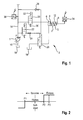
- FIG. 1 a hydraulic circuit diagram with an adjustable displacement machine 1 is shown.
- This can be an axial or radial piston machine, which can be used as a hydraulic pump or hydraulic motor.
- a positioning cylinder 2 is provided for pivoting the swash plate of the displacement machine 1, not shown.
- This has one of a piston 4 limited cylinder space 6.
- the piston is connected via a one-sided piston rod 8 with the swash plate of the displacement machine 1, not shown.
- a displacement of the piston 4 in the direction of an increasing cylinder chamber 6 causes the swash plate is pivoted in the direction of increasing the displacement of the displacement machine 1.
- a displacement of the piston 4 in the direction of the decreasing cylinder space 6 leads to a pivoting of the swash plate in the direction of decreasing displacement of the displacement machine 1.
- a return spring 10 which is arranged in a penetrated by the piston rod 8 annular space 12 of the actuating cylinder 2 is, the piston 4 is acted upon in the direction of the decreasing cylinder space 6 with a spring force.
- a pressure line 14 is connected to a pressure port P and a tank line 16 is connected to a tank port T.
- the pressure line 14 is connected to a hydraulic consumer, not shown.
- the tank line 16 opens into a tank 18.
- the cylinder chamber 6 is connected to the tank line 14 via a first and second switching valve 20 and 22, respectively.
- the switching valves 20 and 22 are arranged fluidically in parallel and each control a pressure medium connection between the cylinder chamber 6 and the pressure line 14.
- Upper switching valve 20 in this case has a larger nominal size than the lower switching valve 22. Fluidically seen between the smaller switching valve 22 and the cylinder chamber 6, a throttle 24 is provided.
- an overflow valve 26 is disposed between the pressure line 14 and the cylinder chamber 6. This is a non-return valve opening in a pressure medium flow direction to the cylinder chamber 6.
- a further switching valve 28 is provided, with which a pressure medium connection between the cylinder chamber 6 and the tank 18 is on and zu bracketbar.
- the switching valves 20, 22 and 28 are designed as 2/2-way valves.
- a valve body of the switching valves 20, 22 and 28 is in this case acted upon via a valve spring 30 in the direction of a closed position with a spring force and with a force against the spring force in the direction of an opening position via an electromagnetic actuator 32nd acted upon.
- the switching valves 20, 22 and 28 are thus closed in the de-energized state.
- the switching valve has a flow direction and has an opening cross-section of, for example, 3.34 mm 2 , for example, at a valve lift of 0.2 mm. In the case of a pressure difference of 90 bar applied to the switching valve, for example, a flow rate of 20 l / min results.
- the pull-in and fall times amount to, for example, about 0.3 ms.
- the relative duty cycle ratio of energized state to de-energized phase
- the switching valve may be designed, for example, to about 10 9 switching cycles.
- a displacement sensor 34 is provided for measuring a displacement path of the piston 4 and the piston rod 8 of the adjusting cylinder 2. This measures the displacement with a certain sampling frequency and reports this to an electronic control unit, not shown. Furthermore, a pressure sensor 36 is provided, with which the pressure in the pressure line 14 is measured and also reported to the electronic control unit. The measurement of the pressure takes place here also with a certain sampling frequency.
- the electronic control unit is preferably designed specifically.
- This is, for example, an output stage electronics in which each electronic card in the European format, two programmable electronic components are located, which can generate a special current waveform.
- four switching valves can be controlled via a respective electronic component, which is, for example, the type CJ840.
- the CJ840 devices can be programmed in an application-oriented manner via an SPI bus.
- the output variables are in particular a maximum voltage of 65 volts and current peaks of up to 12 amps possible.
- the control is usually done via a microcontroller, which is why working with voltage levels based on TTL.
- the basic control concept for a digital pressure control of the displacement machine 1 can be described as a regulation with three-point behavior, see FIG. 2 ,
- the upper (switch-on) point (P2) in FIG. 2 marks the limit for activation of the large switching valve 20.
- the lower point (P1) causes the activation of the output-side switching valve 28. Between the switching points is the so-called dead zone of the control.
- the deadband can also be seen as a tolerance range for the control deviation, as the scheme
- Deviations within this range are tolerated. In this dead zone, the control pauses until the controlled variable exceeds a switching point due to interference, etc. again. With an additional small switching valve 22 for the fine metering receives this three-step control an extension.
- the initial idea is that the small switching valve 22 is designed to attenuate over-switching overshoots caused by the large switching valve 20 with combined switching.
- the switching valve 20, responsible for the coarse dosing (and thus for the rapid filling of the cylinder chamber 6) should be deactivated earlier and the balance of the remaining deviation takes over the small switching valve 22. So this remains activated until the actual switch-on (P2) while the switching point for the large switching valve 22 (P3) is set higher.
- the control via the switching valves 20, 22 and 28 has a three-point behavior.
- the three-step control therefore does not act with a single actuator, which executes the input, off and hold phases. Rather, the adjustment system as a whole, consisting of three actuators and the adjusting mechanism of the displacement machine 1, this behavior.
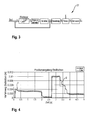
- FIGS. 3 and 4 In a first regulatory procedure is according to FIGS. 3 and 4 the positive displacement machine 1 off FIG. 1 controlled in response to the displacement of the piston 4, wherein the displacement is detected by the transducer 34.
- the three-position controller controls actuators in the form of switching valves 20, 22 and 28, see FIG. 1 , with a control size u.
- This leads to a correcting variable y for the actuating piston and piston 4 of the servo cylinder 2.
- This then results in the displacement of the piston 4 as a "controlled variable distance s", from which, together with a "command path s to" a control error e for the Three-position controller is determined.
- the pivoting cradle or swashplate of the displacement machine 1 is turned off FIG. 1 controlled, which leads to a swivel angle ⁇ for the engine of the displacement machine 1.
- This results in a certain volume flow Q, which is led to the consumer, which can be reacted to a pressure p of the consumer.
- the pivot angle changes proportionally to the change in position of the piston 4, resulting in a changed flow.
- the piston 4 is to be brought into a predetermined position via the filling of the cylinder chamber 6 by means of the switching valves 20, 22, 28.
- the FIG. 4 shows how the piston position follows the setpoint as a controlled variable.
- a sawtooth curve of the controlled variable can be seen.
- This course results from the sudden filling via the switching valves 20, 22 (rising flanks) and the emptying through the switching valve 28 (falling flanks) or the leakage via the piston 4 (slightly sloping course).
- the switching valves 20, 22, 28 are switched with a fixed duty cycle of 20% (maximum possible duty cycle), overshoots resulting from overdoses result in the process.
- the small switching valve 22, as a throttled inlet valve for the fine metering are used.
- the sampling of the control variable is made only at the beginning of the switching cycle (for example, with a switching frequency of 10 Hz). Therefore, in FIG. 4 correspondingly detect late reactions of the controlled variable to changes in the reference variable. All switching valves 20, 22, 28 are driven with the same timing and duty cycle. This means that no matter which switching valve 20, 22, 28 has switched, all follow the pause phase of 80% relative to the switching period duration, even if in the meantime a switching valve 20, 22, 28 would have to respond ausregelnd that has not previously switched. This need not be a significant disadvantage, since a common switching of switching valves 20 or 22 and 28 is usually not necessary. As already stated above, the switching frequency of the switching valves 20, 22 and 28 is 10 hertz. A sampling frequency of the displacement sensor 34 FIG. 1 is also 10 hertz.
- FIG. 5 is in a further control method instead of the displacement of the piston 4, the pressure in the pressure line 14 from FIG. 1 detected as a controlled variable from the pressure sensor 36.
- FIG. 6 is considered the control method with controlled variables without additional interference influences (eg by pulsation, etc.).
- the setpoint is set to 100 bar, for example.
- the switching frequency of the switching valves 20, 22, 28 has, for example, 10 Hz.
- the state of the controlled variable that switching valve 20, 22, 28 is switched to the beginning of the switching cycle, which is required to adjust the control variable again the reference variable.
- the same timing and switching cycle generation takes place for all switching valves 20, 22, 28.
- the spill valve 36 offers FIG. 1 a protection against too high pressure peaks.
- the overflow valve 36 works like a safety valve. It causes an addition to the switching valve 20, 22 taking place filling the adjusting chamber when the pressure has exceeded a certain limit.
- the switch-on times of the switching valves 20, 22 and 28 are variably adjustable. That is, the switching valves 20, 22, 28 can switch off earlier if required, before the maximum possible duty cycle is reached. This takes place in that after the necessary switching of a switching valve 20, 22, 28 in the sampling cycle, the control variable is queried and if necessary (depending on the result of the query), the switching valve is switched off again.
- the sampling frequency is preferably 1 kHz. It will continue the small switching valve 22 used for fine metering. However, thanks to the variably adjustable switch-on duration of the large switching valve 20, this is only necessary for the intervalwise replenishment of the leakage.
- the limits of the controller dead zone (switching points), see FIG. 2 for example, are set to 5 bar above and 10 bar below the setpoint.
- FIG. 6 shows how after an initial increase in pressure, see reference numeral 1, by load increase the spill valve 26 secures the system against a pressure increase of more than 25% above the setpoint (100 bar), see reference numeral 2.
- setpoint 100 bar
- FIG. 6 shows how after an initial increase in pressure, see reference numeral 1, by load increase the spill valve 26 secures the system against a pressure increase of more than 25% above the setpoint (100 bar), see reference numeral 2.
- the subsequent increase in pressure see reference numeral 3 is the result of the leakage over the piston 4, which has the slow emptying of the cylinder chamber 4 result.
- the control variable has risen above the upper switching point of the large switching valve 20, see reference numeral 4, due to the leakage.
- the switching of the switching valve 20 causes a drop in pressure.
- the controlled variable is still within the dead zone of the controller. Only the active at each beginning of the switching cycles subsequent metering of the leakage through the small switching valve 22 causes an adjustment of the pressure curve to the reference variable, see reference numeral 5.
- the scheme can only with the delay of Switching cycle respond, see reference numeral 7.
- the second load increase (noticeable by the increasing uncontrolled pressure) causes further deviations of the controlled variable, up to the pressure limit of the spill valve 26, see reference numeral 8th
- variable duty cycle contributes significantly to increase the responsiveness and accuracy of the pressure curve. It can even be dispensed with the small switching valve 22 in terms of the function for reducing overdoses. For the fine dosage, however, it is still used. The aspect of loss reduction in tax oil remains positive.
- FIG. 7 a control method of a pressure control of the displacer unit 1 with a "nested switching cycle" described.
- the following does not use a rigid switching cycle.
- a new switching cycle starts and at the beginning no Switching is required, not another switching cycle is completely paused, but asked from this point in the sampling clock of, for example, 1 kHz for a necessary switching request. If then, after a few query times switching of the switching valves 20, 22, 28 is necessary, then the normal switching cycle is traversed, with the required duty cycle and the necessary pause ratio.
- FIG. 7 It can be seen that, for example, a reaction of the switching valve 20 takes place already a few milliseconds before the time 500 ms, see reference numeral 1 in FIG. 7 because no switch was necessary after the last pause time. This reaction would have occurred with the previous control concept only at the time 500 ms. Thus, there is another measure for containing the leakage caused by the drift in the pressure curve.
- the reaction of the controlled variable is further increased. If in this case the small switching valve 22 is additionally used, the control curve can still be slightly further improved.
- FIG. 8 A control method of a pressure control with a separate valve control of the switching valves 20, 22 and 28 will be explained.
- the switching valves 20, 22, 28 can now switch independently of each other and even simultaneously.
- the opening of the switching valve 28 does not have an equal volume flow from the cylinder chamber 6 result as the volume flow in the cylinder chamber 6, which results in the same opening of the switching valve 20.
- a lower pressure difference cylinder space pressure to tank pressure
- the lower pressure difference results in the smaller volume flow.
- the combined switching increases the accuracy of the control curve and thereby also eliminates the need for a switching valve 22 used for fine metering.
- FIG. 9 a control method of a pressure control with a high switching frequency is explained. Optimizing the reactivity in the switching behavior can still not prevent rapid pressure increases, since large switching cycles worsen a fast reaction of the control. As the switching frequency increases, there are more opportunities for switching the switching valves 20, 22, 28 within a certain period of time and thus a greater responsiveness of the control to disturbing influences.
- FIG. 9 shows that the load increases, which are previously intercepted by the spill valve 26, can now be largely corrected before the hedge limit is reached, see reference numeral 1 in FIG. 9 , Where previously showed even larger pressure fluctuations in the course of time, hardly larger deviations can be seen, see reference numeral 2 in FIG. 9 ,
- the switching frequency for example, to 100 Hz
- rapid pressure increases can be corrected in time, so that the hedge by the spill valve 36 less or not taken to complete.
- the significantly increased responsiveness also makes the control process noticeably more accurate. Disturbances are corrected faster and the pressure curve adapts significantly better to the reference variable.
- the only disadvantage here is the increase of the maximum switching frequency.
- the total number of switching cycles is limited and the increased switching may result in a shorter life of the switching valves 20, 22, 28.
- the switching frequency is also dependent on the dynamics of the controlled variable ie dependent on the load cycles, the control must cope. Load changes result in interference in the controlled variable. Another influence on the switching behavior is the leakage via the actuating piston. The greater the failure due to design, the more must be readjusted accordingly. With this control concept, a relatively good course of the controlled variable can now be generated.
- the main task of the control is to compare the control deviation with the set switching points of the switching valves 20, 22, 28. If the control deviation exceeds the value of a switching point, then the request for opening the switching valve 20, 22, 28, whose switching point has been exceeded, is subsequently forwarded.
- the query result of the comparison result is made in the sampling frequency. If at a polling time the control requires a response of the switching valve 20, 22, 28, then a switching pulse is started.
- the switching pulse is logically coupled to a switch-on signal. This is started at the beginning of each switching cycle and lasts a maximum of 20% of the switching period. Thus, it is ensured that no duty cycle exceeds the prescribed duty cycle, even if then the switching valve 20, 22, 28 should remain open according to the deviation.
- the switching pulse is in turn fed back coupled with the sampling pulses, so that during the switch-on a query of the comparison result in the sampling clock is possible. As a result, a previous shutdown is possible if the control deviation was compensated before the end of the 20% duty cycle.
- the control of the switching valve 28 allows the option of a switching fuse after the level control.
- the possibility must be taken into account that the controlled variable can not reach the reference value over a longer period of time. This is the case, for example, if, despite the swung-out state of the displacement machine 1 (maximum swivel angle), the delivery rate is not sufficient to be able to build up the desired pressure value. So that the switching valve 28 is not constantly prompted to switch, although the cylinder chamber 6 is already emptied, the switch fuse helps to avoid unnecessary switching of the switching valve 28. Simply put, the fuse counts the switching cycles if the result of the comparison is positive (switching valve 20 must switch).
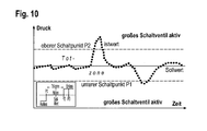
- FIG. 10 the basic principle of operation is graphically clarified again. If the controlled variable (actual state) goes beyond the limits marked by the switching points of the dead zone of the control, according to the prescribed switching characteristics, the switching valves 20, 22, 28 are activated to re-adjust the controlled variable of the reference variable (setpoint).
- FIG. 11 shows the characteristics of the current waveform that the output stage generates to allow the valves to rapidly switch.
- the programming (setting of bits in registers of the CJ840 electronic module) is performed manually, for example, via a computer. Different bit combinations in five registers stand for different properties, which are changeable. After switching on the power supply, the registers are set to a default setting.
- the current flow in FIG. 11 shows the current values resulting from the initial setting.
- the switch-on behavior of the switching valves 20, 22, 28 is essentially divided into five phases.
- the control signal of the control gives the command to open the switching valve 20, 22, 28 to the power amplifier on.
- a large current is first required, which is achieved via a voltage of 65 volts maximum.
- the current of this so-called boost phase is adjustable as well as the time frame available to the boost. The greater this power boost, the faster the magnetic field in a solenoid coil of the actuator 32 can FIG. 1 build up and set the valve armature in motion.
- the subsequent "pick-up" phase which occupies a certain current value via pulse width modulated voltage until the switching valve 20, 22, 28 has guaranteed opened.
- phase of the holding current control is used to maintain the open state and is also terminated by fast deletion when requested to close. Again, timeframes and current values are adjustable.
- volume flow pulsations can occur, which in turn can be a pulsation of the pressure.
- the controlled variable points through the
- Pulsation on a signal-noisy history For the most accurate and efficient control but the scanning of the most accurate control variable is necessary. For smoothing the sample size, there are various possibilities, which are explained below.
- the filtering of the signal can be implemented by means of a simple PT1 element.
- the corner frequency of the transmission f E is changed over the time constant T z .
- Another option for low-pass filtering is the compressibility and inertia of the hydraulic medium.
- the approach thus provides a smoothing or damping of the pulsation signal, which takes place before the measuring element in the transmission medium.
- the pulsation arrives correspondingly damped at the sensor.
- a numerical pulsation filter Another option for smoothing is provided by a numerical pulsation filter.
- the relevant disturbance factor in the controlled variable represents the pulsation. It is mainly dependent on the speed and the number of engine pistons. Therefore, the pulsation can be approximately mathematically described by a sine wave.
- the approach results from the pressure signal determined by the pressure transducer to effectively eliminate the pulsation.
- the pulsation does not represent an ideal sine, but a superimposition of several sine signals with different frequencies and amplitudes. Therefore, when filtering with a simplified sine, only the largest disturbances can be filtered out.
- all other sine signals in the filtering would have to be calculated with, as well as other influences. Among other things, influences on the characteristic of the pulsation result from the load behavior, which, however, is difficult to predict.
- FIG. 12 Another way to optimize the control is to change the switching frequency, see FIG. 12 .
- a greater reactivity of the control should be able to bring a higher switching frequency.
- the switching frequency can not be increased arbitrarily.
- the dynamics of the switching valves dictate the limits of the maximum possible switching frequency. This means that the maximum possible duty cycle within the cycle period must not be less than the switching behavior of the switching valve 20, 22, 28 allows it.
- the relative duty cycle at the switching frequency 200 Hz at one millisecond.
- the valve alone requires 0.6 ms for opening and closing, only 0.7 ms would be available for the open state and for the maximum on time.
- the reaction of the control is no longer dependent on a variable duty cycle, but on the sum of the switching operations with constant duty cycles of one millisecond.
- the only way to influence the duty cycle is to increase the sampling rate by two times.
- opening times are possible with half of the maximum duty cycle. Since the opening and closing times of the valve remain fixed, this results in a reduction of the dosing process by 0.2 ms. Therefore, the switching frequency of 200 Hz can be considered as the upper limit.
- the realization of larger switching frequencies would not be worthwhile because the switching dynamics of the solenoid valves could no longer meet the switching requirements.
- Another way to increase the reactivity could be the extension of the control by an internal feedback with adjustable time response. Like the control loop in FIG. 13 shows, this is realized via an internal feedback with a PT1 element.
- the control deviation is modified accordingly, so that the switching points of the three-point controller are reached earlier. Due to the returning correction, the control deviation becomes, as it were, an anticipatory character. As a result, the control causes the manipulated variable change earlier and can thus more quickly counteract a controlled variable deviating from the setpoint.
- the magnitude of the correction step results from the feedback quantities, the gain K r and the time constant T r and is proportional to the size of the input jump.
- the P component of the controller results from the manipulated variable change resulting from the correction step. Due to its integrative character in the control loop, the adjustment is part of the controller function (I component).
- the transfer function shows that this controller has a PI behavior.
- the overall gain of the quasi-PI controller becomes smaller. Due to the anticipatory character of the control deviation modified by the feedback, the switching points of the control are reached earlier.
- the inlet valve has by the larger volume flow that it can provide, so to speak, a greater reinforcing effect than the exhaust valve 28. Therefore, the outlet valve 28 should be allowed a lower advance, since the risk of overdosing due to the smaller volume flow amplification is lower than the inlet valve 20. A for each valve 20, 28 own feedback allows so individual configurations, which can meet the different volume flow gains.
- a sampling frequency of more than 2 kHz would not be worthwhile, since the valves 20, 22, 28 require at least 300 ⁇ s until they have opened or closed completely.
- a sampling time window of greater than the opening or closing time guarantees that the valve 20, 22 28 can not be interrupted during the opening or closing process. So it can be better ensured that the valve 20, 22, 28 is not unnecessarily often energized in vain.
- FIG. 14 a hydraulic circuit diagram is shown showing a displacement machine 38 which can be used as a hydraulic pump and motor.
- a further actuating cylinder 40 is shown, which has a piston 42. From the piston 42, a piston rod 44 which engages a swash plate, not shown, of the displacement machine 38 extends.
- the piston 42 defines with its side facing away from the piston rod 44 side a cylinder chamber 46 which is connected to the pressure line 14 of the displacement machine 38.
- a spring 48 is arranged, which acts on the piston 42 with a spring force in the direction of the increasing cylinder chamber 46.
- the piston 42 of the adjusting cylinder 40 acts against the piston 4 of the adjusting cylinder 2.
- FIG. 14 no second switching valve between the cylinder chamber 6 and the pressure line 14 and no overflow valve provided.
- the switching valves 20, 22 and 28 off FIG. 1 or the switching valves 20 and 28 off FIG. 14 can be controlled in Pulse Width Modulated mode (PWM), Meter In / Meter Out (MIO) or Ballistic Mode (BAM).
- PWM Pulse Width Modulated mode
- MIO Meter In / Meter Out
- BAM Ballistic Mode
- FIG. 1 in which two switching valves 20 and 22 are provided on the pressure medium flow path between the pressure line 14 and the cylinder chamber 6, the switching valves in the pulse code modulated mode (PCM) be controlled.
- PCM pulse code modulated mode
- the control of switching valves in ballistic mode for example, in the document DE 10 2009 052 285 A1 disclosed.
- an adjusting unit for an adjustable hydraulic displacement machine with a pressure-flow regulator has at least one actuating cylinder for adjusting a displacement of the positive displacement machine.
- the actuating cylinder is controlled via switching valves.
Landscapes
- Engineering & Computer Science (AREA)
- Mechanical Engineering (AREA)
- General Engineering & Computer Science (AREA)
- Physics & Mathematics (AREA)
- Fluid Mechanics (AREA)
- Fluid-Pressure Circuits (AREA)
- Control Of Fluid Pressure (AREA)
Applications Claiming Priority (1)
| Application Number | Priority Date | Filing Date | Title |
|---|---|---|---|
| DE102012009729A DE102012009729A1 (de) | 2012-05-15 | 2012-05-15 | Druck-Förderstromregler, Verstelleinheit für eine verstellbare hydraulische Verdrängermaschine mit einem Druck- Förderstromregler und Verfahren zum Regeln einer derartigen Verstelleinheit |
Publications (1)
| Publication Number | Publication Date |
|---|---|
| EP2664804A2 true EP2664804A2 (fr) | 2013-11-20 |
Family
ID=48190666
Family Applications (1)
| Application Number | Title | Priority Date | Filing Date |
|---|---|---|---|
| EP13002058.9A Withdrawn EP2664804A2 (fr) | 2012-05-15 | 2013-04-19 | Régulateur de pression et de débit, unité de réglage pour une machine de refoulement hydraulique réglable dotée d'un régulateur de pression et de débit et procédé de régulation d'une telle unité de réglage |
Country Status (3)
| Country | Link |
|---|---|
| EP (1) | EP2664804A2 (fr) |
| CN (1) | CN103423219A (fr) |
| DE (1) | DE102012009729A1 (fr) |
Cited By (7)
| Publication number | Priority date | Publication date | Assignee | Title |
|---|---|---|---|---|
| CN104533865A (zh) * | 2015-01-08 | 2015-04-22 | 中国人民解放军国防科学技术大学 | 一种液压节能控制器 |
| WO2016030260A1 (fr) * | 2014-08-28 | 2016-03-03 | Robert Bosch Gmbh | Circuit régulateur de pression |
| CN109654079A (zh) * | 2017-10-12 | 2019-04-19 | 华东交通大学 | 全开关阀组合的出口节流负载口独立控制阀 |
| WO2021204542A1 (fr) * | 2020-04-09 | 2021-10-14 | Rheinisch-Westfälische Technische Hochschule (Rwth) Aachen | Ensemble constitué d'un système de travail pour réaliser un travail à l'aide d'un fluide hydraulique sous pression et d'un dispositif de pompe |
| WO2022207416A1 (fr) * | 2021-03-30 | 2022-10-06 | Andreas Lupold Hydrotechnik Gmbh | Dispositif de régulation d'une pompe hydraulique ou d'un moteur hydraulique |
| CN116717516A (zh) * | 2022-03-07 | 2023-09-08 | 哈威液压股份公司 | 电液控制设备及可调液压泵系统 |
| CN119288928A (zh) * | 2024-09-14 | 2025-01-10 | 北京航空航天大学 | 基于均值自适应的溢流式流体脉动主动控制方法、装置及系统 |
Families Citing this family (6)
| Publication number | Priority date | Publication date | Assignee | Title |
|---|---|---|---|---|
| DE102017200537A1 (de) | 2017-01-13 | 2018-07-19 | Robert Bosch Gmbh | Verfahren und Steuereinrichtung zum Betrieb einer Hubkolbenpumpe |
| DE102018212042A1 (de) * | 2018-07-19 | 2020-01-23 | Robert Bosch Gmbh | Hydromaschine mit geregeltem Verdrängungsvolumen |
| DE102018132914A1 (de) * | 2018-12-19 | 2020-06-25 | Tkr Spezialwerkzeuge Gmbh | Hydraulikwerkzeug sowie Verfahren zur automatischen Steuerung von pneumatisch angetriebenen Hydraulikwerkzeugen |
| DE102019205505A1 (de) * | 2019-04-16 | 2020-10-22 | Robert Bosch Gmbh | Axialkolbenpumpe für einen hydrostatischen Fahrantrieb, hydrostatischer Fahrantrieb mit der Axialkolbenpumpe, sowie Verfahren zur Steuerung |
| DE102019216771A1 (de) * | 2019-10-30 | 2021-05-06 | Robert Bosch Gmbh | Hydraulische Steueranordnung zur Druckmittelversorgung wenigstens zweier hydraulischer Verbraucher |
| CN115899020B (zh) * | 2022-12-19 | 2023-07-21 | 东北林业大学 | 一种比例阀控缸动态特性测试可编程试验台 |
Citations (2)
| Publication number | Priority date | Publication date | Assignee | Title |
|---|---|---|---|---|
| DE102009052285A1 (de) | 2009-11-09 | 2011-05-12 | Robert Bosch Gmbh | Digitalhydraulik-Ventilstufe |
| DE102010048070A1 (de) | 2010-04-16 | 2011-10-20 | Robert Bosch Gmbh | Druck-Förderstromregler |
Family Cites Families (6)
| Publication number | Priority date | Publication date | Assignee | Title |
|---|---|---|---|---|
| DE10105712C1 (de) * | 2001-02-08 | 2002-06-06 | Wessel Hydraulik | Schaltungsanordnung zur Steuerung des hydraulischen Antriebs des Pressbalkens und des Messerbalkens einer Papierschneidemaschine |
| DE10210877A1 (de) * | 2002-03-12 | 2003-11-27 | Wabco Gmbh & Co Ohg | Ventileinrichtung für Stellzylinder |
| KR100641397B1 (ko) * | 2005-09-15 | 2006-11-01 | 볼보 컨스트럭션 이키프먼트 홀딩 스웨덴 에이비 | 유압제어시스템 |
| CN101410632B (zh) * | 2006-03-30 | 2013-02-13 | 油研工业株式会社 | 液压供给装置及采用该液压供给装置的液压促动装置的控制方法 |
| DE102006023798B3 (de) * | 2006-05-20 | 2008-01-31 | Wessel-Hydraulik Gmbh | Vorrichtung zur Steuerung einer Papierschneidemaschine |
| CN201100473Y (zh) * | 2007-11-16 | 2008-08-13 | 池双 | 弹簧蓄能式电液联动阀门执行器 |
-
2012
- 2012-05-15 DE DE102012009729A patent/DE102012009729A1/de not_active Withdrawn
-
2013
- 2013-04-19 EP EP13002058.9A patent/EP2664804A2/fr not_active Withdrawn
- 2013-05-14 CN CN2013101766009A patent/CN103423219A/zh active Pending
Patent Citations (2)
| Publication number | Priority date | Publication date | Assignee | Title |
|---|---|---|---|---|
| DE102009052285A1 (de) | 2009-11-09 | 2011-05-12 | Robert Bosch Gmbh | Digitalhydraulik-Ventilstufe |
| DE102010048070A1 (de) | 2010-04-16 | 2011-10-20 | Robert Bosch Gmbh | Druck-Förderstromregler |
Cited By (9)
| Publication number | Priority date | Publication date | Assignee | Title |
|---|---|---|---|---|
| WO2016030260A1 (fr) * | 2014-08-28 | 2016-03-03 | Robert Bosch Gmbh | Circuit régulateur de pression |
| CN104533865A (zh) * | 2015-01-08 | 2015-04-22 | 中国人民解放军国防科学技术大学 | 一种液压节能控制器 |
| CN109654079A (zh) * | 2017-10-12 | 2019-04-19 | 华东交通大学 | 全开关阀组合的出口节流负载口独立控制阀 |
| CN109654079B (zh) * | 2017-10-12 | 2024-02-20 | 华东交通大学 | 全开关阀组合的出口节流负载口独立控制阀 |
| WO2021204542A1 (fr) * | 2020-04-09 | 2021-10-14 | Rheinisch-Westfälische Technische Hochschule (Rwth) Aachen | Ensemble constitué d'un système de travail pour réaliser un travail à l'aide d'un fluide hydraulique sous pression et d'un dispositif de pompe |
| WO2022207416A1 (fr) * | 2021-03-30 | 2022-10-06 | Andreas Lupold Hydrotechnik Gmbh | Dispositif de régulation d'une pompe hydraulique ou d'un moteur hydraulique |
| CN116234983A (zh) * | 2021-03-30 | 2023-06-06 | 安德烈亚斯卢波德水电技术有限公司 | 用于控制压泵或液压马达的装置 |
| CN116717516A (zh) * | 2022-03-07 | 2023-09-08 | 哈威液压股份公司 | 电液控制设备及可调液压泵系统 |
| CN119288928A (zh) * | 2024-09-14 | 2025-01-10 | 北京航空航天大学 | 基于均值自适应的溢流式流体脉动主动控制方法、装置及系统 |
Also Published As
| Publication number | Publication date |
|---|---|
| CN103423219A (zh) | 2013-12-04 |
| DE102012009729A1 (de) | 2013-11-21 |
Similar Documents
| Publication | Publication Date | Title |
|---|---|---|
| EP2664804A2 (fr) | Régulateur de pression et de débit, unité de réglage pour une machine de refoulement hydraulique réglable dotée d'un régulateur de pression et de débit et procédé de régulation d'une telle unité de réglage | |
| EP2014919B1 (fr) | Soupape de réglage pour le réglage du volume d'alimentation d'une pompe volumétrique | |
| EP2449242B1 (fr) | Méthode de contrôle et de régulation de la pression du carburant d'un rail commun d'un moteur à combustion | |
| EP2602492A2 (fr) | Dispositif de commande électro-hydraulique | |
| DE102007007005A1 (de) | Elektrohydraulische Steueranordnung | |
| EP3748168B1 (fr) | Système d'entraînement hydraulique à deux pompes et à récupération d'énergie | |
| DE4228599B4 (de) | Hydraulikkreis für die Versorgung mehrerer, seriell betriebener Verbraucher einer hydraulisch gesteuerten Anlage | |
| EP0856107A1 (fr) | Regulation de puissance avec detection de charge | |
| EP3770431A1 (fr) | Agencement et procédé d'alimentation en moyen de pression hydraulique | |
| EP3874338B1 (fr) | Procédé de fonctionnement d'une soupape, unité de commande électronique associée et entraînement de soupape | |
| DE102019110710B3 (de) | Ansteuerverfahren für ein Hydrauliksystem mit einer Pumpe und mehreren Ventilen; sowie Hydrauliksystem | |
| WO2002002974A2 (fr) | Unite soupape de commande pour un ascenseur hydraulique | |
| EP4081871B1 (fr) | Procédé de commande d'un système partiellement électronique | |
| DE10308289B4 (de) | LS-Wegeventilblock | |
| EP2615278B1 (fr) | Dispositif de dosage avec mélangeur de gaz et procédé de commande de la formation de mélange | |
| DE102005050216A1 (de) | Volumenstromgeregelte, einhubige Flügelzellenpumpe | |
| EP2824334A1 (fr) | Entraînement linéaire hydraulique | |
| DE3311351A1 (de) | Regeleinrichtung fuer die kraftstoffzumessung bei einer dieselbrennkraftmaschine | |
| DE10134747B4 (de) | Verfahren und Vorrichtung zur lastabhängigen Steuerung der Fluidversorgung eines Fluidkreises | |
| WO2009053145A1 (fr) | Structure de régulateur pour unité de vérin hydraulique avec régulateur d'état sous-jacent | |
| DE4136813C2 (de) | Arbeitsflüssigkeits-Kreislauf für einen Regelkreis einer aktiven Radaufhängung eines Fahrzeugs | |
| DE3329347C2 (de) | Elektro-hydraulische Betätigungsvorrichtung für ein stetig verstellbares Ventil | |
| DE102009030165A1 (de) | Ein AntiWindup-Konzept zur besseren Kombination eines Reglers mit einer Steuerung | |
| EP2836879B1 (fr) | Dispositif de régulation pour une unité de cylindre hydraulique avec commande séparée de chaque soupape | |
| WO2000052337A1 (fr) | Dispositif et procede permettant de regler un compresseur par etranglement du courant fluidique d'admission |
Legal Events
| Date | Code | Title | Description |
|---|---|---|---|
| PUAI | Public reference made under article 153(3) epc to a published international application that has entered the european phase |
Free format text: ORIGINAL CODE: 0009012 |
|
| AK | Designated contracting states |
Kind code of ref document: A2 Designated state(s): AL AT BE BG CH CY CZ DE DK EE ES FI FR GB GR HR HU IE IS IT LI LT LU LV MC MK MT NL NO PL PT RO RS SE SI SK SM TR |
|
| AX | Request for extension of the european patent |
Extension state: BA ME |
|
| STAA | Information on the status of an ep patent application or granted ep patent |
Free format text: STATUS: THE APPLICATION IS DEEMED TO BE WITHDRAWN |
|
| 18D | Application deemed to be withdrawn |
Effective date: 20171103 |