EP2665060B1 - Gerät zur kodierung eines sprach-/tonsignal - Google Patents
Gerät zur kodierung eines sprach-/tonsignal Download PDFInfo
- Publication number
- EP2665060B1 EP2665060B1 EP11855814.7A EP11855814A EP2665060B1 EP 2665060 B1 EP2665060 B1 EP 2665060B1 EP 11855814 A EP11855814 A EP 11855814A EP 2665060 B1 EP2665060 B1 EP 2665060B1
- Authority
- EP
- European Patent Office
- Prior art keywords
- section
- auto
- correlation
- subframe
- energy
- Prior art date
- Legal status (The legal status is an assumption and is not a legal conclusion. Google has not performed a legal analysis and makes no representation as to the accuracy of the status listed.)
- Not-in-force
Links
- 230000005236 sound signal Effects 0.000 title claims description 16
- 238000004364 calculation method Methods 0.000 claims description 68
- 238000001914 filtration Methods 0.000 claims description 19
- 238000004891 communication Methods 0.000 claims description 10
- 239000011159 matrix material Substances 0.000 description 72
- 230000005284 excitation Effects 0.000 description 70
- 238000012545 processing Methods 0.000 description 58
- 238000000034 method Methods 0.000 description 40
- 238000013139 quantization Methods 0.000 description 33
- 239000013598 vector Substances 0.000 description 32
- 230000003044 adaptive effect Effects 0.000 description 30
- 238000010586 diagram Methods 0.000 description 24
- 230000015572 biosynthetic process Effects 0.000 description 14
- 238000003786 synthesis reaction Methods 0.000 description 14
- 238000004458 analytical method Methods 0.000 description 12
- 238000007781 pre-processing Methods 0.000 description 12
- 238000012805 post-processing Methods 0.000 description 11
- 230000006866 deterioration Effects 0.000 description 10
- 230000000875 corresponding effect Effects 0.000 description 8
- 230000005540 biological transmission Effects 0.000 description 7
- 230000008569 process Effects 0.000 description 6
- 238000003860 storage Methods 0.000 description 6
- 238000005516 engineering process Methods 0.000 description 4
- 238000006467 substitution reaction Methods 0.000 description 4
- 230000010354 integration Effects 0.000 description 3
- 238000013507 mapping Methods 0.000 description 3
- 230000015556 catabolic process Effects 0.000 description 2
- 230000002596 correlated effect Effects 0.000 description 2
- 238000006731 degradation reaction Methods 0.000 description 2
- 230000000694 effects Effects 0.000 description 2
- 239000000284 extract Substances 0.000 description 2
- 230000006870 function Effects 0.000 description 2
- 238000010295 mobile communication Methods 0.000 description 2
- 230000004044 response Effects 0.000 description 2
- 230000001052 transient effect Effects 0.000 description 2
- 230000008901 benefit Effects 0.000 description 1
- 150000001875 compounds Chemical class 0.000 description 1
- 230000006835 compression Effects 0.000 description 1
- 238000007906 compression Methods 0.000 description 1
- 230000001276 controlling effect Effects 0.000 description 1
- 230000005484 gravity Effects 0.000 description 1
- 238000004519 manufacturing process Methods 0.000 description 1
- 239000000203 mixture Substances 0.000 description 1
- 239000004065 semiconductor Substances 0.000 description 1
- 238000007493 shaping process Methods 0.000 description 1
- 230000007480 spreading Effects 0.000 description 1
- 238000003892 spreading Methods 0.000 description 1
- 230000003068 static effect Effects 0.000 description 1
- 239000002699 waste material Substances 0.000 description 1
Images






Classifications
-
- G—PHYSICS
- G10—MUSICAL INSTRUMENTS; ACOUSTICS
- G10L—SPEECH ANALYSIS TECHNIQUES OR SPEECH SYNTHESIS; SPEECH RECOGNITION; SPEECH OR VOICE PROCESSING TECHNIQUES; SPEECH OR AUDIO CODING OR DECODING
- G10L19/00—Speech or audio signals analysis-synthesis techniques for redundancy reduction, e.g. in vocoders; Coding or decoding of speech or audio signals, using source filter models or psychoacoustic analysis
- G10L19/04—Speech or audio signals analysis-synthesis techniques for redundancy reduction, e.g. in vocoders; Coding or decoding of speech or audio signals, using source filter models or psychoacoustic analysis using predictive techniques
- G10L19/08—Determination or coding of the excitation function; Determination or coding of the long-term prediction parameters
- G10L19/12—Determination or coding of the excitation function; Determination or coding of the long-term prediction parameters the excitation function being a code excitation, e.g. in code excited linear prediction [CELP] vocoders
-
- G—PHYSICS
- G10—MUSICAL INSTRUMENTS; ACOUSTICS
- G10L—SPEECH ANALYSIS TECHNIQUES OR SPEECH SYNTHESIS; SPEECH RECOGNITION; SPEECH OR VOICE PROCESSING TECHNIQUES; SPEECH OR AUDIO CODING OR DECODING
- G10L19/00—Speech or audio signals analysis-synthesis techniques for redundancy reduction, e.g. in vocoders; Coding or decoding of speech or audio signals, using source filter models or psychoacoustic analysis
-
- G—PHYSICS
- G10—MUSICAL INSTRUMENTS; ACOUSTICS
- G10L—SPEECH ANALYSIS TECHNIQUES OR SPEECH SYNTHESIS; SPEECH RECOGNITION; SPEECH OR VOICE PROCESSING TECHNIQUES; SPEECH OR AUDIO CODING OR DECODING
- G10L25/00—Speech or voice analysis techniques not restricted to a single one of groups G10L15/00 - G10L21/00
- G10L25/03—Speech or voice analysis techniques not restricted to a single one of groups G10L15/00 - G10L21/00 characterised by the type of extracted parameters
- G10L25/06—Speech or voice analysis techniques not restricted to a single one of groups G10L15/00 - G10L21/00 characterised by the type of extracted parameters the extracted parameters being correlation coefficients
-
- G—PHYSICS
- G10—MUSICAL INSTRUMENTS; ACOUSTICS
- G10L—SPEECH ANALYSIS TECHNIQUES OR SPEECH SYNTHESIS; SPEECH RECOGNITION; SPEECH OR VOICE PROCESSING TECHNIQUES; SPEECH OR AUDIO CODING OR DECODING
- G10L25/00—Speech or voice analysis techniques not restricted to a single one of groups G10L15/00 - G10L21/00
- G10L25/03—Speech or voice analysis techniques not restricted to a single one of groups G10L15/00 - G10L21/00 characterised by the type of extracted parameters
- G10L25/21—Speech or voice analysis techniques not restricted to a single one of groups G10L15/00 - G10L21/00 characterised by the type of extracted parameters the extracted parameters being power information
Definitions
- the present invention relates to a coding apparatus used for a communication system that encodes and transmits a signal.
- Compression coding techniques are often used when transmitting a speech/sound signal in a packet communication system represented by Internet communication or a mobile communication system or the like, to improve transmission efficiency of the speech/sound signal.
- a technique for encoding a wider band speech/sound signal and a technique for encoding/decoding with a low amount of processing calculation without causing d egradation of sound quality.
- Linear Prediction type coding apparatus calculates energy of an inputted speech signal before a linear predictive analysis.
- a linear predictive analysis is performed only when the calculated energy is determined not to be 0, whereas a linear prediction coefficient according to a predetermined fixed pattern is outputted when the calculated energy is determined to be 0.
- This scheme can cut down on waste of performing a time-consuming linear predictive analysis and thereby shorten the processing time and also suppress current consumption accompanying the amount of processing calculation.
- WO 02/099787 A1 describes methods and apparatus for quickly selecting an optimal excitation waveform from a codebook which are presented herein.
- storage and processor load is reduced by approximating a two-dimensional autocorrelation matrix with a one-dimensional autocorrelation vector.
- the approximation is possible when a cross-correlation element is configured to determine the autocorrelation matrix of an impulse response and a pulse energy determination element is configured to determine the energy of a pulse code vector that incorporates secondary pulse positions.
- WO 02/099788 A1 further describes methods and apparatus for quickly selecting an optimal excitation waveform from a codebook which are presented herein.
- a subset of codevectors are selected based upon optimal pulse locations (425), wherein the subset of codevectors form a subcodebook. Rather than searching the entire codebook, only the entries of the subcodebook are searched (400).
- US 5 717 825 A specifies an Algebraic code-excited linear prediction speech coding method which uses the technique of CELP coding with algebraic codebook.
- the memory-stored components of the covariance matrix are only those of the form U(pos i,p , pos i,p ) and those of the form U(pos i,p , pos j,q ), pos i,p and pos j,q respectively denoting position i and position for the pulses p and q in the codes of the algebraic codebook.
- US 5 924 062 A specifies an ACLEP codec with modified autocorrelation matrix storage and search whereby a codebook correlation matrix comprises a Toeplitz-type (diagonally symmetric) matrix which is calculated from a forty sample subframe of a speech signal, forming a 40x40 matrix.
- the resulting correlation coefficients which constitute the codes are stored within a DSP's local memory after calculation by dividing the matrix into five predefined x- and y- tracks, each track having a unique set of eight pulse positions. Using the eight pulse positions on each track, fifteen 8x8 sub-matrices are created which include all of the correlation coefficients in the original 40x40 matrix.
- the sub-matrices are distributed within a 5x5 mapping matrix which is correlated with a structure mapping matrix to determine the configuration of the resulting autocorrelation matrix for storage and searching.
- the sub-matrices within each column of correlated mapping matrices are searched by directing a multiplex pointer to that particular column.
- the coding apparatus first applies pre-processing such as removal of a DC component and removal of a low-frequency region to the inputted speech signal (hereinafter, referred to as "input signal").
- the coding apparatus calculates an auto-correlation of the input signal subjected to the pre-processing and calculates average frame energy (calculates ⁇ (0, 0) and ⁇ (10, 10) in the above-described Patent Literature) using this auto-correlation.
- PTL 1 then discloses a configuration of determining whether or not the above-described average frame energy is 0 and omitting subsequent linear predictive analysis processing when the average frame energy is 0.
- performing approximate auto-correlation operations makes it possible to drastically reduce the amount of processing calculation (amount of calculation) without causing deterioration of the accuracy of frame energy or subframe energy.
- An input signal which will be used hereinafter is a generic term for a signal obtained by converting so-called sound to an electric signal such as speech signal, audio signal or a mixture of these signals.
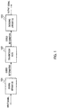
- FIG. 1 is a block diagram illustrating a configuration of a communication system including a coding apparatus and a decoding apparatus according to an embodiment of the present invention.
- the communication system is provided with coding apparatus 101 and decoding apparatus 103, which are communicable with each other via transmission path 102. Both of coding apparatus 101 and decoding apparatus 103 are used while being normally mounted on a base station apparatus or communication terminal apparatus or the like.
- the present embodiment will describe a configuration in which subsequent linear predictive analysis processing is omitted when subframe energy (frame energy) is 0.
- the present embodiment is different from PTL 1 in a method of calculating subframe energy (frame energy).
- Coding apparatus 101 divides an input signal into blocks of N samples (N is a natural number) each and encodes the input signal in frame units, with one frame being composed of N samples.
- N is a natural number
- Symbol n represents an (n+1)-th signal element of the input signal divided into blocks of N samples.
- Coding apparatus 101 transmits encoded input information (encoded information) to decoding apparatus 103 via transmission path 102.
- Decoding apparatus 103 receives the encoded information transmitted from coding apparatus 101 via transmission path 102, decodes the encoded information and obtains an output signal.
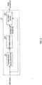
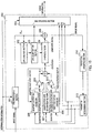
- FIG. 2 is a block diagram illustrating an internal configuration of coding apparatus 101 shown in FIG. 1 .
- Coding apparatus 101 is mainly constructed of subframe energy calculation section 201, determining section 202, and CELP coding section 203. It is assumed that subframe energy calculation section 201, determining section 202 and CELP coding section 203 perform processing in subframe units. Hereinafter, details of each process will be described.
- the above setting example is merely an example, and the present invention is similarly applicable to cases where determining section 202 sets the value to another value.
- CELP coding section 203 encodes the input signal using the inputted determination information. Details of the coding processing in CELP coding section 203 will be described later.
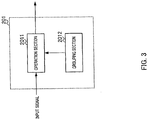
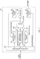
- FIG. 3 is a diagram illustrating the internal configuration of subframe energy calculation section 201.
- Subframe energy calculation section 201 includes grouping section 2012, and operation section 2011.
- a configuration will be described in the present embodiment as an example where operation section 2011 of subframe energy calculation section 201 collectively performs filtering processing and auto-correlation calculation on the input signal.
- Grouping section 2012 is assumed to have information of order P of a filter coefficient beforehand. Grouping section 2012 then groups elements of an auto-correlation matrix into a plurality of groups according to variables j and m and outputs the grouping information to operation section 2011. The grouping method in grouping section 2012 will be described later.
- Operation section 2011 calculates subframe energy based on the grouping information. In that case, operation section 2011 collectively performs filtering processing and auto-correlation calculation processing on the input signal. The method of calculating subframe energy in operation section 2011 will be described later.
- start k and end k indicate a leading sample index and a tail-end sample index, respectively, of a subframe whose subframe index is k.
- subframe energy calculation section 201 simply performs filtering processing on an input signal and calculates auto-correlation on the input signal after filtering.
- the order of the filter coefficient at this time is P.
- Equation 3 shows filtering processing on input signal x n .
- the filtering processing here is not limited to filter types such as low pass filter, high pass filter and band pass filter.
- subframe energy calculation section 201 calculates P-th order auto-correlation ⁇ (j, m) on input signal A i after filtering obtained from equation 3.
- subframe energy calculation section 201 obtains subframe energy E k of input signal A i subjected to filtering processing using a covariance according to equation 4 below.
- Accurate subband energy can be calculated according to equation 4 above.
- the respective auto-correlations need to be calculated in accordance with the values of j and m, which results in a problem that the amount of calculation becomes enormous.
- subframe energy calculation section 201 of the present invention simplifies the operation in equation 4 above without causing deterioration of the accuracy, and thereby drastically reduces the amount of calculation.
- the present invention does not actually perform filtering processing on the input signal, but performs processing substantially equivalent to processing of calculating frame energy (subframe energy) of the input signal subjected to filtering processing, that is, approximate calculation processing. For this reason, suppose that coefficients of filtering processing are used. That is, according to the present invention, the filtering processing itself in the above simple configuration is also included in the method of calculating frame energy (subframe energy) which will be described later.
- the present invention is likewise applicable to various types of filter processing.
- the method of calculating subframe energy in subframe energy calculation section 201 of the present invention will be described in detail below.
- Equation 4 above can be modified as equation 5 below.
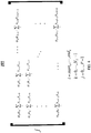
- equation 5 can be expressed as the sum of elements of a matrix in FIG. 4 (matrix elements).
- S ⁇ 1 ⁇ 0 ⁇ 0 ⁇ i x i i + ⁇ 0 ⁇ 1 ⁇ i x i x i ⁇ 1 + ⁇ + ⁇ ⁇ 0 ⁇ P ⁇ 1 ⁇ i x i i ⁇ P ⁇ 1 + ⁇ 1 ⁇ 0 ⁇ i x i ⁇ 1 x i + ⁇ 1
- the portion of filter coefficient ⁇ j ⁇ m of each term is independent of i and ⁇ j ⁇ m is a predetermined filter coefficient, and therefore ⁇ j ⁇ m need not be calculated for each frame process. Therefore, the portion that needs to be calculated for each frame process is the portion of ⁇ x i-j x i-m of each term in equation 5 and this portion needs to be calculated for each of i, j and m.
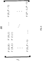
- the calculation expression of the portion of Ex i-j x i-m only can be expressed as the sum of a matrix in FIG. 5 (hereinafter, referred to as "auto-correlation matrix").
- the auto-correlation matrix in FIG. 5 has a format in which filter coefficient ⁇ j ⁇ m is omitted from the matrix in FIG. 4 .
- the value of the auto-correlation remains the same even if the values of j and m are switched around, and therefore the values of the respective elements can be expressed as equation 6 below in accordance with the combination of values of j and m.
- the auto-correlation matrix in FIG. 5 can be further simplified as shown in FIG. 6 .
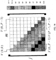
- FIG. 7 is a conceptual configuration diagram of the auto-correlation matrix in FIG. 6 . It is assumed that each region in FIG. 7 indicates each element (matrix element) (V(j, m)) in FIG. 6 . Furthermore, since the regions enclosed by a broken line in the upper right area of the matrix correspond to the regions at the lower left area (shaded area) of the matrix respectively, the calculation of the auto-correlation can be actually omitted.
- FIG. 7 only shows the concept of the configuration of the auto-correlation matrix, an example of case where order P of the filter coefficient is 10, and the number of regions (matrix elements), that is, the order of the filter coefficient is not limited to this.
- subframe energy calculation section 201 of the present invention simplifies the auto-correlation matrix as shown in FIG. 8 (hereinafter, referred to as "simplified auto-correlation matrix").
- grouping section 2012 of subframe energy calculation section 201 groups the elements of the auto-correlation matrix into a plurality of groups in accordance with variables j and m.
- the simplified auto-correlation matrix in FIG. 8 is a simplified version of the conceptual configuration diagram of the auto-correlation matrix shown in FIG. 7 .
- FIG. 8 is an example where grouping section 2012 groups the respective elements of the auto-correlation matrix in accordance with variables j and m.
- grouping section 2012 sets a greater group region (hereinafter, referred to as "group region").
- FIG. 9 is a diagram showing the correspondence between the difference between variables j and m, and each group. In FIG. 9 , number 0 to 9 shown in each region indicates the difference between variables j and m.
- the respective elements whose difference between variables j and m is 0 or 1 are grouped into groups G1 to G4, with each group being composed of 5 elements.
- the respective elements whose difference between variables j and m is 2 or 3 are grouped into groups G5 to G7, with each group being composed of 5 elements. Furthermore, the respective elements whose difference between variables j and m is 4 or 5 are grouped into groups G8 and G9, with each group being composed of 6 elements. Furthermore, 10 elements whose difference between variables j and m is 6, 7, 8 or 9 are grouped into group G10. That is, in the example in FIG. 8 , elements having a greater difference in values between variables j and m are grouped into a configuration in which auto-correlation values are more simplified (approximated).
- the simplified auto-correlation matrix is created based on an idea that the greater the difference between variables j and m, the coarser (more simplified) resolution of each value of the auto-correlation matrix is set.
- Grouping section 2012 outputs grouping information to operation section 2011.
- Operation section 2011 then calculates auto-correlation values assuming that all elements belonging to the same group have the same auto-correlation value. At this time, as the auto-correlation value in the same group, operation section 2011 sets, for example, an auto-correlation value of an element having the minimum sum of j and m in the group.
- Operation section 2011 of subframe energy calculation section 201 calculates auto-correlation corresponding to each symbol according to equation 6 based on the simplified auto-correlation matrix in FIG. 8 and calculates subframe energy according to equation 5 using the calculated value.
- grouping section 2012 of subframe energy calculation section 201 groups the respective elements of the auto-correlation matrix into a plurality of groups.
- the respective elements of the auto-correlation matrix are grouped into 10 groups G1 to G10.
- Subframe energy calculation section 201 sets, for example, an auto-correlation value of an element having the minimum sum of j and m in each group as an auto-correlation value of all elements included in the group.
- the present invention approximates (substitutes) the sum ( ⁇ x i-j x i-m ) of auto-correlation operations within a certain range (i, j) of an input signal that must be calculated when calculating accurate frame energy (subframe energy) with the sum ( ⁇ x i-j' x i-m' ) of auto-correlation operations within another range (i', j').
- a certain range i, j
- the present invention approximates (substitutes) the sum ( ⁇ x i-j x i-m ) of auto-correlation operations within a certain range (i, j) of an input signal that must be calculated when calculating accurate frame energy (subframe energy) with the sum ( ⁇ x i-j' x i-m' ) of auto-correlation operations within another range (i', j').
- the frequency of approximation (substitution) in accordance with a delay time (time difference between signals whose correlation is calculated) during auto-correlation operation, it is possible to suppress deterioration of the accuracy of frame energy (subframe energy) calculation.
- the delay time during auto-correlation operation increases, that is, as the difference between variables j and m in equation 5 increases, the frequency of approximation is increased, and it is thereby possible to suppress deterioration of the accuracy in energy calculation. That is, the greater the delay time during auto-correlation operation, that is, the greater the difference between variables j and m in equation 5, the greater group region is set by grouping section 2012.
- grouping section 2012 performs control so as to increase the frequency of substitution with the sum of auto-correlation operations in the identical second range as the delay time (difference between variables j and m) during auto-correlation operation increases.
- the delay time (difference between variables j and m) during auto-correlation operation is large, the frequency with which the sum ( ⁇ x i-j x i-m ) of auto-correlation operations within a certain range (i, j) of an input signal is approximated with the sum ( ⁇ x i-j' x i-m' ) of auto-correlation operation within another range (i', j') increases, and it is thereby possible to reduce the amount of calculation of auto-correlation.
- FIG. 10 is a block diagram illustrating a principal internal configuration of CELP coding section 203.
- CELP coding section 203 includes pre-processing section 301, LPC (Linear Prediction Coefficients) analysis section 302, LPC quantization section 303, synthesis filter 304, adding section 305, adaptive excitation codebook 306, quantization gain generation section 307, fixed excitation codebook 308, multiplying sections 309 and 310, adding section 311, perceptual weighting section 312, parameter determining section 313, and multiplexing section 314.
- LPC Linear Prediction Coefficients
- Determination information outputted from determining section 202 is inputted to pre-processing section 301.
- LPC analysis section 302 performs linear predictive analysis using signal X in inputted from pre-processing section 301 and outputs the analysis result (linear prediction coefficient) to LPC quantization section 303.
- LPC quantization section 303 performs quantization processing on the linear prediction coefficient (LPC) inputted from LPC analysis section 302, outputs the quantized LPC to synthesis filter 304 and outputs a code (L) representing the quantized LPC to multiplexing section 314.
- LPC linear prediction coefficient
- Synthesis filter 304 performs a filter synthesis on excitation inputted from adding section 311 which will be described later using a filter coefficient based on the quantized LPC inputted from LPC quantization section 303, generates a synthesized signal and outputs the synthesized signal to adding section 305.
- Adding section 305 inverts the polarity of the synthesized signal inputted from synthesis filter 304, adds the synthesized signal with the inverted polarity to signal X in inputted from pre-processing section 301, thereby calculates an error signal and outputs the error signal to perceptual weighting section 312.
- Adaptive excitation codebook 306 stores excitation outputted in the past from adding section 311 in a buffer, extracts samples corresponding to one frame from the past excitation specified by the signal inputted from parameter determining section 313 which will be described later, as an adaptive excitation vector, and outputs the samples to multiplying section 309.
- Quantization gain generation section 307 outputs a quantization adaptive excitation gain and a quantization fixed excitation gain specified by the signal inputted from parameter determining section 313 to multiplying section 309 and multiplying section 310 respectively.
- Fixed excitation codebook 308 outputs a pulse excitation vector having a shape specified by a signal inputted from parameter determining section 313 to multiplying section 310 as a fixed excitation vector.
- a vector obtained by multiplying the pulse excitation vector by a spreading vector may also be outputted to multiplying section 310 as the fixed excitation vector.
- Multiplying section 309 multiplies the adaptive excitation vector inputted from adaptive excitation codebook 306 by the quantization adaptive excitation gain inputted from quantization gain generation section 307 and outputs the multiplication result to adding section 311. Furthermore, multiplying section 310 multiplies the fixed excitation vector inputted from fixed excitation codebook 308 by the quantization fixed excitation gain inputted from quantization gain generation section 307 and outputs the multiplication result to adding section 311.
- Adding section 311 performs vector addition on the adaptive excitation vector multiplied by the gain inputted from multiplying section 309 and the fixed excitation vector multiplied by the gain inputted from multiplying section 310 and outputs excitation, which is the addition result, to synthesis filter 304 and adaptive excitation codebook 306.
- the excitation outputted to adaptive excitation codebook 306 is stored in the buffer of adaptive excitation codebook 306.
- Perceptual weighting section 312 performs perceptual weighting on the error signal inputted from adding section 305 and outputs the error signal to parameter determining section 313 as coding distortion.
- Parameter determining section 313 selects an adaptive excitation vector, fixed excitation vector and quantization gain that minimize the coding distortion inputted from perceptual weighting section 312 from adaptive excitation codebook 306, fixed excitation codebook 308 and quantization gain generation section 307 respectively, and outputs an adaptive excitation vector code (A), fixed excitation vector code (F) and quantization gain code (G) showing the selection results to multiplexing section 314.
- A adaptive excitation vector code
- F fixed excitation vector code
- G quantization gain code
- Determination information is inputted to multiplexing section 314 from determining section 202.
- CELP coding section 203 The processing in CELP coding section 203 has been described so far.
- decoding apparatus 103 shown in FIG. 1 will be described with reference to FIG. 11 .
- decoding section 103 performs CELP type speech decoding
- FIG. 11 is a block diagram illustrating a principal internal configuration of decoding apparatus 103.
- Decoding apparatus 103 includes demultiplexing section 401, LPC decoding section 402, adaptive excitation codebook 403, quantization gain generation section 404, fixed excitation codebook 405, multiplying sections 406 and 407, adding section 408, synthesis filter 409, and post-processing section 410.
- demultiplexing section 401 demultiplexes the encoded information inputted from coding apparatus 101 into individual codes (L), (A), (G), (F), and determination information.
- the demultiplexed LPC code (L) is outputted to LPC decoding section 402.
- the demultiplexed adaptive excitation vector code (A) is outputted to adaptive excitation codebook 403.
- the demultiplexed quantization gain code (G) is outputted to quantization gain generation section 404.
- the demultiplexed fixed excitation vector code (F) is outputted to fixed excitation codebook 405.
- the demultiplexed determination information is outputted to post-processing section 410.
- LPC decoding section 402 decodes the quantized LPC from the code (L) inputted from demultiplexing section 401 and outputs the decoded quantized LPC to synthesis filter 409.
- Adaptive excitation codebook 403 extracts samples corresponding to one frame from past excitation specified by the adaptive excitation vector code (A) inputted from demultiplexing section 401 as adaptive excitation vectors and outputs the samples to multiplying section 406.
- Quantization gain generation section 404 decodes the quantization adaptive excitation gain and the quantization fixed excitation gain specified by the quantization gain code (G) inputted from demultiplexing section 401, outputs the quantization adaptive excitation gain to multiplying section 406 and outputs the quantization fixed excitation gain to multiplying section 407.
- G quantization gain code
- Fixed excitation codebook 405 generates a fixed excitation vector specified by the fixed excitation vector code (F) inputted from demultiplexing section 401 and outputs the fixed excitation vector to multiplying section 407.
- Multiplying section 406 multiplies the adaptive excitation vector inputted from adaptive excitation codebook 403 by the quantization adaptive excitation gain inputted from quantization gain generation section 404 and outputs the multiplication result to adding section 408.
- multiplying section 407 multiplies the fixed excitation vector inputted from fixed excitation codebook 405 by the quantization fixed excitation gain inputted from quantization gain generation section 404 and outputs the multiplication result to adding section 408.
- Adding section 408 adds up the adaptive excitation vector multiplied by the gain inputted from multiplying section 406 and the fixed excitation vector multiplied by the gain inputted from multiplying section 407, generates excitation and outputs the excitation to synthesis filter 409 and adaptive excitation codebook 403.
- Synthesis filter 409 performs a filter synthesis of the excitation inputted from adding section 408 using the filter coefficient decoded by LPC decoding section 402 and outputs the synthesized signal to post-processing section 410.
- a storage apparatus provided in post-processing section 410 is caused to store an output signal of the current frame.
- post-processing section 410 multiplies the output signal in the past frame stored in the storage apparatus in post-processing section 410 by a predetermined coefficient (0 ⁇ 1.0) and outputs the multiplied signal as an output signal. Furthermore, the storage apparatus is caused to store the output signal at this time.
- Embodiment 1 of the present invention has been described so far.
- grouping section 2012 groups respective elements of an auto-correlation matrix into a plurality of groups in accordance with a delay time (that is, difference between j and m) during auto-correlation operation. For example, the greater the delay time (that is, difference between j and m) during auto-correlation operation, the more elements of the auto-correlation matrix are grouped into the same group by grouping section 2012.
- operation section 2011 sets the input signal after filtering as A i (see equation 3) and sets the sum ( ⁇ x i-j x i-m ) of auto-correlation operations in a first range (j, m) of this input signal A i as the sum ( ⁇ x i-j' x i-m' ) of auto-correlation operations in a second range (j', m') in the same group as the first range.
- grouping section 2012 increases the frequency of substitution with the sum of auto-correlation operations in the same second range (j', m'). That is, as the difference between j and m in equation 5 increases, grouping section 2012 increases the number of combinations of j and m to be substituted by auto-correlation operations at j' and m'. Thus, instead of simply using an average value, it is possible to approximate the auto-correlation operations in the first range, and thereby reduce the amount of calculation without causing deterioration of the calculation accuracy.
- FIG. 8 although the values of auto-correlation operation corresponding to regions having different j (or m) values are set to be the same, a method not falling under the defintion of the invention is also effective whereby grouping section 2012 of subframe energy calculation section 201 groups regions where differences between j and m are equal like a Toeplitz matrix.
- FIG. 12 shows this configuration example.
- group G1 is a group where the difference between j and m corresponds to 0.
- groups G2 to 10 are groups where the difference between j and m corresponds to 1 to 9, respectively.
- FIG. 13 shows an example of subframe energy calculation section 201a in this case.
- the difference from subframe energy calculation section 201 in FIG. 3 lies in that grouping section 2012a that receives an input signal is arranged instead of grouping section 2012.
- grouping section 2012a of subframe energy calculation section 201a searches subframes of the input signal to see whether or not there is a sample whose amplitude is equal to or greater than a threshold.
- grouping section 2012a sets a grouping boundary between when the auto-correlation operation includes the corresponding sample and when not.
- grouping section 2012a groups a range (matrix elements) including a sample where the amplitude of the input signal is equal to or greater than a threshold into the same group (group 1) to distinguish it from a group of range not including any sample having the amplitude equal to or greater than the threshold. That is, the range not including the sample having the amplitude equal to or greater than the threshold is grouped into another group (group 2).
- Operation section 2011 then substitutes the sum of auto-correlation operations in the first range (i, j) that belongs to group 1 with auto-correlation operations in the second range (i', j') that belongs to group 1. Furthermore, operation section 2011 substitutes the sum of auto-correlation operations in a third range (i, j) that belongs to group 2 with auto-correlation operations in a fourth range (i', j') that belongs to group 2.
- a configuration has been described where the value (typical value) of auto-correlation corresponding to each grouped region of a simplified matrix is set to a value of a region having the minimum sum of j and m, but it is likewise applicable to a configuration in which a value other than that described above is set as the value of auto-correlation of the grouped region.
- a value of a central region in each grouped region e.g., region where the center of gravity of a grouped region exists
- the attacking portion refers to, for example, a portion where the signal level of a speech signal drastically increases, that is, a portion of a speech signal in which the amplitude immediately after the portion is considerably greater than the amplitude immediately before the portion.
- the attacking portion refers to, for example, a portion where the signal level of a speech signal drastically increases, that is, a portion of a speech signal in which the amplitude immediately after the portion is considerably greater than the amplitude immediately before the portion.
- the present embodiment has described a method of reducing the amount of calculation when calculating subframe energy of an input signal using auto-correlation operation without causing deterioration of the calculation accuracy, but the present invention is not limited to this, and is likewise applicable to a case where frame energy of an input signal is calculated.
- equation 1 equation 3 to equation 6 described in the present embodiment
- equation 2 equation 7 to equation 10 are used respectively.
- subframe energy calculation section 201/201a is not limited to a coding apparatus, but is also useful as a signal processing apparatus that calculates energy in subframe (or frame) units.
- Example 2 will describe a configuration in which a grouping method is adaptively set for each frame process or subframe process in the auto-correlation matrix described in Embodiment 1.
- a case has been described in previously 1 ( FIG. 8 , FIG. 9 ) where grouping is fixed over an entire frame, but adaptively setting the grouping makes it possible to further improve operation accuracy.
- processing will be described below based on the matrix configuration in FIG. 12 described previously.
- a communication system including a coding apparatus and a decoding apparatus according to the present example has the same configuration as that shown in Embodiment 1 ( FIG. 1 ), illustration and description thereof will be omitted. Furthermore, since the internal configuration of the coding apparatus according to the present example is the same as the configuration shown in Embodiment 1 ( FIG. 2 ), illustration and description thereof will be omitted. Furthermore, since the internal configuration of the subframe energy calculation section according to the present example has the same configuration as the configuration shown in Embodiment 1 ( FIG. 3 ), the internal configuration will be described using FIG. 3 . Furthermore, since the internal configuration of the decoding apparatus according to the present example has the same configuration as the configuration shown in Embodiment 1 ( FIG. 11 ), illustration and description thereof will be omitted.
- grouping section 2012 in the coding apparatus of the present example performs grouping based on a grouping method such as the Toeplitz matrix shown in FIG. 12 described previously.
- the grouping method as shown in FIG. 12 described previously groups respective elements of the auto-correlation matrix for each region having the same difference between j and m and is simplified so as to have the same auto-correlation operation value within the group. This provides an advantage that it is possible to drastically reduce the number of times auto-correlation operation is performed. However, when elements having significantly different auto-correlation operation values exist within the same group, there is a problem that a large operation error results.
- the present example will describe a configuration based on the grouping method as shown in FIG. 12 that suppresses errors in auto-correlation operation by dividing a group into two parts.
- a case will be described below where only a group whose j and m values are identical (group on the diagonal of an auto-correlation matrix) is divided into two parts.
- FIG. 14 shows a grouping example in this case.
- a group where j and m values are identical that is, group G1 in FIG. 12 is divided into two groups: group G1-1 and group G1-2.
- FIG. 15 shows a target range in which auto-correlation operation is performed in group G1 in a simplified form.
- group G1 of the auto-correlation matrix the range from the left top element to the right bottom element in which auto-correlation operation is performed is changed from range (0) to range (P-1) as shown in FIG. 15 .
- Grouping section 2012 in the present example searches for sample index i that maximizes equation 11 below and divides group G1 into two subgroups G1-1 and G1-2 using this index i as a division point.
- L represents a subframe length.
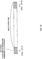
- FIG. 16 shows an overview of search processing on the division point in equation 11. It is assumed that the state portion in FIG. 16 is x i , and the length from the tail-end portion of a frame to the state portion, that is, a portion of the order of the filter is y i+L . However, for simplicity of description, a case will be described where processing is performed in frame units, not in subframe units.
- equation 11 shows a variation of frame energy when the target range of correlation operation is shifted by one sample at a time. Therefore, a point that maximizes equation 11 is a point at which the variation of frame energy is largest, and when grouping section 2012 divides the group at that point, it is possible to statistically reduce the number of errors in correlation operation accompanying the grouping.
- FIG. 16 shows a configuration during frame processing, and during subframe processing, the start position (start k ) of each subframe may be added to the start positions of x i and y i+L and the division point can be obtained using the same method as that described above.
- performing approximate auto-correlation operation in a configuration in which frame energy or subframe energy of an input signal is calculated using auto-correlation operations makes it possible to drastically reduce the amount of processing calculation (amount of calculation) without causing deterioration of the accuracy of frame energy or subframe energy.
- adaptively determining the approximation method of auto-correlation operation processing in processing frame (or subframe) units makes it possible to further suppress deterioration of the accuracy of frame energy or subframe energy.
- the present example has described a configuration in which some groups of a Toeplitz matrix are divided as shown in FIG. 14 as an example, it it is not limited to this and is likewise applicable to a case where all groups of the Toeplitz matrix are divided, or to a case of grouping other than a Toeplitz matrix (for example, the case of grouping as shown in FIG. 9 ).
- each group each subgroup
- a typical value of each group (each subgroup) of a grouped auto-correlation matrix it is possible to calculate a typical value as described previously.
- an auto-correlation operation value corresponding to the left top element of each group (each subgroup) may be assumed to be a typical value of each group (each subgroup).
- an auto-correlation operation value corresponding to the central element of each group may be assumed to be a typical value, and it is thereby possible to statistically reduce an error in auto-correlation operation with respect to the entire auto-correlation matrix.
- the coding apparatus is not limited to the above embodiment, but may be implemented modified in various ways in accordance with the claims.
- the decoding apparatus has been assumed to perform processing using encoded information transmitted from the coding apparatus encoded information containing necessary parameter or data can be processed even if it is not necessarily encoded information from the coding apparatus.
- the present invention is also applicable to cases where a signal processing program is written into a mechanically readable recording medium such as memory, disk, tape, CD, DVD and operated, and operations and effects similar to those in the above embodiment may be obtained.
- Each function block employed in the description of the aforementioned embodiment may typically be implemented as an LSI constituted by an integrated circuit. These may be individual chips or partially or totally contained referred to as "IC,” “system LSI,” “super LSI,” or “ultra LSI” depending on differing extents of integration.
- circuit integration is not limited to LSI's, and implementation using dedicated circuitry or general purpose processors is also possible.
- LSI manufacture utilization of a programmable FPGA (Field Programmable Gate Array) or a reconfigurable processor where connections and settings of circuit cells within an LSI can be reconfigured is also possible.
- FPGA Field Programmable Gate Array
- the coding apparatus can efficiently reduce the amount of operation when calculating frame energy or subframe energy of an input signal using auto-correlations and are applicable to, for example, a communication system or mobile communication system.
Landscapes
- Engineering & Computer Science (AREA)
- Computational Linguistics (AREA)
- Signal Processing (AREA)
- Health & Medical Sciences (AREA)
- Audiology, Speech & Language Pathology (AREA)
- Human Computer Interaction (AREA)
- Physics & Mathematics (AREA)
- Acoustics & Sound (AREA)
- Multimedia (AREA)
- Compression, Expansion, Code Conversion, And Decoders (AREA)
Claims (3)
- Kodierungsvorrichtung, die umfasst:einen Energieberechnungsabschnitt, der dazu eingerichtet ist, eines aus einer Rahmenenergie und einer Unterrahmenenergie eines Sprach-/Tonsignals unter Verwendung einer Autokorrelationsoperation zu berechnen; undeinen Kodierungsabschnitt, der dazu eingerichtet ist, das Sprach-/Tonsignal unter Verwendung von einem aus der Rahmenenergie und der Unterrahmenenergie zu kodieren und kodierte Informationen zu erzeugen, wobeiwobei der Energieberechnungsabschnitt dazu eingerichtet ist, die Steuerung so durchzuführen, dass die Anzahl der Kombinationen aus j und m, die durch Autokorrelationsoperationen an der Kombination aus j' und m' ersetzt werden, erhöht wird, wenn die Differenz zwischen j und m in Gleichung 1 oder Gleichung 2 zunimmt.
der Energieberechnungsabschnitt beim Durchführen einer Autokorrelationsoperation an dem Sprach-/Tonsignal unter Verwendung von Gleichung 1 oder Gleichung 2 dazu eingerichtet ist, Autokorrelationsoperationen 〈∑ ixi-j'xi-m' 〉 an einer Kombination aus j' und m' für eine Annäherung durchzuführen, die sich von einer Kombination aus j und m unterscheidet, entsprechend den Werten von j und m, und eines aus der Rahmenenergie und der Unterrahmenenergie durch Ersetzen der Autokorrelationsoperationen 〈∑ ixi-jxi-m 〉 an der Kombination aus j und m durch die Autokorrelationsoperationen an der Kombination aus j' und m' zu berechnen:[1]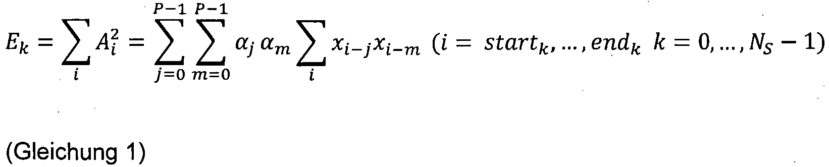 Ek: Energie (Unterrahmenenergie) des Unterrahmens, dessen Unterrahmenindex k ist,Aj: Sprach-/Tonsignal nach Filterung,P: Filterreihenfolge,αj, αm: Filterkoeffizient,xn: (n+1)-tes Sprach-/Tonsignal des Unterrahmens,j, m: Index, der eine Verzögerungszeit anzeigt, wenn die Autokorrelation berechnet wird,i: Probenindex des Sprach-/Tonsignals,Ns: Anzahl der Unterrahmen,k: Unterrahmenindex,startk: vorderer Probenindex des Unterrahmens, dessen Unterrahmenindex k ist, undendk: hinterer Probenindex des Unterrahmens, dessen Unterrahmenindex k ist; und[2]
 E: RahmenenergieAi: Sprach-/Tonsignal nach Filterung,P: Filterreihenfolge,αj, αm: Filterkoeffizient,xn: (n+1)-tes Sprach-/Tonsignal des Rahmens,j, m: Index, der eine Verzögerungszeit anzeigt, wenn die Autokorrelation berechnet wird,i: Probenindex des Sprach-/Tonsignals,start: vorderer Probenindex des Rahmens, undend: hinterer Probenindex des Rahmens, und
 - Kommunikations-Endgerätvorrichtung, die die Kodierungsvorrichtung nach Anspruch 1 umfasst.
- Basisstationsvorrichtung, die die Kodierungsvorrichtung nach Anspruch 1 umfasst.
Priority Applications (1)
| Application Number | Priority Date | Filing Date | Title |
|---|---|---|---|
| EP17159708.1A EP3285253B1 (de) | 2011-01-14 | 2011-12-14 | Verfahren zur kodierung eines sprach-/tonsignal |
Applications Claiming Priority (3)
| Application Number | Priority Date | Filing Date | Title |
|---|---|---|---|
| JP2011006211 | 2011-01-14 | ||
| JP2011054919 | 2011-03-14 | ||
| PCT/JP2011/006981 WO2012095924A1 (ja) | 2011-01-14 | 2011-12-14 | 符号化装置、通信処理装置および符号化方法 |
Related Child Applications (1)
| Application Number | Title | Priority Date | Filing Date |
|---|---|---|---|
| EP17159708.1A Division EP3285253B1 (de) | 2011-01-14 | 2011-12-14 | Verfahren zur kodierung eines sprach-/tonsignal |
Publications (3)
| Publication Number | Publication Date |
|---|---|
| EP2665060A1 EP2665060A1 (de) | 2013-11-20 |
| EP2665060A4 EP2665060A4 (de) | 2014-07-09 |
| EP2665060B1 true EP2665060B1 (de) | 2017-03-08 |
Family
ID=46506853
Family Applications (2)
| Application Number | Title | Priority Date | Filing Date |
|---|---|---|---|
| EP17159708.1A Active EP3285253B1 (de) | 2011-01-14 | 2011-12-14 | Verfahren zur kodierung eines sprach-/tonsignal |
| EP11855814.7A Not-in-force EP2665060B1 (de) | 2011-01-14 | 2011-12-14 | Gerät zur kodierung eines sprach-/tonsignal |
Family Applications Before (1)
| Application Number | Title | Priority Date | Filing Date |
|---|---|---|---|
| EP17159708.1A Active EP3285253B1 (de) | 2011-01-14 | 2011-12-14 | Verfahren zur kodierung eines sprach-/tonsignal |
Country Status (5)
| Country | Link |
|---|---|
| US (1) | US9324331B2 (de) |
| EP (2) | EP3285253B1 (de) |
| JP (1) | JP5722916B2 (de) |
| ES (1) | ES2627410T3 (de) |
| WO (1) | WO2012095924A1 (de) |
Family Cites Families (20)
| Publication number | Priority date | Publication date | Assignee | Title |
|---|---|---|---|---|
| JPH03236100A (ja) * | 1990-02-14 | 1991-10-22 | Toshiba Corp | 音声検出方式 |
| US5265190A (en) | 1991-05-31 | 1993-11-23 | Motorola, Inc. | CELP vocoder with efficient adaptive codebook search |
| US5179594A (en) | 1991-06-12 | 1993-01-12 | Motorola, Inc. | Efficient calculation of autocorrelation coefficients for CELP vocoder adaptive codebook |
| JPH06138896A (ja) * | 1991-05-31 | 1994-05-20 | Motorola Inc | 音声フレームを符号化するための装置および方法 |
| US5187745A (en) | 1991-06-27 | 1993-02-16 | Motorola, Inc. | Efficient codebook search for CELP vocoders |
| US5173941A (en) | 1991-05-31 | 1992-12-22 | Motorola, Inc. | Reduced codebook search arrangement for CELP vocoders |
| JPH0563580A (ja) | 1991-09-02 | 1993-03-12 | Mitsubishi Electric Corp | 音声信号処理方法 |
| JPH0830298A (ja) * | 1994-07-20 | 1996-02-02 | Hitachi Ltd | 音声符号化装置 |
| FR2729245B1 (fr) * | 1995-01-06 | 1997-04-11 | Lamblin Claude | Procede de codage de parole a prediction lineaire et excitation par codes algebriques |
| US6047254A (en) * | 1996-05-15 | 2000-04-04 | Advanced Micro Devices, Inc. | System and method for determining a first formant analysis filter and prefiltering a speech signal for improved pitch estimation |
| US5924062A (en) * | 1997-07-01 | 1999-07-13 | Nokia Mobile Phones | ACLEP codec with modified autocorrelation matrix storage and search |
| JP2947788B1 (ja) * | 1998-05-12 | 1999-09-13 | 日本電信電話株式会社 | 音声および音響信号の高速な符号化方法および装置および記録媒体 |
| US6959274B1 (en) * | 1999-09-22 | 2005-10-25 | Mindspeed Technologies, Inc. | Fixed rate speech compression system and method |
| US7376242B2 (en) * | 2001-03-22 | 2008-05-20 | Digimarc Corporation | Quantization-based data embedding in mapped data |
| US6766289B2 (en) | 2001-06-04 | 2004-07-20 | Qualcomm Incorporated | Fast code-vector searching |
| US6789059B2 (en) | 2001-06-06 | 2004-09-07 | Qualcomm Incorporated | Reducing memory requirements of a codebook vector search |
| JP2008158312A (ja) * | 2006-12-25 | 2008-07-10 | Oki Electric Ind Co Ltd | ピッチ推定器及びピッチ推定方法、並びに、自己相関演算器及び自己相関演算方法 |
| DE102008009718A1 (de) * | 2008-02-19 | 2009-08-20 | Siemens Enterprise Communications Gmbh & Co. Kg | Verfahren und Mittel zur Enkodierung von Hintergrundrauschinformationen |
| RU2621965C2 (ru) * | 2008-07-11 | 2017-06-08 | Фраунхофер-Гезелльшафт цур Фёрдерунг дер ангевандтен Форшунг Е.Ф. | Передатчик сигнала активации с деформацией по времени, кодер звукового сигнала, способ преобразования сигнала активации с деформацией по времени, способ кодирования звукового сигнала и компьютерные программы |
| CN101609678B (zh) * | 2008-12-30 | 2011-07-27 | 华为技术有限公司 | 信号压缩方法及其压缩装置 |
-
2011
- 2011-12-14 US US13/993,851 patent/US9324331B2/en active Active
- 2011-12-14 EP EP17159708.1A patent/EP3285253B1/de active Active
- 2011-12-14 ES ES11855814.7T patent/ES2627410T3/es active Active
- 2011-12-14 EP EP11855814.7A patent/EP2665060B1/de not_active Not-in-force
- 2011-12-14 WO PCT/JP2011/006981 patent/WO2012095924A1/ja not_active Ceased
- 2011-12-14 JP JP2012552542A patent/JP5722916B2/ja not_active Expired - Fee Related
Non-Patent Citations (1)
| Title |
|---|
| None * |
Also Published As
| Publication number | Publication date |
|---|---|
| EP2665060A1 (de) | 2013-11-20 |
| WO2012095924A1 (ja) | 2012-07-19 |
| US20130339009A1 (en) | 2013-12-19 |
| ES2627410T3 (es) | 2017-07-28 |
| US9324331B2 (en) | 2016-04-26 |
| EP3285253A1 (de) | 2018-02-21 |
| JPWO2012095924A1 (ja) | 2014-06-09 |
| EP2665060A4 (de) | 2014-07-09 |
| JP5722916B2 (ja) | 2015-05-27 |
| EP3285253B1 (de) | 2020-08-12 |
Similar Documents
| Publication | Publication Date | Title |
|---|---|---|
| EP2040251B1 (de) | Audiodekodierungseinrichtung und audiokodierungseinrichtung | |
| EP1326235B1 (de) | Quantisierung der Anregung in einem Geräuschrückkopplungskodierungssytem mit allgemeiner Rauschformung | |
| EP2234104B1 (de) | Vektorquantisierer, inverser vektorquantisierer und verfahren dafür | |
| US20110004469A1 (en) | Vector quantization device, vector inverse quantization device, and method thereof | |
| JPH1130997A (ja) | 音声符号化復号装置 | |
| CN101371299B (zh) | 固定码本搜索装置以及固定码本搜索方法 | |
| WO2008072736A1 (ja) | 適応音源ベクトル量子化装置および適応音源ベクトル量子化方法 | |
| KR20050020728A (ko) | 음성 처리 시스템, 음성 처리 방법 및 음성 프레임 평가방법 | |
| US7206740B2 (en) | Efficient excitation quantization in noise feedback coding with general noise shaping | |
| EP2101319B1 (de) | Einrichtung zur adaptiven schallquellen-vektorquantisierung und verfahren dafür | |
| JP5687706B2 (ja) | 量子化装置及び量子化方法 | |
| EP2770506A1 (de) | Kodiervorrichtung und kodierverfahren | |
| US8595000B2 (en) | Method and apparatus to search fixed codebook and method and apparatus to encode/decode a speech signal using the method and apparatus to search fixed codebook | |
| EP2665060B1 (de) | Gerät zur kodierung eines sprach-/tonsignal | |
| EP2116996A1 (de) | Kodiervorrichtung und kodierverfahren | |
| JP6001451B2 (ja) | 符号化装置及び符号化方法 | |
| KR100718487B1 (ko) | 디지털 음성 코더들에서의 고조파 잡음 가중 | |
| US9230553B2 (en) | Fixed codebook searching by closed-loop search using multiplexed loop | |
| JP3092436B2 (ja) | 音声符号化装置 | |
| EP2490217A1 (de) | Kodiervorrichtung, dekodiervorrichtung und verfahren dafür |
Legal Events
| Date | Code | Title | Description |
|---|---|---|---|
| PUAI | Public reference made under article 153(3) epc to a published international application that has entered the european phase |
Free format text: ORIGINAL CODE: 0009012 |
|
| 17P | Request for examination filed |
Effective date: 20130701 |
|
| AK | Designated contracting states |
Kind code of ref document: A1 Designated state(s): AL AT BE BG CH CY CZ DE DK EE ES FI FR GB GR HR HU IE IS IT LI LT LU LV MC MK MT NL NO PL PT RO RS SE SI SK SM TR |
|
| DAX | Request for extension of the european patent (deleted) | ||
| A4 | Supplementary search report drawn up and despatched |
Effective date: 20140606 |
|
| RIC1 | Information provided on ipc code assigned before grant |
Ipc: G10L 25/06 20130101ALN20140602BHEP Ipc: G10L 19/00 20130101AFI20140602BHEP Ipc: G10L 25/21 20130101ALN20140602BHEP |
|
| RAP1 | Party data changed (applicant data changed or rights of an application transferred) |
Owner name: PANASONIC INTELLECTUAL PROPERTY CORPORATION OF AME |
|
| 17Q | First examination report despatched |
Effective date: 20151111 |
|
| REG | Reference to a national code |
Ref country code: DE Ref legal event code: R079 Ref document number: 602011035824 Country of ref document: DE Free format text: PREVIOUS MAIN CLASS: G10L0019140000 Ipc: G10L0019000000 |
|
| GRAP | Despatch of communication of intention to grant a patent |
Free format text: ORIGINAL CODE: EPIDOSNIGR1 |
|
| RIC1 | Information provided on ipc code assigned before grant |
Ipc: G10L 25/06 20130101ALN20160902BHEP Ipc: G10L 19/00 20130101AFI20160902BHEP Ipc: G10L 25/21 20130101ALN20160902BHEP |
|
| INTG | Intention to grant announced |
Effective date: 20160930 |
|
| GRAS | Grant fee paid |
Free format text: ORIGINAL CODE: EPIDOSNIGR3 |
|
| GRAA | (expected) grant |
Free format text: ORIGINAL CODE: 0009210 |
|
| AK | Designated contracting states |
Kind code of ref document: B1 Designated state(s): AL AT BE BG CH CY CZ DE DK EE ES FI FR GB GR HR HU IE IS IT LI LT LU LV MC MK MT NL NO PL PT RO RS SE SI SK SM TR |
|
| REG | Reference to a national code |
Ref country code: GB Ref legal event code: FG4D |
|
| REG | Reference to a national code |
Ref country code: CH Ref legal event code: EP Ref country code: AT Ref legal event code: REF Ref document number: 874173 Country of ref document: AT Kind code of ref document: T Effective date: 20170315 |
|
| REG | Reference to a national code |
Ref country code: IE Ref legal event code: FG4D |
|
| REG | Reference to a national code |
Ref country code: DE Ref legal event code: R096 Ref document number: 602011035824 Country of ref document: DE |
|
| REG | Reference to a national code |
Ref country code: DE Ref legal event code: R082 Ref document number: 602011035824 Country of ref document: DE Representative=s name: GRUENECKER PATENT- UND RECHTSANWAELTE PARTG MB, DE Ref country code: DE Ref legal event code: R081 Ref document number: 602011035824 Country of ref document: DE Owner name: III HOLDINGS 12, LLC, WILMINGTON, US Free format text: FORMER OWNER: PANASONIC INTELLECTUAL PROPERTY CORPORATION OF AMERICA, TORRANCE, CALIF., US |
|
| REG | Reference to a national code |
Ref country code: NL Ref legal event code: FP |
|
| RAP2 | Party data changed (patent owner data changed or rights of a patent transferred) |
Owner name: III HOLDINGS 12, LLC |
|
| REG | Reference to a national code |
Ref country code: LT Ref legal event code: MG4D |
|
| REG | Reference to a national code |
Ref country code: ES Ref legal event code: FG2A Ref document number: 2627410 Country of ref document: ES Kind code of ref document: T3 Effective date: 20170728 |
|
| PG25 | Lapsed in a contracting state [announced via postgrant information from national office to epo] |
Ref country code: GR Free format text: LAPSE BECAUSE OF FAILURE TO SUBMIT A TRANSLATION OF THE DESCRIPTION OR TO PAY THE FEE WITHIN THE PRESCRIBED TIME-LIMIT Effective date: 20170609 Ref country code: LT Free format text: LAPSE BECAUSE OF FAILURE TO SUBMIT A TRANSLATION OF THE DESCRIPTION OR TO PAY THE FEE WITHIN THE PRESCRIBED TIME-LIMIT Effective date: 20170308 Ref country code: HR Free format text: LAPSE BECAUSE OF FAILURE TO SUBMIT A TRANSLATION OF THE DESCRIPTION OR TO PAY THE FEE WITHIN THE PRESCRIBED TIME-LIMIT Effective date: 20170308 Ref country code: NO Free format text: LAPSE BECAUSE OF FAILURE TO SUBMIT A TRANSLATION OF THE DESCRIPTION OR TO PAY THE FEE WITHIN THE PRESCRIBED TIME-LIMIT Effective date: 20170608 Ref country code: FI Free format text: LAPSE BECAUSE OF FAILURE TO SUBMIT A TRANSLATION OF THE DESCRIPTION OR TO PAY THE FEE WITHIN THE PRESCRIBED TIME-LIMIT Effective date: 20170308 |
|
| REG | Reference to a national code |
Ref country code: AT Ref legal event code: MK05 Ref document number: 874173 Country of ref document: AT Kind code of ref document: T Effective date: 20170308 |
|
| REG | Reference to a national code |
Ref country code: GB Ref legal event code: 732E Free format text: REGISTERED BETWEEN 20170727 AND 20170802 |
|
| PG25 | Lapsed in a contracting state [announced via postgrant information from national office to epo] |
Ref country code: LV Free format text: LAPSE BECAUSE OF FAILURE TO SUBMIT A TRANSLATION OF THE DESCRIPTION OR TO PAY THE FEE WITHIN THE PRESCRIBED TIME-LIMIT Effective date: 20170308 Ref country code: BG Free format text: LAPSE BECAUSE OF FAILURE TO SUBMIT A TRANSLATION OF THE DESCRIPTION OR TO PAY THE FEE WITHIN THE PRESCRIBED TIME-LIMIT Effective date: 20170608 Ref country code: SE Free format text: LAPSE BECAUSE OF FAILURE TO SUBMIT A TRANSLATION OF THE DESCRIPTION OR TO PAY THE FEE WITHIN THE PRESCRIBED TIME-LIMIT Effective date: 20170308 Ref country code: RS Free format text: LAPSE BECAUSE OF FAILURE TO SUBMIT A TRANSLATION OF THE DESCRIPTION OR TO PAY THE FEE WITHIN THE PRESCRIBED TIME-LIMIT Effective date: 20170308 |
|
| REG | Reference to a national code |
Ref country code: NL Ref legal event code: PD Owner name: III HOLDINGS 12, LLC; US Free format text: DETAILS ASSIGNMENT: CHANGE OF OWNER(S), ASSIGNMENT; FORMER OWNER NAME: PANASONIC INTELLECTUAL PROPERTY CORPORATION OF AMERICA Effective date: 20170808 |
|
| PG25 | Lapsed in a contracting state [announced via postgrant information from national office to epo] |
Ref country code: SK Free format text: LAPSE BECAUSE OF FAILURE TO SUBMIT A TRANSLATION OF THE DESCRIPTION OR TO PAY THE FEE WITHIN THE PRESCRIBED TIME-LIMIT Effective date: 20170308 Ref country code: CZ Free format text: LAPSE BECAUSE OF FAILURE TO SUBMIT A TRANSLATION OF THE DESCRIPTION OR TO PAY THE FEE WITHIN THE PRESCRIBED TIME-LIMIT Effective date: 20170308 Ref country code: AT Free format text: LAPSE BECAUSE OF FAILURE TO SUBMIT A TRANSLATION OF THE DESCRIPTION OR TO PAY THE FEE WITHIN THE PRESCRIBED TIME-LIMIT Effective date: 20170308 Ref country code: EE Free format text: LAPSE BECAUSE OF FAILURE TO SUBMIT A TRANSLATION OF THE DESCRIPTION OR TO PAY THE FEE WITHIN THE PRESCRIBED TIME-LIMIT Effective date: 20170308 Ref country code: RO Free format text: LAPSE BECAUSE OF FAILURE TO SUBMIT A TRANSLATION OF THE DESCRIPTION OR TO PAY THE FEE WITHIN THE PRESCRIBED TIME-LIMIT Effective date: 20170308 |
|
| REG | Reference to a national code |
Ref country code: FR Ref legal event code: PLFP Year of fee payment: 7 |
|
| PG25 | Lapsed in a contracting state [announced via postgrant information from national office to epo] |
Ref country code: PL Free format text: LAPSE BECAUSE OF FAILURE TO SUBMIT A TRANSLATION OF THE DESCRIPTION OR TO PAY THE FEE WITHIN THE PRESCRIBED TIME-LIMIT Effective date: 20170308 Ref country code: IS Free format text: LAPSE BECAUSE OF FAILURE TO SUBMIT A TRANSLATION OF THE DESCRIPTION OR TO PAY THE FEE WITHIN THE PRESCRIBED TIME-LIMIT Effective date: 20170708 Ref country code: SM Free format text: LAPSE BECAUSE OF FAILURE TO SUBMIT A TRANSLATION OF THE DESCRIPTION OR TO PAY THE FEE WITHIN THE PRESCRIBED TIME-LIMIT Effective date: 20170308 Ref country code: PT Free format text: LAPSE BECAUSE OF FAILURE TO SUBMIT A TRANSLATION OF THE DESCRIPTION OR TO PAY THE FEE WITHIN THE PRESCRIBED TIME-LIMIT Effective date: 20170710 |
|
| REG | Reference to a national code |
Ref country code: DE Ref legal event code: R097 Ref document number: 602011035824 Country of ref document: DE |
|
| PLBE | No opposition filed within time limit |
Free format text: ORIGINAL CODE: 0009261 |
|
| STAA | Information on the status of an ep patent application or granted ep patent |
Free format text: STATUS: NO OPPOSITION FILED WITHIN TIME LIMIT |
|
| PG25 | Lapsed in a contracting state [announced via postgrant information from national office to epo] |
Ref country code: DK Free format text: LAPSE BECAUSE OF FAILURE TO SUBMIT A TRANSLATION OF THE DESCRIPTION OR TO PAY THE FEE WITHIN THE PRESCRIBED TIME-LIMIT Effective date: 20170308 |
|
| 26N | No opposition filed |
Effective date: 20171211 |
|
| PG25 | Lapsed in a contracting state [announced via postgrant information from national office to epo] |
Ref country code: SI Free format text: LAPSE BECAUSE OF FAILURE TO SUBMIT A TRANSLATION OF THE DESCRIPTION OR TO PAY THE FEE WITHIN THE PRESCRIBED TIME-LIMIT Effective date: 20170308 |
|
| REG | Reference to a national code |
Ref country code: CH Ref legal event code: PL |
|
| REG | Reference to a national code |
Ref country code: IE Ref legal event code: MM4A |
|
| PG25 | Lapsed in a contracting state [announced via postgrant information from national office to epo] |
Ref country code: MT Free format text: LAPSE BECAUSE OF NON-PAYMENT OF DUE FEES Effective date: 20171214 Ref country code: LU Free format text: LAPSE BECAUSE OF NON-PAYMENT OF DUE FEES Effective date: 20171214 |
|
| REG | Reference to a national code |
Ref country code: BE Ref legal event code: MM Effective date: 20171231 |
|
| PG25 | Lapsed in a contracting state [announced via postgrant information from national office to epo] |
Ref country code: IE Free format text: LAPSE BECAUSE OF NON-PAYMENT OF DUE FEES Effective date: 20171214 |
|
| PG25 | Lapsed in a contracting state [announced via postgrant information from national office to epo] |
Ref country code: BE Free format text: LAPSE BECAUSE OF NON-PAYMENT OF DUE FEES Effective date: 20171231 Ref country code: CH Free format text: LAPSE BECAUSE OF NON-PAYMENT OF DUE FEES Effective date: 20171231 Ref country code: LI Free format text: LAPSE BECAUSE OF NON-PAYMENT OF DUE FEES Effective date: 20171231 |
|
| PG25 | Lapsed in a contracting state [announced via postgrant information from national office to epo] |
Ref country code: MC Free format text: LAPSE BECAUSE OF FAILURE TO SUBMIT A TRANSLATION OF THE DESCRIPTION OR TO PAY THE FEE WITHIN THE PRESCRIBED TIME-LIMIT Effective date: 20170308 Ref country code: HU Free format text: LAPSE BECAUSE OF FAILURE TO SUBMIT A TRANSLATION OF THE DESCRIPTION OR TO PAY THE FEE WITHIN THE PRESCRIBED TIME-LIMIT; INVALID AB INITIO Effective date: 20111214 |
|
| PG25 | Lapsed in a contracting state [announced via postgrant information from national office to epo] |
Ref country code: CY Free format text: LAPSE BECAUSE OF NON-PAYMENT OF DUE FEES Effective date: 20170308 |
|
| PG25 | Lapsed in a contracting state [announced via postgrant information from national office to epo] |
Ref country code: MK Free format text: LAPSE BECAUSE OF FAILURE TO SUBMIT A TRANSLATION OF THE DESCRIPTION OR TO PAY THE FEE WITHIN THE PRESCRIBED TIME-LIMIT Effective date: 20170308 |
|
| PG25 | Lapsed in a contracting state [announced via postgrant information from national office to epo] |
Ref country code: TR Free format text: LAPSE BECAUSE OF FAILURE TO SUBMIT A TRANSLATION OF THE DESCRIPTION OR TO PAY THE FEE WITHIN THE PRESCRIBED TIME-LIMIT Effective date: 20170308 |
|
| PG25 | Lapsed in a contracting state [announced via postgrant information from national office to epo] |
Ref country code: AL Free format text: LAPSE BECAUSE OF FAILURE TO SUBMIT A TRANSLATION OF THE DESCRIPTION OR TO PAY THE FEE WITHIN THE PRESCRIBED TIME-LIMIT Effective date: 20170308 |
|
| PGFP | Annual fee paid to national office [announced via postgrant information from national office to epo] |
Ref country code: GB Payment date: 20211221 Year of fee payment: 11 Ref country code: FR Payment date: 20211227 Year of fee payment: 11 |
|
| PGFP | Annual fee paid to national office [announced via postgrant information from national office to epo] |
Ref country code: IT Payment date: 20211220 Year of fee payment: 11 |
|
| PGFP | Annual fee paid to national office [announced via postgrant information from national office to epo] |
Ref country code: NL Payment date: 20211229 Year of fee payment: 11 |
|
| PGFP | Annual fee paid to national office [announced via postgrant information from national office to epo] |
Ref country code: DE Payment date: 20211228 Year of fee payment: 11 |
|
| PGFP | Annual fee paid to national office [announced via postgrant information from national office to epo] |
Ref country code: ES Payment date: 20220110 Year of fee payment: 11 |
|
| REG | Reference to a national code |
Ref country code: DE Ref legal event code: R119 Ref document number: 602011035824 Country of ref document: DE |
|
| REG | Reference to a national code |
Ref country code: NL Ref legal event code: MM Effective date: 20230101 |
|
| GBPC | Gb: european patent ceased through non-payment of renewal fee |
Effective date: 20221214 |
|
| PG25 | Lapsed in a contracting state [announced via postgrant information from national office to epo] |
Ref country code: NL Free format text: LAPSE BECAUSE OF NON-PAYMENT OF DUE FEES Effective date: 20230101 |
|
| PG25 | Lapsed in a contracting state [announced via postgrant information from national office to epo] |
Ref country code: GB Free format text: LAPSE BECAUSE OF NON-PAYMENT OF DUE FEES Effective date: 20221214 Ref country code: DE Free format text: LAPSE BECAUSE OF NON-PAYMENT OF DUE FEES Effective date: 20230701 |
|
| PG25 | Lapsed in a contracting state [announced via postgrant information from national office to epo] |
Ref country code: FR Free format text: LAPSE BECAUSE OF NON-PAYMENT OF DUE FEES Effective date: 20221231 |
|
| PG25 | Lapsed in a contracting state [announced via postgrant information from national office to epo] |
Ref country code: IT Free format text: LAPSE BECAUSE OF NON-PAYMENT OF DUE FEES Effective date: 20221214 |
|
| REG | Reference to a national code |
Ref country code: ES Ref legal event code: FD2A Effective date: 20240201 |
|
| PG25 | Lapsed in a contracting state [announced via postgrant information from national office to epo] |
Ref country code: ES Free format text: LAPSE BECAUSE OF NON-PAYMENT OF DUE FEES Effective date: 20221215 |
|
| PG25 | Lapsed in a contracting state [announced via postgrant information from national office to epo] |
Ref country code: ES Free format text: LAPSE BECAUSE OF NON-PAYMENT OF DUE FEES Effective date: 20221215 |