EP2665189A1 - Panneau bouton-poussoir pour contrôle capacitif pour série électrique résidentielle - Google Patents
Panneau bouton-poussoir pour contrôle capacitif pour série électrique résidentielle Download PDFInfo
- Publication number
- EP2665189A1 EP2665189A1 EP13167731.2A EP13167731A EP2665189A1 EP 2665189 A1 EP2665189 A1 EP 2665189A1 EP 13167731 A EP13167731 A EP 13167731A EP 2665189 A1 EP2665189 A1 EP 2665189A1
- Authority
- EP
- European Patent Office
- Prior art keywords
- push
- button panel
- front panel
- areas
- panel according
- Prior art date
- Legal status (The legal status is an assumption and is not a legal conclusion. Google has not performed a legal analysis and makes no representation as to the accuracy of the status listed.)
- Withdrawn
Links
- 239000011521 glass Substances 0.000 claims description 10
- 229920005372 Plexiglas® Polymers 0.000 claims description 2
- 239000004926 polymethyl methacrylate Substances 0.000 claims description 2
- 238000005516 engineering process Methods 0.000 description 3
- 238000007650 screen-printing Methods 0.000 description 2
- RYGMFSIKBFXOCR-UHFFFAOYSA-N Copper Chemical compound [Cu] RYGMFSIKBFXOCR-UHFFFAOYSA-N 0.000 description 1
- 238000004026 adhesive bonding Methods 0.000 description 1
- 230000005540 biological transmission Effects 0.000 description 1
- 230000001276 controlling effect Effects 0.000 description 1
- 229910052802 copper Inorganic materials 0.000 description 1
- 239000010949 copper Substances 0.000 description 1
- 230000001419 dependent effect Effects 0.000 description 1
- 238000001514 detection method Methods 0.000 description 1
- 238000005286 illumination Methods 0.000 description 1
- 230000001939 inductive effect Effects 0.000 description 1
- 238000009434 installation Methods 0.000 description 1
- 239000000463 material Substances 0.000 description 1
- 230000003287 optical effect Effects 0.000 description 1
- 230000001105 regulatory effect Effects 0.000 description 1
- 239000000758 substrate Substances 0.000 description 1
Images


Classifications
-
- H—ELECTRICITY
- H03—ELECTRONIC CIRCUITRY
- H03K—PULSE TECHNIQUE
- H03K17/00—Electronic switching or gating, i.e. not by contact-making and –breaking
- H03K17/94—Electronic switching or gating, i.e. not by contact-making and –breaking characterised by the way in which the control signals are generated
- H03K17/96—Touch switches
- H03K17/962—Capacitive touch switches
- H03K17/9622—Capacitive touch switches using a plurality of detectors, e.g. keyboard
-
- H—ELECTRICITY
- H03—ELECTRONIC CIRCUITRY
- H03K—PULSE TECHNIQUE
- H03K2217/00—Indexing scheme related to electronic switching or gating, i.e. not by contact-making or -breaking covered by H03K17/00
- H03K2217/94—Indexing scheme related to electronic switching or gating, i.e. not by contact-making or -breaking covered by H03K17/00 characterised by the way in which the control signal is generated
- H03K2217/96—Touch switches
- H03K2217/9607—Capacitive touch switches
- H03K2217/960755—Constructional details of capacitive touch and proximity switches
-
- H—ELECTRICITY
- H03—ELECTRONIC CIRCUITRY
- H03K—PULSE TECHNIQUE
- H03K2217/00—Indexing scheme related to electronic switching or gating, i.e. not by contact-making or -breaking covered by H03K17/00
- H03K2217/94—Indexing scheme related to electronic switching or gating, i.e. not by contact-making or -breaking covered by H03K17/00 characterised by the way in which the control signal is generated
- H03K2217/96—Touch switches
- H03K2217/9607—Capacitive touch switches
- H03K2217/960785—Capacitive touch switches with illumination
Definitions
- the object of the present invention is a capacitive control push-button panel for residential electrical series, which can be configured according to the electrical loads which are to be controlled.
- the residential electrical series currently existing on the market provide, in almost all cases, electromechanical controls for actuating electrical devices (wallplates) such as switches, change-over switches, diverters, dimmers, etc.
- the wallplates are housed in a flush-mount box, mounted on a special support frame, with the control members projecting frontally enclosed in an external cover plate with mainly aesthetic function.
- controls of the capacitive type which provide an external covering, normally in glass, below which a printed circuit is placed with conductive copper areas and sensors, in such a way that by touching with a finger the glass covering in certain zones appropriately screen-printed externally a variation in capacity is produced with which the associated load is controlled.
- US5239152 describes a panel with capacitive tactile sensor provided with graphic symbols/alphanumerical characters and defined by a dielectric flat substrate comprising a plurality of layers, an optical filter, a light source for the lighting of the graphic symbols, and means of capacitive sensorisation juxtaposed on said graphic symbols for the detection of the touch/pressure exerted by the user on the panel and the transmission of the relative signal to switches for enabling specific controls/functions.
- US2005/0134485 describes a tactile panel used on a motor vehicle comprising at least one area associated to said panel and at least one non-mechanical switch of the resistive, inductive, capacitive or piezoelectric type placed to the rear of this area and suitable for enabling/disabling electrically a specific device of the vehicle, with said area associated to a sensitive region of the switch, the panel provided with sources of LED lighting associated to the indicators of the switches.
- the object of the invention is that of eliminating the disadvantages of the control systems for residential series, both electromechanical and capacitive, providing a push-button panel which is able to modify easily its interface and have on each occasion a different function.
- Another object of the invention is that of providing such a push-button panel which can be configured as a function of the different electrical needs, without having to modify, add, replace components.
- Yet another object of the invention is that of providing such a push-button panel which can be preset with different configurations which can be activated selectively for the control of different loads.
- the capacitive control push-button panel for residential electrical series comprises a front panel, preferably in opaque glass, with screen-printed on the rear a plurality of icons arranged so as to cover all possible control configurations; a rear CapSense printed circuit board with a plurality of sensitive areas, each of which can be associated to a desired command, and a plurality of back-lit balls arranged in perfect alignment with said plurality of icons provided on the rear of the front panel; said sensitive areas can be selectively activated by software, so as to determine a particular push-button panel configuration, with lighting of corresponding icons on the front panel, touching or skimming which a relative load is controlled.
- the push-button panel according to the invention also comprises a board of interface to a home automation bus, such as SimpleHome, Technobus, Eyelink protocol bus.
- a home automation bus such as SimpleHome, Technobus, Eyelink protocol bus.
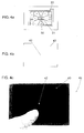
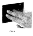
- the capacitive electronics of the push-button panel is able to recognise some gestures, in particular the gesture of passing the hand over the front panel allows a "page change" and therefore a different configuration of the controls of the push-button panel to be activated.
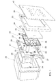
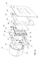
- reference numeral 10 denotes the capacitive control push-button panel for residential electrical series according to the invention, which in this case is schematically illustrated exploded for the assembly in a usual flush-mount wall box 20, by means of a support frame 21, which has the shape of a square or rectangular frame, which in a manner in itself known is attached to the box 1 for example by means of screws, not shown, inserted in slots or holes 23 provided in the frame 21 and screwing in seats 24 provided in the box 20.
- the support frame 21 has a circular central opening 25, so as to be able to adapt both to a rectangular box ( Fig. 1 ) and a round box ( Fig. 1a ).
- the push-button panel in itself comprises substantially a printed circuit board 30 and a front panel 40, which in the preferred embodiment is in opaque glass, but which obviously could be in any other suitable material such as Plexiglas and the like.
- a mask 22 can also be seen in the form of a rectangular frame which is attached for example by gluing on the back of the front panel 40 and/or carries means for the attachment for example by slotting to the support frame 21.
- these means are made up of teeth 26 which engage in corresponding holes 27 provided in the support frame 21.
- the printed circuit board 30 also carries means of hooking to the support frame 21, made up in this case by holes 38 engaging with pins 28 projecting frontally from the support frame 21.
- Figures 1 and 1a also show a diffusing screen 50 placed frontally to the board 30, suitable for improving and making more uniform the emission of the LEDs provided on the back of the board 30, as will be stated herein below.
- the screen 50 covers the printed circuit board 30 and is attached to the support frame 21 by means of teeth 59 which engage in corresponding seats 29 of the frame 21.
- Figs. 1 and 1a are purely indicative, and the push-button panel 10 according to the invention, constituted substantially by the printed circuit board 30 and by the front panel 40, can be mounted in any other way, making the necessary electrical connections not shown in the drawings.
- Fig. 2 is a plan view of the printed circuit board 30, shown in a configuration slightly different from that of Figures 1 and 1a .
- the particular configuration of the board 30 is not essential for the purpose of the present invention. It has a plurality of sensitive areas, denoted generically by reference numeral 31, distributed practically over the entire surface of the board.
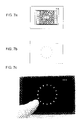
- each of said sensitive areas 31 at least one back-lit, in particular by means of an RGB LED, ball 32 is provided.
- a back-lit ball 32 is provided also between pairs of adjacent polygonal areas, so as to form, together with other balls provided in these areas, a circumferential contour.
- the back-lighting RGB LEDs 32 when lit, highlight the corresponding areas or active keys.
- three small rectangles 33 are provided which represent the same number of back-lighting RGB LEDs which in the case in question identify the page in use with respect to three available.
- Fig. 3 is a plan view of the front opaque glass panel 40 with all the icons shown, denoted by reference numeral 42, screen-printed on the back of the same, which are arranged in perfect alignment with the underlying back-lighting RGB LEDs 32, in such a way that, on the basis of the chosen configuration, the icons corresponding to the control keys activated are highlighted, as will be described briefly herein below.
- the printed circuit board 30 generically indicated in the drawings is in practice made up of two or three boards: one front base board which performs the functions of management of the capacitive part for the definition of the sensitive areas 31 and for the management of the RGB LEDs 32, and a rear plug-in board of interface towards a home automation bus with communications in Technobus, SimpleHome, Eyelink protocol and the like.
- the board of capacitive management of the sensitive areas can be separated from that of the LEDs, thus bringing to three the number of the sandwich boards.
- the configurations used in the phase of functioning are defined during the phase of set-up of the system, selecting them from software.
- the back-lighting LEDs 32 are of the RGB type, so as to be able to light with a different colour the icons corresponding to the active keys, as a function of the status of the same, for example blue for the off status and red for the on status.
- a feedback may be provided at the time of pressing or skimming of an active key, for example a micro-vibration of the push-button panel and/or a sound.
- a luminosity sensor may also be provided which provides for regulating, if enabled, the intensity of the LEDs of identification of the various push-buttons.
- the front panel 40 can be provided normally with the back-light illumination switched off and the push-buttons positioning LEDs switched off. In this case both the back-light and the push-buttons light up to represent the possible state of the load, by bringing a hand close, and switch off again after a timeout time which can be set from software.
Landscapes
- Push-Button Switches (AREA)
- Circuit Arrangement For Electric Light Sources In General (AREA)
Applications Claiming Priority (1)
| Application Number | Priority Date | Filing Date | Title |
|---|---|---|---|
| IT000850A ITMI20120850A1 (it) | 2012-05-16 | 2012-05-16 | Pulsantiera di comando capacitiva per serie elettriche civili |
Publications (1)
| Publication Number | Publication Date |
|---|---|
| EP2665189A1 true EP2665189A1 (fr) | 2013-11-20 |
Family
ID=46178663
Family Applications (1)
| Application Number | Title | Priority Date | Filing Date |
|---|---|---|---|
| EP13167731.2A Withdrawn EP2665189A1 (fr) | 2012-05-16 | 2013-05-14 | Panneau bouton-poussoir pour contrôle capacitif pour série électrique résidentielle |
Country Status (2)
| Country | Link |
|---|---|
| EP (1) | EP2665189A1 (fr) |
| IT (1) | ITMI20120850A1 (fr) |
Cited By (5)
| Publication number | Priority date | Publication date | Assignee | Title |
|---|---|---|---|---|
| EP3073338A1 (fr) | 2015-03-26 | 2016-09-28 | Niko NV | Dispositif de commande intelligent |
| US20210281262A1 (en) * | 2018-07-31 | 2021-09-09 | Micro Motion, Inc. | Capacitive button interface assembly |
| EP4312371A1 (fr) * | 2022-07-26 | 2024-01-31 | Abb Schweiz Ag | Élément de commande paramétrable assisté par l'éclairage et procédé de paramétrage d'un élément de commande assisté par l'éclairage pour des installations de construction |
| EP4312372A1 (fr) * | 2022-07-26 | 2024-01-31 | Abb Schweiz Ag | Tableau de commande paramétrable et procédé de paramétrage d'un tableau de commande pour des installations de bâtiment |
| EP4312373A1 (fr) * | 2022-07-26 | 2024-01-31 | Abb Schweiz Ag | Élément de commande à éclairage, et procédé de commande à éclairage pour des installations de construction |
Citations (5)
| Publication number | Priority date | Publication date | Assignee | Title |
|---|---|---|---|---|
| US5239152A (en) | 1990-10-30 | 1993-08-24 | Donnelly Corporation | Touch sensor panel with hidden graphic mode |
| GB2388904A (en) * | 2002-01-26 | 2003-11-26 | Audix Broadcast Ltd | Touch-sensitive illuminated control element |
| US20050134485A1 (en) | 2003-12-22 | 2005-06-23 | Hein David A. | Touch pad for motor vehicle and sensor therewith |
| US20050179672A1 (en) * | 2004-02-17 | 2005-08-18 | Yen-Chang Chiu | Simplified capacitive touchpad and method thereof |
| EP2385630A2 (fr) * | 2010-05-04 | 2011-11-09 | Whirlpool Corporation | Interface d'utilisateur activé au toucher |
-
2012
- 2012-05-16 IT IT000850A patent/ITMI20120850A1/it unknown
-
2013
- 2013-05-14 EP EP13167731.2A patent/EP2665189A1/fr not_active Withdrawn
Patent Citations (5)
| Publication number | Priority date | Publication date | Assignee | Title |
|---|---|---|---|---|
| US5239152A (en) | 1990-10-30 | 1993-08-24 | Donnelly Corporation | Touch sensor panel with hidden graphic mode |
| GB2388904A (en) * | 2002-01-26 | 2003-11-26 | Audix Broadcast Ltd | Touch-sensitive illuminated control element |
| US20050134485A1 (en) | 2003-12-22 | 2005-06-23 | Hein David A. | Touch pad for motor vehicle and sensor therewith |
| US20050179672A1 (en) * | 2004-02-17 | 2005-08-18 | Yen-Chang Chiu | Simplified capacitive touchpad and method thereof |
| EP2385630A2 (fr) * | 2010-05-04 | 2011-11-09 | Whirlpool Corporation | Interface d'utilisateur activé au toucher |
Cited By (6)
| Publication number | Priority date | Publication date | Assignee | Title |
|---|---|---|---|---|
| EP3073338A1 (fr) | 2015-03-26 | 2016-09-28 | Niko NV | Dispositif de commande intelligent |
| US20210281262A1 (en) * | 2018-07-31 | 2021-09-09 | Micro Motion, Inc. | Capacitive button interface assembly |
| US11784643B2 (en) * | 2018-07-31 | 2023-10-10 | Micro Motion, Inc. | Capacitive button interface assembly |
| EP4312371A1 (fr) * | 2022-07-26 | 2024-01-31 | Abb Schweiz Ag | Élément de commande paramétrable assisté par l'éclairage et procédé de paramétrage d'un élément de commande assisté par l'éclairage pour des installations de construction |
| EP4312372A1 (fr) * | 2022-07-26 | 2024-01-31 | Abb Schweiz Ag | Tableau de commande paramétrable et procédé de paramétrage d'un tableau de commande pour des installations de bâtiment |
| EP4312373A1 (fr) * | 2022-07-26 | 2024-01-31 | Abb Schweiz Ag | Élément de commande à éclairage, et procédé de commande à éclairage pour des installations de construction |
Also Published As
| Publication number | Publication date |
|---|---|
| ITMI20120850A1 (it) | 2013-11-17 |
Similar Documents
| Publication | Publication Date | Title |
|---|---|---|
| US20240222046A1 (en) | Control devices having independently suspended buttons for controlled actuation | |
| US6140987A (en) | User interface for home automation system | |
| EP2665189A1 (fr) | Panneau bouton-poussoir pour contrôle capacitif pour série électrique résidentielle | |
| CN107408943B (zh) | 触摸开关单元和包括该触摸开关单元的用于车辆的内部照明装置 | |
| US20160342210A1 (en) | Video Buttons for a Stage Lighting Console | |
| US20070018965A1 (en) | Illuminated touch control interface | |
| CN101595642B (zh) | 用于电子技术设备的输入单元 | |
| WO1997011448A1 (fr) | Interface utilisateur pour systeme domotique | |
| MX2008016238A (es) | Accionador táctil con retroalimentación sensorial. | |
| CN107111471A (zh) | 交通工具、用户界面和用于在两个显示装置上交叠地显示显示内容的方法 | |
| JP2009110912A (ja) | 調光操作器及び調光システム | |
| KR20110022665A (ko) | 소비자 부하를 제어하는 사용자 인터페이스 장치 및 이러한 사용자 인터페이스 장치를 사용하는 조명 시스템 | |
| US20100059348A1 (en) | Actuating element | |
| EP2849172B1 (fr) | Dispositif de commande et appareil électrique comportant un tel dispositif de commande | |
| JP2026011993A (ja) | パターン表示型タッチパネル構造 | |
| TWI507088B (zh) | 負載控制器 | |
| US6924465B2 (en) | Display device with illuminating device for a domestic electric heating apparatus | |
| JP4713210B2 (ja) | 静電容量式スイッチ装置 | |
| US11640216B2 (en) | Wall mounted control device with tactile and touch sensing button combination to increase button configurations | |
| AU2012325685B2 (en) | Touch dimmer lighting control | |
| US20170305572A1 (en) | Oled lighting for avionic keypanels | |
| ES2927679T3 (es) | Interfaz hombre-máquina de control táctil | |
| KR20210144310A (ko) | 차량용 통합형 메뉴 장치 | |
| CN211118881U (zh) | 一种汽车氛围灯 | |
| JP5333827B2 (ja) | 調光操作器及び調光システム |
Legal Events
| Date | Code | Title | Description |
|---|---|---|---|
| PUAI | Public reference made under article 153(3) epc to a published international application that has entered the european phase |
Free format text: ORIGINAL CODE: 0009012 |
|
| AK | Designated contracting states |
Kind code of ref document: A1 Designated state(s): AL AT BE BG CH CY CZ DE DK EE ES FI FR GB GR HR HU IE IS IT LI LT LU LV MC MK MT NL NO PL PT RO RS SE SI SK SM TR |
|
| AX | Request for extension of the european patent |
Extension state: BA ME |
|
| 17P | Request for examination filed |
Effective date: 20140307 |
|
| RBV | Designated contracting states (corrected) |
Designated state(s): AL AT BE BG CH CY CZ DE DK EE ES FI FR GB GR HR HU IE IS IT LI LT LU LV MC MK MT NL NO PL PT RO RS SE SI SK SM TR |
|
| 17Q | First examination report despatched |
Effective date: 20150528 |
|
| STAA | Information on the status of an ep patent application or granted ep patent |
Free format text: STATUS: THE APPLICATION IS DEEMED TO BE WITHDRAWN |
|
| 18D | Application deemed to be withdrawn |
Effective date: 20151008 |