EP4312372A1 - Tableau de commande paramétrable et procédé de paramétrage d'un tableau de commande pour des installations de bâtiment - Google Patents
Tableau de commande paramétrable et procédé de paramétrage d'un tableau de commande pour des installations de bâtiment Download PDFInfo
- Publication number
- EP4312372A1 EP4312372A1 EP22186968.8A EP22186968A EP4312372A1 EP 4312372 A1 EP4312372 A1 EP 4312372A1 EP 22186968 A EP22186968 A EP 22186968A EP 4312372 A1 EP4312372 A1 EP 4312372A1
- Authority
- EP
- European Patent Office
- Prior art keywords
- control pad
- area sensor
- capacitive area
- parametrizable
- operation function
- Prior art date
- Legal status (The legal status is an assumption and is not a legal conclusion. Google has not performed a legal analysis and makes no representation as to the accuracy of the status listed.)
- Pending
Links
Images


Classifications
-
- H—ELECTRICITY
- H03—ELECTRONIC CIRCUITRY
- H03K—PULSE TECHNIQUE
- H03K17/00—Electronic switching or gating, i.e. not by contact-making and –breaking
- H03K17/94—Electronic switching or gating, i.e. not by contact-making and –breaking characterised by the way in which the control signals are generated
- H03K17/96—Touch switches
- H03K17/962—Capacitive touch switches
- H03K17/9622—Capacitive touch switches using a plurality of detectors, e.g. keyboard
-
- H—ELECTRICITY
- H02—GENERATION; CONVERSION OR DISTRIBUTION OF ELECTRIC POWER
- H02G—INSTALLATION OF ELECTRIC CABLES OR LINES, OR OF COMBINED OPTICAL AND ELECTRIC CABLES OR LINES
- H02G3/00—Installations of electric cables or lines or protective tubing therefor in or on buildings, equivalent structures or vehicles
- H02G3/02—Details
- H02G3/08—Distribution boxes; Connection or junction boxes
- H02G3/12—Distribution boxes; Connection or junction boxes for flush mounting
-
- H—ELECTRICITY
- H02—GENERATION; CONVERSION OR DISTRIBUTION OF ELECTRIC POWER
- H02G—INSTALLATION OF ELECTRIC CABLES OR LINES, OR OF COMBINED OPTICAL AND ELECTRIC CABLES OR LINES
- H02G3/00—Installations of electric cables or lines or protective tubing therefor in or on buildings, equivalent structures or vehicles
- H02G3/02—Details
- H02G3/08—Distribution boxes; Connection or junction boxes
- H02G3/14—Fastening of cover or lid to box
-
- H—ELECTRICITY
- H03—ELECTRONIC CIRCUITRY
- H03K—PULSE TECHNIQUE
- H03K2217/00—Indexing scheme related to electronic switching or gating, i.e. not by contact-making or -breaking covered by H03K17/00
- H03K2217/94—Indexing scheme related to electronic switching or gating, i.e. not by contact-making or -breaking covered by H03K17/00 characterised by the way in which the control signal is generated
- H03K2217/94084—Transmission of parameters among sensors or between sensor and remote station
- H03K2217/94094—Wired transmission, e.g. via bus connection or similar
-
- H—ELECTRICITY
- H03—ELECTRONIC CIRCUITRY
- H03K—PULSE TECHNIQUE
- H03K2217/00—Indexing scheme related to electronic switching or gating, i.e. not by contact-making or -breaking covered by H03K17/00
- H03K2217/94—Indexing scheme related to electronic switching or gating, i.e. not by contact-making or -breaking covered by H03K17/00 characterised by the way in which the control signal is generated
- H03K2217/96—Touch switches
- H03K2217/9607—Capacitive touch switches
- H03K2217/960755—Constructional details of capacitive touch and proximity switches
Definitions
- the disclosure generally relates to a parametrizable control pad, and a parametrization method for a control pad for building installations.
- building installations refers to installations of interior as well as exterior spaces, such as lightening, air conditioning, heating, (rolling) shutters, blinds, comfort scenes, windows, or gates.
- the number, as well as type of building installations may vary from space to space, as well as over the lifetime of a building, for instance, due to renovation. Therefore, a great number of different control pads, each control pad reflecting the number of building installations in a space, may become necessary.
- modifications of building installation for instance due to a renovation, may render already present control pads useless, thereby requiring their replacement.
- a single, more versatile control pad which provides operating functions more flexibly may help to reduce resources of both, material and man hour.
- a control pad is provided with a fixed number of operating elements.
- control pads include, for instance, a one-fold, two- fold or multi- fold switch.
- Hardware permanently implements each of the fixed number of operating elements.
- Variants are typically realized via differences in electro-mechanics and/ or electronics between control pads. In electro-mechanics, variants are realized by a respective combination of individually pronounced pushbuttons, rockers or buttons. In electronics, variants are realized by a respective number of distinctive operating elements, as illustrated by Fig. 1 .
- Fig. 1 illustrates a schematic diagram of a control pad according to prior art.
- the control pad 100 provides six distinctive operating elements 10a - 10f. It may thus form the basis of a six-fold switch.
- the operation elements 10a - 10f are distinctively provided by a corresponding number of hardware components.
- the hardware components specify the number of operation elements 10a - 10f the control pad 100 can provide. Not all of the operation elements 10a - 10f need to be used.
- the control pad 100 may as well be implemented as a two-fold or four-fold switch by using only a corresponding number of the operation elements 10a - 10f.
- Each of the operation elements 10a - 10f may be used to control a building installation. For instance, operation element 10a may be used to control lightening, while operation element 10b may be used to control blinds.
- control pad 100 and its operation elements 10a - 10f are insufficient. It is, thus, favorable to provide a single, more versatile control pad, thereby extending its usage time and application range.
- a parametrizable control pad configured to control at least one building installation by a user.
- the control pad comprises a capacitive area sensor, and an interface unit which is configured to receive a parameterization for the capacitive area sensor.
- the parametrization comprises at least one operation function.
- the control pad further comprises a logic unit which is configured to parametrize the capacitive area sensor according to the parameterization. When parametrized according to the parameterization, the capacitive area sensor is configured to detect a user input to the at least one operation function.
- the logic unit is further configured to convert the user input to the at least one operation function into a control signal for the at least one building installation.
- Operation function may refer to a virtual representation of an operation element, such as a switch or a predefined input gesture by a user.
- the operation function serves as a flexible input interface that may be adjusted anytime by a respective parametrization using software code and/ or a parameter set. Thus, no hardware modifications are necessary for adjusting the control pad.
- one operation function may be used to control a single building installation, while, in other cases, a single operation function may be used to control a plurality of building installations.
- operation function generally refers herein to a virtual representation of an operation element.
- Parameterization may refer to a specification or configuration of the control pad.
- the parametrization may be provided as software code and/ or a parameter set that is to be implemented by the control unit.
- the implementation may be facilitated by a program, an application and/ or dedicated tool, that is publicly and/ or commercially available, such as the ETS software.
- the control signal may actuate one or more building installations or a specific function thereof. Examples include a control signal that causes a lamp to be switched on or off; brightness of a lamp to be increased or decreased; or a window to be opened or closed.
- an operation function may define the control signal to also include a specific time to elapse before actuating a building installation. For example, an operation function may define actuating a building installation in 1 minute in response to a user input.
- the parametrizable control pad may further comprise, in some embodiments, a BUS interface.
- the BUS interface may be integrated into a flush-mounted insert.
- the BUS interface is configured to transmit the control signal to a control system of the at least one building installation.
- the BUS interface may be adapted to communicate via KNX bus.
- the interface unit may be realized by the BUS interface.
- the control system of the building installation may refer, for instance, to a thermostat of a heating, or a motor control of blinds.
- a flush-mounted insert may also or alternatively include an actuator.
- the parametrizable control pad may comprise a wireless interface, such as a Bluetooth interface, that may serve as the interface unit and/ or for transmitting control signals to the building installations.
- the control pad may be powered by a flush-mounted insert to which it is connected to.
- the parameterization further comprises a type of each of the at least one operation function and/ or an arrangement of the at least one operation function within the capacitive area sensor.
- the arrangement specifies where the at least one operation element to be virtually represented is located within the surface of the capacitive area sensor.
- the arrangement may consider the number of the operation functions such that a single operation function is arranged more centrally and extensively within the capacitive area sensor, while a plurality of operation functions is arranged in smaller scale within the capacitive area sensor.
- the arrangement may as well limit the surface of the capacitive area sensor to an active area.
- the type of the operation functions may be the same or mutually different. Alternatively, the type of the operation functions may partially overlap such that some types of the operation functions are identical and some differ therefrom.
- the type of the operation functions may also be conditional for the arrangement of the operation functions. That is to say, the operation functions may be represented by different sizes, as for instance, a predefined input gesture by a user may require more space than a simple pushbutton switch.
- the capacitive area sensor may span the entire area of the control pad.
- the dimensions of the control pad or the dimensions of the capacitive area sensor may generally correspond to common frame-bound sizes of operating elements. In particular, the dimensions may correspond to any of 44 mm ⁇ 44 mm; 54 mm ⁇ 54 mm; 55 mm ⁇ 55 mm; or 63 mm ⁇ 63 mm.
- the active surface of the control pad may correspond, for instance, to 46 mm ⁇ 44 mm for a printed circuit board assembly; or, for instance, 44 mm ⁇ 42 mm for the capacitive surface area sensor.
- Capacitive area sensor may refer to an electrically capacitive surface which can determine the position of one or more items or fingers on the surface or in the vicinity of the surface.
- the capacitive area sensor is touch-sensitive which means that the capacitive area sensor is configured to detect one or more fingers on the surface.
- the capacitive area sensor may be configured to detect a touch and its location or an executed gesture on it.
- the capacitive area sensor may have a plurality of electrodes that are distributed in a regular pattern over the area of the capacitive sensor. The electrodes may allow for determining virtual keys or actuating fields.
- the electrodes of the capacitive area sensor may allow for configuring the control pad according to a desired parametrization.
- the type of each of the at least one operation function comprises any of a pushbutton switch, a rocker switch, a wipe switch, a slider switch, a rotate switch, a gesture switch, and a predefined input gesture by a user.
- the types of the operation elements may be mutually different.
- a first type of operation element is a rocker switch
- a second type of operation element is a pushbutton switch.
- the types of the operation elements are identical or partially identical.
- the virtual representation of the respective operation element may signify different sizes.
- a pushbutton switch may be represented by a smaller area than a predefined input gesture by a user. The type may thus also be conditional on the arrangement of each of the operation functions.
- a predefined input gesture by a user refers to a parametrization which includes a operation function that is represented by a specific user gesture.
- Those user gestures may include, for instance, tapping the capacitive area sensor with the finger, double tapping the capacitive area sensor with two fingers, sliding two fingers on the capacitive area sensor up and/ or down, pitching on the capacitive area sensor with a user's thumb and pointer finger.
- the parametrization may assign a specific operation function to the gestures, respectively. For instance, increasing the brightness of a lamp may be assigned the gesture of pitching on the capacitive area sensor with a user's thumb and pointer finger.
- the arrangement of the at least one operation element corresponds to a single-fold or multi-fold switch.
- the multi-fold arrangement may comprise any of the range of two-fold switch to ten-fold switch, in particular a four-fold switch.
- the multi-fold arrangement may correspond to a matrix layout of the capacitive area sensor with evenly sized operation functions.
- the multi-fold arrangement may correspond to a layout with unevenly sized operation functions, for instance when different types of operation functions are provided by the parametrization.
- the parameterization may be used to determine whether the operation function represents a key, rocker, or gesture switch.
- the following parametrizations are conceivable: For a parametrization of pushbutton switches that may be arranged in a one- to four-fold manner, the touch and its position may be detected by one of the actuating fields or keys of the capacitive area sensor and an associated control signal is provided. To avoid unintentional simultaneous triggering of two or more keys, blocking areas may be defined between the virtual pushbuttons. Touches detected in these areas may be ignored. The area of keys plus the area of the blocking areas may sum up to the capacitive area sensor. In addition, the necessary touch duration for actuating an operation by the virtual pushbutton may also be set by the parametrization.
- rocker switches For the parametrization of rocker switches that may be arranged in a one- to two-fold manner, two actuating fields or keys may be combined to form a rocker switch.
- the resulting rocker switch may be horizontally or vertically arranged and may be used, for example, to activate a function via one side and deactivate it via the other side of the rocker switch.
- the individual rockers may be separated from each other via virtual blocking areas. A required touch duration may also be set.
- a parametrization of a wipe/slider function arranged in a one- to two- fold manner may not only detect the touch and its location, but also the gesture performed by a user's finger.
- Such gestures may include upwards or downwards movement of the user's finger or a specific movement and distance traveled on the capacitive area sensor.
- Such gestures may be converted into a control signal by the control unit to actuate a building installation, for instance to activate or deactivate it.
- such gestures may be converted, by the control unit, to a control signal that causes dimming a building installation.
- Another parametrization may provide operation functions which represent two parallel sliders.
- a parametrization of a rotate function may be implemented by using the entire surface of the capacitive area sensor.
- the direction of rotation and the swept angle may be detected in a manner comparable to that of a rotary knob.
- This makes it possible, for example, to implement a dimming function similar to wiping, but without being limited in terms of the duration of dimming or the distance covered. Accordingly, this configuration is particularly suitable for relative dimming, i.e. increasing a value by x steps, whereby the step size can be set via the parametrization.
- mixed arrangements of operation functions may also be possible, e.g. a vertical slider on the left-hand side and two individual buttons on the right-hand side of the capacitive area sensor.
- the parametrizable control pad may as well comprise a printable circuit board assembly (PCBA).
- the capacitive area sensor may be arranged at a top side of the PCBA.
- the bottom side of the PCB being opposite of the first side, may be used for implementing further devices/ functions such as a plurality of LEDs.
- the plurality of LEDs may be optically coupled to a light guide and may serve as optical feedback of the operation functions.
- the parametrizable control pad further comprises a sensor base.
- the sensor base may be designed to accommodate the printed circuit board at a first side.
- the sensor base comprises a clamping arrangement at a second side that is configured to fasten the control pad on a flush-mounted insert.
- the capacitive area sensor and the sensor base are connected such that the control pad is sealed.
- the sealing may prevent water or other environmental influences from entering into the control pad.
- a parametrization method to parametrize an above-described control pad provides for receiving, by the user interface a parameterization for the capacitive area sensor, the parametrization comprising at least one operation function.
- the parametrization method further provides parametrizing, by the logic unit, the capacitive area sensor according to the parameterization such that the capacitive area sensor is configured to detect a user input to the at least one operation function and the logic unit is further configured to convert the user input to the at least one operation function into a control signal for the at least one building installation.
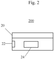
- Fig. 2 presents a side view of a parametrizable control pad 200 configured to control at least one building installation by a user according to an embodiment described herein.
- the control pad 200 has a capacitive area sensor 20.
- the capacitive area sensor 20 may span the entire surface of the control pad 200.
- the control pad 200 further has an interface unit 22.
- the interface unit 22 serves to receive input, such as a parametrization for the capacitive area sensor 20.
- a logic unit 24 of the control pad 200 serves to parametrize the capacitive area sensor 20 according to a received parametrization such that the capacitive area sensor 20 represents the one or more operation elements provided by the parametrization.
- the logic unit 24 also serves to convert a user input to the one or more operation function into a control signal for at least one building installation.
- Fig. 3 illustrates a schematic diagram of parametrizable control pad 300 according to a further embodiment.
- the control pad is presented in an exploded manner.
- the control pad 300 can have a technical cover 32 as an outer surface of the control pad 300.
- the technical cover 32 may be connected with the printable circuit board, PCBA, 34 which may carry the capacitive area sensor on one side, and a plurality of LED at the other side, the other side facing downward in this Fig.
- the technical cover 32 may be the interface of the control pad 300 to the environment.
- the capacitive area sensor may span the entire surface of the PCBA 34 which corresponds to the area of the control pad 300.
- a clamping arrangement 40 may be provided at the side of the sensor base 36 opposite to the side accommodating the PCBA 34.
- the clamping arrangement 40 may serve to fasten the control pad 300 at a flush-mounted insert (not shown) and may serve as an electro-mechanical interface in connection with the flush-mounted insert.
- the control pad 300 can be assembled by screws 42 and mounted, in its assembled form, to a flush-mounted insert.
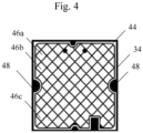
- Fig. 4 illustrates a schematic diagram of a top side of the PCB 34 according to an embodiment.
- This side of the PCBA 34 may carry the capacitive area sensor 44.
- the first top of the PCBA 34 may face towards a potential user or the environment.
- the capacitive area sensor 44 can have individual electrodes, which are arranged in a matrix.
- the electrodes are here exemplarily referred to as 46a, 46b, 46c.
- the number of individual electrodes may deviate from the one illustrated.
- the electrodes may be connected to a microcontroller which evaluates a user's touch and its position captured by the electrodes.
- Side recesses 48 can serve to assemble the PCB 34 within the control pad 300.
- the individual electrodes 46a, 46b, 46c may be grouped together to actuating fields (not shown).
- Fig. 5 illustrates a schematic diagram of a parametrization method 500 for a control pad according to an embodiment.
- the method 500 provides for receiving 50, by the user interface a parameterization for the capacitive area sensor, the parametrization comprising at least one operation function.
- the method 500 further provides for parametrizing 52, by the logic unit, the capacitive area sensor according to the parameterization such that the capacitive area sensor is configured to detect a user input to the at least one operation element and the logic unit is further configured to convert the user input to the at least one operation element into a control signal for the at least one building installation.
- Embodiments and/or features described herein with respect to the parametrization method may be implemented equally within the control pad and vice versa.
Landscapes
- Switches That Are Operated By Magnetic Or Electric Fields (AREA)
Priority Applications (1)
| Application Number | Priority Date | Filing Date | Title |
|---|---|---|---|
| EP22186968.8A EP4312372A1 (fr) | 2022-07-26 | 2022-07-26 | Tableau de commande paramétrable et procédé de paramétrage d'un tableau de commande pour des installations de bâtiment |
Applications Claiming Priority (1)
| Application Number | Priority Date | Filing Date | Title |
|---|---|---|---|
| EP22186968.8A EP4312372A1 (fr) | 2022-07-26 | 2022-07-26 | Tableau de commande paramétrable et procédé de paramétrage d'un tableau de commande pour des installations de bâtiment |
Publications (1)
| Publication Number | Publication Date |
|---|---|
| EP4312372A1 true EP4312372A1 (fr) | 2024-01-31 |
Family
ID=83115507
Family Applications (1)
| Application Number | Title | Priority Date | Filing Date |
|---|---|---|---|
| EP22186968.8A Pending EP4312372A1 (fr) | 2022-07-26 | 2022-07-26 | Tableau de commande paramétrable et procédé de paramétrage d'un tableau de commande pour des installations de bâtiment |
Country Status (1)
| Country | Link |
|---|---|
| EP (1) | EP4312372A1 (fr) |
Citations (2)
| Publication number | Priority date | Publication date | Assignee | Title |
|---|---|---|---|---|
| US6396007B1 (en) * | 1999-03-09 | 2002-05-28 | Merten Gmbh & Co. Kg | Installation switch for building installation |
| EP2665189A1 (fr) * | 2012-05-16 | 2013-11-20 | Comelit Group S.p.a. | Panneau bouton-poussoir pour contrôle capacitif pour série électrique résidentielle |
-
2022
- 2022-07-26 EP EP22186968.8A patent/EP4312372A1/fr active Pending
Patent Citations (2)
| Publication number | Priority date | Publication date | Assignee | Title |
|---|---|---|---|---|
| US6396007B1 (en) * | 1999-03-09 | 2002-05-28 | Merten Gmbh & Co. Kg | Installation switch for building installation |
| EP2665189A1 (fr) * | 2012-05-16 | 2013-11-20 | Comelit Group S.p.a. | Panneau bouton-poussoir pour contrôle capacitif pour série électrique résidentielle |
Similar Documents
| Publication | Publication Date | Title |
|---|---|---|
| US8476542B2 (en) | Input device | |
| US9696839B1 (en) | Vehicle door control | |
| KR100786429B1 (ko) | 3차원 포인팅 디바이스를 사용하는 무선식 입력 장치 및방법 | |
| US8723655B2 (en) | Remote control and method for the remote control of multimedia appliances | |
| US20160251880A1 (en) | Control for vehicle closures | |
| US20070247338A1 (en) | Remote control device | |
| CN114175508B (zh) | 具有电容式触摸表面的负载控制装置 | |
| KR101225973B1 (ko) | 전기전자기기의 정전 용량형 스위치 | |
| CA2694893C (fr) | Dispositif de telecommande | |
| EP3088641A1 (fr) | Commande pour fermetures de véhicule | |
| WO2011154930A1 (fr) | Organe de commande de tablette tactile | |
| JP2009110912A (ja) | 調光操作器及び調光システム | |
| JP5260241B2 (ja) | 車両アクセサリ用多連スイッチ | |
| EP4312372A1 (fr) | Tableau de commande paramétrable et procédé de paramétrage d'un tableau de commande pour des installations de bâtiment | |
| US20050126897A1 (en) | Reconfigurable switch | |
| CN102280020B (zh) | 触摸遥控器 | |
| EP4312371A1 (fr) | Élément de commande paramétrable assisté par l'éclairage et procédé de paramétrage d'un élément de commande assisté par l'éclairage pour des installations de construction | |
| US10409485B2 (en) | Adaptive user input device | |
| KR100872742B1 (ko) | 자동차용 파워 윈도우 스위치 모듈 | |
| EP4312373A1 (fr) | Élément de commande à éclairage, et procédé de commande à éclairage pour des installations de construction | |
| JP2000100287A (ja) | 操作パネル入力装置 | |
| JP4913534B2 (ja) | パワーウィンドウ開閉装置 | |
| US11444544B2 (en) | Converter | |
| US20040201572A1 (en) | Controlling device for mouse | |
| EP4226091A1 (fr) | Dispositif de cuisson doté d'un curseur tactile |
Legal Events
| Date | Code | Title | Description |
|---|---|---|---|
| PUAI | Public reference made under article 153(3) epc to a published international application that has entered the european phase |
Free format text: ORIGINAL CODE: 0009012 |
|
| STAA | Information on the status of an ep patent application or granted ep patent |
Free format text: STATUS: THE APPLICATION HAS BEEN PUBLISHED |
|
| AK | Designated contracting states |
Kind code of ref document: A1 Designated state(s): AL AT BE BG CH CY CZ DE DK EE ES FI FR GB GR HR HU IE IS IT LI LT LU LV MC MK MT NL NO PL PT RO RS SE SI SK SM TR |
|
| STAA | Information on the status of an ep patent application or granted ep patent |
Free format text: STATUS: REQUEST FOR EXAMINATION WAS MADE |
|
| 17P | Request for examination filed |
Effective date: 20240613 |
|
| RBV | Designated contracting states (corrected) |
Designated state(s): AL AT BE BG CH CY CZ DE DK EE ES FI FR GB GR HR HU IE IS IT LI LT LU LV MC MK MT NL NO PL PT RO RS SE SI SK SM TR |
|
| STAA | Information on the status of an ep patent application or granted ep patent |
Free format text: STATUS: EXAMINATION IS IN PROGRESS |
|
| 17Q | First examination report despatched |
Effective date: 20250313 |
|
| GRAP | Despatch of communication of intention to grant a patent |
Free format text: ORIGINAL CODE: EPIDOSNIGR1 |
|
| STAA | Information on the status of an ep patent application or granted ep patent |
Free format text: STATUS: GRANT OF PATENT IS INTENDED |
|
| INTG | Intention to grant announced |
Effective date: 20260218 |