EP2666450A2 - Fahrgestell für Krankentrage, das mit einem ausrückbaren Hubmechanismus ausgestattet ist - Google Patents
Fahrgestell für Krankentrage, das mit einem ausrückbaren Hubmechanismus ausgestattet ist Download PDFInfo
- Publication number
- EP2666450A2 EP2666450A2 EP13168411.0A EP13168411A EP2666450A2 EP 2666450 A2 EP2666450 A2 EP 2666450A2 EP 13168411 A EP13168411 A EP 13168411A EP 2666450 A2 EP2666450 A2 EP 2666450A2
- Authority
- EP
- European Patent Office
- Prior art keywords
- upper frame
- arm
- frame
- longitudinal
- trolley according
- Prior art date
- Legal status (The legal status is an assumption and is not a legal conclusion. Google has not performed a legal analysis and makes no representation as to the accuracy of the status listed.)
- Withdrawn
Links
- 239000011248 coating agent Substances 0.000 claims description 18
- 238000000576 coating method Methods 0.000 claims description 18
- 238000006073 displacement reaction Methods 0.000 abstract description 2
- 230000001681 protective effect Effects 0.000 description 2
- 230000014509 gene expression Effects 0.000 description 1
- 238000004519 manufacturing process Methods 0.000 description 1
Images

Classifications
-
- A—HUMAN NECESSITIES
- A61—MEDICAL OR VETERINARY SCIENCE; HYGIENE
- A61G—TRANSPORT, PERSONAL CONVEYANCES, OR ACCOMMODATION SPECIALLY ADAPTED FOR PATIENTS OR DISABLED PERSONS; OPERATING TABLES OR CHAIRS; CHAIRS FOR DENTISTRY; FUNERAL DEVICES
- A61G7/00—Beds specially adapted for nursing; Devices for lifting patients or disabled persons
- A61G7/002—Beds specially adapted for nursing; Devices for lifting patients or disabled persons having adjustable mattress frame
- A61G7/005—Beds specially adapted for nursing; Devices for lifting patients or disabled persons having adjustable mattress frame tiltable around transverse horizontal axis, e.g. for Trendelenburg position
-
- A—HUMAN NECESSITIES
- A61—MEDICAL OR VETERINARY SCIENCE; HYGIENE
- A61G—TRANSPORT, PERSONAL CONVEYANCES, OR ACCOMMODATION SPECIALLY ADAPTED FOR PATIENTS OR DISABLED PERSONS; OPERATING TABLES OR CHAIRS; CHAIRS FOR DENTISTRY; FUNERAL DEVICES
- A61G13/00—Operating tables; Auxiliary appliances therefor
- A61G13/02—Adjustable operating tables; Controls therefor
- A61G13/04—Adjustable operating tables; Controls therefor tiltable around transverse or longitudinal axis
Definitions
- the present invention relates to the field of patient transport trolleys that are usually found in hospitals, especially in emergency departments.
- This type of trolley is also called a stretcher trolley.
- the upper ends of the arms are generally pivotally mounted relative to the upper frame.
- the lifting arms are sometimes articulated in several points, which makes their realization quite complex.
- An object of the invention is to provide a transport trolley for a patient having an alternative to known height-adjustable trolleys.
- first and second lift arms are articulated only with respect to the lower and upper frame, and not in more ways like some existing solutions elsewhere. This facilitates the manufacture of the lift arms, but also to strengthen them, which improves the robustness of the truck.
- Both actuators allow the first and second lift arms to be pivoted independently of each other, which makes it easy to adjust the angle of inclination of the coating.
- the actuators are cylinders, pneumatic type.
- the upper frame comprises two longitudinal support members extending on either side of the coating, and the upper end of the first arm is pivotally mounted to each of the support elements.
- connection between the upper end of the first lifting arm and the upper frame is at two points.
- the upper end comprises a cross member extending perpendicularly to the first lifting arm and whose two ends are mounted in pivot connection relative to the upper frame.
- the upper end of the second arm cooperates only with one of the two longitudinal support members.
- connection between the upper end of the second lifting arm and the upper frame is at a single point.
- the second arm is mounted cantilever and takes back in one point the weight of the upper frame head.
- An advantage of this first embodiment is that, in the absence of a second connection point between the second lifting arm and the head side of the upper frame, the area below the head side of the upper frame is largely free, which makes it easy to place a medical device under the upper frame, or even allows the doctor to be easily and comfortably installed near the upper part of the patient's body.
- the upper end of the second arm is provided with an articulated shoe which is engaged in a guide rail fixed under the head side of the upper frame.
- a technical rail is used.
- the guide rail is fixed under one of the aforementioned longitudinal support elements.
- the upper end of the second arm is provided with a transverse bar which comprises a roller at each of its two ends, each of the longitudinal support elements comprises a slide disposed on the head side of the upper frame, and the rollers cooperate with the slideways to allow the sliding of the upper end of the second arm relative to the head side of the upper frame.
- connection between the upper end of the second lifting arm and the upper frame is at two points.
- An advantage of the second embodiment of the carriage with respect to the first is that it is less expensive in that it does not require a rail capable of supporting cantilever mounting.
- the lower frame has the shape of a "U" consisting of two transverse portions connected by a longitudinal portion, the pivot links of the first and second lifting arms being located in the longitudinal portion, while the ends of the transverse portions carry the wheels of the carriage.
- the lifting arms are offset on a lateral edge of the carriage to clear a space under the upper frame, whereby the stretcher trolley according to the invention can be brought under a radiology equipment, such as an amplifier. shine, or any other medical device requiring access to an area under the patient lying down. These devices most often have an arc portion whose ends are placed above and below the coating.
- a radiology equipment such as an amplifier. shine, or any other medical device requiring access to an area under the patient lying down.
- These devices most often have an arc portion whose ends are placed above and below the coating.
- the "U" shape of the lower frame also facilitates the positioning of the carriage under such an apparatus, insofar as the lower portion of the arc portion of the image intensifier can be housed between the two transverse portions of the lower frame. It is understood in particular that the lift arms, offset on one side of the carriage, do not interfere with the positioning of the carriage under the radiology apparatus.
- the upper end of the second arm cooperates only with the longitudinal support member which is arranged on the side of the longitudinal portion, which allows to release even more space under the upper frame.
- the bodies of the actuators are fixed in the central part of the longitudinal portion, while their rods extend towards the transverse portions.
- the actuators in this case the two cylinders, so are mounted back to back.
- This arrangement has the advantage of being compact, the actuators also being offset on a side edge of the carriage.
- the actuators are fixed below the longitudinal portion.
- first and second lift arms have curved portions in the form of a "C" facing the longitudinal ends of the carriage.
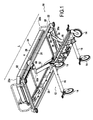
- FIG. 1 there is shown in perspective a first embodiment of a transport carriage 10 for a patient.
- This type of trolley also called stretcher trolley, is mainly intended for use in hospitals, especially in emergency departments.
- the transport carriage 10 comprises a lower frame 12 provided with four wheels 14 for moving the carriage.
- the lower frame 12 considered in a horizontal plane, has the shape of a "U" consisting of two transverse portions 16 interconnected by a longitudinal portion 18.
- the frame of the lower frame 12 may be covered with a protective housing 20 which also has the shape of a "U".
- the four wheels 14 of the carriage 10 are fixed at the ends of the transverse portions 16 and the transverse portion 18 so that the attachment points of the wheels 14 are located on the vertices of a rectangle. It is also specified that, in this example, the transverse portions 16 are perpendicular to the longitudinal portion 18.
- the transport carriage 10 further comprises an upper frame 22 comprising a coating 24 which is constituted here of a mattress 26.
- the upper frame 22 consists of a rectangular frame 28 which is provided with two longitudinal elements 29, 31, the first and second longitudinal members 30, 32 being parallel and remote.
- the upper frame 22 has a head 22a and a foot 22b side .
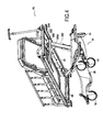
- the part of the coating which is located on the head side 22a can pivot relative to the rest of the coating as can be understood by referring to the figure 4 .
- the upper frame 22, and more precisely the frame 28, is connected to the lower frame 12 via a first lifting arm 30 and a second lifting arm 32 which allow the displacement of the upper frame 22 relative to the lower frame 12.
- the first lifting arm 30 is pivotally mounted to the longitudinal portion 18 about a pivot axis A which is perpendicular to the longitudinal direction L of the coating.
- the second lifting arm 32 is pivotally mounted to the longitudinal portion 18 about a pivot axis B, the latter also being perpendicular to the longitudinal direction L of the coating.
- the axes of rotation A and B are distinct.
- the first and second lifting arms 30, 32 are symmetrical with respect to each other with respect to a vertical plane perpendicular to the longitudinal direction L of the coating.
- the first lift arm 30 has a first beam 34 attached to a first arcuate portion 36, while the second lift arm 32 includes a second beam 38 integrally attached to a second arcuate portion 40.
- the first and second arcuate portions 36, 40 have the shape of a "C" facing the outside of the carriage.
- first and second arcuate portions 36, 40 which are pivotally attached to the longitudinal portion 18.
- the upper end 30a of the first lifting arm 30 constituted by the upper end 34a of the first beam is pivotally mounted to the foot side 22b of the upper frame 22.
- This first actuator 52 is a pneumatic cylinder having a body 54 pivotally attached to a plate 56 which is itself secured to the longitudinal portion 18.
- the axis of pivoting between the first lifting arm 30 and the first actuator 52, as well as the pivot axis D of the body 54 of the first actuator 52 relative to the lower frame 12 are parallel to each other and perpendicular to the longitudinal direction L of the bedding.
- the axis of rotation E of the first lifting arm 30 relative to the upper frame 22 is also perpendicular to the longitudinal direction L of the coating plane.
- the first lifting arm 30 is actuated by the first actuator 52. More specifically, actuation of the first actuator 52 in a direction where the rod 50 is retracted into the body 54 causes the descent of the foot side 22b of the upper frame 22 while the deployment of the rod 50 out of the body 54 causes the lifting of the foot side 22b of the upper frame 22.
- axis of rotation E of the first lifting arm relative to the upper frame 22 and the pivot axis D of the first actuator 52 relative to the lower frame are arranged on either side of a vertical plane. passing through the pivot axis of the first lifting arm 30 relative to the lower frame.
- the upper end of the first arm 30a is pivotally mounted to each of the support members 29, 31 of the upper frame.
- the upper end 30a of the first lifting arm 30 comprises a first cross member 60 secured integrally to the upper end of the first beam 34, the ends 60a and 60b of this first cross member being pivotally mounted to the two elements of longitudinal support 29, 31.
- the upper end 30a of the first lifting arm 30 is fixed near the end 60a of the first cross member 60 so that the first lifting arm 30 is offset relative to the upper frame 22 on the side of the longitudinal portion 18.
- the lower end 32b of the second lifting arm 32 consisting of the lower end 40a of the second arcuate portion 40 is pivotally attached about an axis F at the end of a rod 70 a second actuator 72.
- This second actuator 72 comprises a body 74 which is pivotally mounted about a pivot axis G with respect to the aforementioned plate 56 .
- first and second pneumatic cylinders are positioned symmetrically with respect to a vertical plane perpendicular to the longitudinal direction L of the coating.
- the second lift arm 32 has an upper end 32a which is slidably and pivotally mounted relative to the head side 22a of the upper frame 22.
- the upper end 32a of the second arm 32 cooperates only with one of the two elements of longitudinal support. This is clearly visible on the figure 1 .
- the upper end 32a of the second arm 32 is provided with a shoe 80 which is pivotally mounted relative to the upper end 32a of the second lifting arm about a pivot axis H, this shoe 80 being engaged with a guide rail 82 which is fixed under the head side 22a of the upper frame 22.
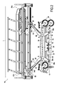
- the first and second actuators 52, 72 are actuated so as to pivot the first and second lifting arms in a direction in which the upper ends of the first and second are lowered. lifting arm.
- this movement is achieved by retracting the rods 50, 70. This causes the relative distance of the upper ends 30a and 32a of the first and second lifting arms. Since the upper end 30a of the first lifting arm is fixed relative to the upper frame, it is understood that, in the downward movement, the shoe 80 slides along the guide rail 82 so as to move away from the end upper 30a of the first lifting arm 30; in other words, the shoe 80 is close to the longitudinal end of the upper frame 22 disposed on the head side 22a.
- the arm mounted to slide and pivot relative to the upper frame could be arranged on the foot side 22b. This amounts to reversing the first and second lift arms of the figure 2 .
- the carriage according to the second embodiment is similar to the first embodiment. However, it is distinguished by the structure of the second lifting arm 320. As can be seen in this figure, the upper end 320a of the second lifting arm 320 is integrally fixed to a second cross member 322 which extends perpendicular to the second lifting arm 320. The longitudinal ends of this second cross member 322 are provided with rollers 324 which cooperate with slides 326 and 328 which are mounted below the support members 29, 31 of the head side of the upper frame 22. . in this second embodiment, the upper end 320a of the second lift arm 320 is again slidably and pivotally mounted relative to the head side of the upper frame. It is understood that the rollers 324, which cooperate with the slides 326, 328 allow the sliding of the upper end 320a of the second arm 320 relative to the head side of the upper frame.
- first and second lift arms are connected at four points to the upper frame.
Landscapes
- Health & Medical Sciences (AREA)
- Rehabilitation Therapy (AREA)
- Nursing (AREA)
- Life Sciences & Earth Sciences (AREA)
- Animal Behavior & Ethology (AREA)
- General Health & Medical Sciences (AREA)
- Public Health (AREA)
- Veterinary Medicine (AREA)
- Invalid Beds And Related Equipment (AREA)
Applications Claiming Priority (1)
| Application Number | Priority Date | Filing Date | Title |
|---|---|---|---|
| FR1254647A FR2990849B1 (fr) | 2012-05-22 | 2012-05-22 | Chariot de brancard muni d'un mecanisme de levee deporte |
Publications (2)
| Publication Number | Publication Date |
|---|---|
| EP2666450A2 true EP2666450A2 (de) | 2013-11-27 |
| EP2666450A3 EP2666450A3 (de) | 2015-01-07 |
Family
ID=48407415
Family Applications (1)
| Application Number | Title | Priority Date | Filing Date |
|---|---|---|---|
| EP13168411.0A Withdrawn EP2666450A3 (de) | 2012-05-22 | 2013-05-20 | Fahrgestell für Krankentrage, das mit einem ausrückbaren Hubmechanismus ausgestattet ist |
Country Status (2)
| Country | Link |
|---|---|
| EP (1) | EP2666450A3 (de) |
| FR (1) | FR2990849B1 (de) |
Cited By (3)
| Publication number | Priority date | Publication date | Assignee | Title |
|---|---|---|---|---|
| CN106511021A (zh) * | 2016-12-05 | 2017-03-22 | 苏州科技城医院 | 急救床 |
| CN108852407A (zh) * | 2018-04-27 | 2018-11-23 | 郑善水 | 一种使用方便的超声科室用诊疗床 |
| AU2020210222B2 (en) * | 2019-08-01 | 2025-04-03 | Modsel Pty Ltd | Patient support suitable for X-ray |
Citations (1)
| Publication number | Priority date | Publication date | Assignee | Title |
|---|---|---|---|---|
| US6574493B2 (en) | 2000-02-26 | 2003-06-03 | Koninklijke Philips Electronics N.V. | Method of localizing objects in interventional radiology |
Family Cites Families (5)
| Publication number | Priority date | Publication date | Assignee | Title |
|---|---|---|---|---|
| GB1352764A (en) * | 1971-08-24 | 1974-05-08 | Rubery Owen & Co Ltd | Support for movable platform |
| US5074000A (en) * | 1991-01-11 | 1991-12-24 | Ssi Medical Services, Inc. | Apparatus for performing head and foot Trendelenburg therapy |
| DE4317208C1 (de) * | 1993-05-22 | 1994-06-30 | Arnold L & C | Krankenbett |
| WO2001074286A1 (en) * | 2000-04-04 | 2001-10-11 | Huntleigh Technology Plc | Patient support |
| US7150056B2 (en) * | 2004-07-29 | 2006-12-19 | Stryker Corporation | Patient support deck lifting/lowering assembly |
-
2012
- 2012-05-22 FR FR1254647A patent/FR2990849B1/fr active Active
-
2013
- 2013-05-20 EP EP13168411.0A patent/EP2666450A3/de not_active Withdrawn
Patent Citations (1)
| Publication number | Priority date | Publication date | Assignee | Title |
|---|---|---|---|---|
| US6574493B2 (en) | 2000-02-26 | 2003-06-03 | Koninklijke Philips Electronics N.V. | Method of localizing objects in interventional radiology |
Cited By (3)
| Publication number | Priority date | Publication date | Assignee | Title |
|---|---|---|---|---|
| CN106511021A (zh) * | 2016-12-05 | 2017-03-22 | 苏州科技城医院 | 急救床 |
| CN108852407A (zh) * | 2018-04-27 | 2018-11-23 | 郑善水 | 一种使用方便的超声科室用诊疗床 |
| AU2020210222B2 (en) * | 2019-08-01 | 2025-04-03 | Modsel Pty Ltd | Patient support suitable for X-ray |
Also Published As
| Publication number | Publication date |
|---|---|
| FR2990849A1 (fr) | 2013-11-29 |
| FR2990849B1 (fr) | 2014-06-20 |
| EP2666450A3 (de) | 2015-01-07 |
Similar Documents
| Publication | Publication Date | Title |
|---|---|---|
| BE488667A (de) | ||
| CN101400330A (zh) | 具有改进的活动框架的救护车担架床 | |
| FR2934773A1 (fr) | Lit de malade a barriere laterale facilitant la levee du patient. | |
| FR2735019A1 (fr) | Element mobile, en particulier lit d'hospitalisation, prenant appui sur le sol par plusieurs roues de sustentation orientables | |
| EP3247610B1 (de) | Wagen zum transportieren oder parken eines fahrrades | |
| EP0365455B1 (de) | Transportvorrichtung für Patienten | |
| FR2990849A1 (fr) | Chariot de brancard muni d'un mecanisme de levee deporte | |
| EP1245212B1 (de) | Fahrgerät für eine Krankentrage | |
| EP2020976B1 (de) | Stehhilfe für personen | |
| EP4456852B1 (de) | Teleskopisch neigbare fussstütze für einen motorisierten rollstuhl | |
| FR2941368A1 (fr) | Sommier avec dispositif proclive pour un lit | |
| CA3018671A1 (fr) | Lit medicalise | |
| EP4474334A1 (de) | Fahrzeughebevorrichtung | |
| EP3070203A1 (de) | Be-, entlade- und aufsetzsystem eines gleisgeräts auf ein bahngleis | |
| EP1053705A1 (de) | Krankenhausbett mit Seitenlehne | |
| WO2008029357A2 (fr) | Dispositif pour lever et transferer des corps | |
| FR2990848A1 (fr) | Chariot de brancard muni de barrieres indexees multipositions | |
| WO2017174543A1 (fr) | Structure de lit relevable à support d'assise escamotable | |
| EP4551445A1 (de) | Transportwagen mit aufgehängten rollen und mit einem immobilisierungskissen | |
| CH705989B1 (fr) | Dispositif de guidage et de levage de garde-corps de plateforme de travail en encorbellement. | |
| EP0226682B1 (de) | Fahrgestell für den Krankentransport | |
| FR3026176A1 (fr) | Regle de mesure sur voie de chemin de fer | |
| EP1693276B1 (de) | Zusammenklappbarer Kinderwagen mit einer drehbaren Fussstütze | |
| EP2127973B1 (de) | Rollbettbremssystem | |
| WO2020128308A1 (fr) | Conteneur équipé d'un système de reploiement/déploiement d'une bache, le système en lui-même et le procédé de reploiement/deploiement d'une bache sur un conteneur |
Legal Events
| Date | Code | Title | Description |
|---|---|---|---|
| PUAI | Public reference made under article 153(3) epc to a published international application that has entered the european phase |
Free format text: ORIGINAL CODE: 0009012 |
|
| AK | Designated contracting states |
Kind code of ref document: A2 Designated state(s): AL AT BE BG CH CY CZ DE DK EE ES FI FR GB GR HR HU IE IS IT LI LT LU LV MC MK MT NL NO PL PT RO RS SE SI SK SM TR |
|
| AX | Request for extension of the european patent |
Extension state: BA ME |
|
| PUAL | Search report despatched |
Free format text: ORIGINAL CODE: 0009013 |
|
| AK | Designated contracting states |
Kind code of ref document: A3 Designated state(s): AL AT BE BG CH CY CZ DE DK EE ES FI FR GB GR HR HU IE IS IT LI LT LU LV MC MK MT NL NO PL PT RO RS SE SI SK SM TR |
|
| AX | Request for extension of the european patent |
Extension state: BA ME |
|
| RIC1 | Information provided on ipc code assigned before grant |
Ipc: A61G 13/04 20060101ALI20141202BHEP Ipc: A61G 7/005 20060101AFI20141202BHEP |
|
| STAA | Information on the status of an ep patent application or granted ep patent |
Free format text: STATUS: THE APPLICATION IS DEEMED TO BE WITHDRAWN |
|
| 18D | Application deemed to be withdrawn |
Effective date: 20150708 |