EP2666925B1 - Verbundstruktur eines isolierten Paneels und Belagblech mit entsprechenden Befestigungsmitteln zur Anwendung in Baukonstruktionen - Google Patents
Verbundstruktur eines isolierten Paneels und Belagblech mit entsprechenden Befestigungsmitteln zur Anwendung in Baukonstruktionen Download PDFInfo
- Publication number
- EP2666925B1 EP2666925B1 EP13168645.3A EP13168645A EP2666925B1 EP 2666925 B1 EP2666925 B1 EP 2666925B1 EP 13168645 A EP13168645 A EP 13168645A EP 2666925 B1 EP2666925 B1 EP 2666925B1
- Authority
- EP
- European Patent Office
- Prior art keywords
- attaching means
- panel
- metal sheet
- fastening
- insulated panel
- Prior art date
- Legal status (The legal status is an assumption and is not a legal conclusion. Google has not performed a legal analysis and makes no representation as to the accuracy of the status listed.)
- Not-in-force
Links
- 239000002184 metal Substances 0.000 title claims description 68
- 239000002131 composite material Substances 0.000 title description 5
- 238000004873 anchoring Methods 0.000 claims description 8
- 230000008878 coupling Effects 0.000 description 7
- 238000010168 coupling process Methods 0.000 description 7
- 238000005859 coupling reaction Methods 0.000 description 7
- 239000000463 material Substances 0.000 description 5
- 238000009434 installation Methods 0.000 description 4
- 239000011810 insulating material Substances 0.000 description 4
- 238000004519 manufacturing process Methods 0.000 description 3
- 229920002635 polyurethane Polymers 0.000 description 3
- 239000004814 polyurethane Substances 0.000 description 3
- 238000004513 sizing Methods 0.000 description 3
- XLYOFNOQVPJJNP-UHFFFAOYSA-N water Substances O XLYOFNOQVPJJNP-UHFFFAOYSA-N 0.000 description 3
- 241000397426 Centroberyx lineatus Species 0.000 description 2
- 238000003780 insertion Methods 0.000 description 2
- 230000037431 insertion Effects 0.000 description 2
- 239000004952 Polyamide Substances 0.000 description 1
- 230000000295 complement effect Effects 0.000 description 1
- 238000010276 construction Methods 0.000 description 1
- 230000001419 dependent effect Effects 0.000 description 1
- 239000006260 foam Substances 0.000 description 1
- 238000005187 foaming Methods 0.000 description 1
- 239000012212 insulator Substances 0.000 description 1
- 238000003475 lamination Methods 0.000 description 1
- 238000000034 method Methods 0.000 description 1
- 239000004033 plastic Substances 0.000 description 1
- 229920003023 plastic Polymers 0.000 description 1
- 229920002647 polyamide Polymers 0.000 description 1
- 230000000630 rising effect Effects 0.000 description 1
- 125000006850 spacer group Chemical group 0.000 description 1
- 238000009423 ventilation Methods 0.000 description 1
Images





Classifications
-
- E—FIXED CONSTRUCTIONS
- E04—BUILDING
- E04D—ROOF COVERINGS; SKY-LIGHTS; GUTTERS; ROOF-WORKING TOOLS
- E04D3/00—Roof covering by making use of flat or curved slabs or stiff sheets
- E04D3/35—Roofing slabs or stiff sheets comprising two or more layers, e.g. for insulation
- E04D3/351—Roofing slabs or stiff sheets comprising two or more layers, e.g. for insulation at least one of the layers being composed of insulating material, e.g. fibre or foam material
- E04D3/352—Roofing slabs or stiff sheets comprising two or more layers, e.g. for insulation at least one of the layers being composed of insulating material, e.g. fibre or foam material at least one insulating layer being located between non-insulating layers, e.g. double skin slabs or sheets
-
- F—MECHANICAL ENGINEERING; LIGHTING; HEATING; WEAPONS; BLASTING
- F24—HEATING; RANGES; VENTILATING
- F24S—SOLAR HEAT COLLECTORS; SOLAR HEAT SYSTEMS
- F24S25/00—Arrangement of stationary mountings or supports for solar heat collector modules
- F24S25/60—Fixation means, e.g. fasteners, specially adapted for supporting solar heat collector modules
- F24S25/61—Fixation means, e.g. fasteners, specially adapted for supporting solar heat collector modules for fixing to the ground or to building structures
- F24S25/615—Fixation means, e.g. fasteners, specially adapted for supporting solar heat collector modules for fixing to the ground or to building structures for fixing to protruding parts of buildings, e.g. to corrugations or to standing seams
-
- F—MECHANICAL ENGINEERING; LIGHTING; HEATING; WEAPONS; BLASTING
- F24—HEATING; RANGES; VENTILATING
- F24S—SOLAR HEAT COLLECTORS; SOLAR HEAT SYSTEMS
- F24S25/00—Arrangement of stationary mountings or supports for solar heat collector modules
- F24S25/60—Fixation means, e.g. fasteners, specially adapted for supporting solar heat collector modules
- F24S25/63—Fixation means, e.g. fasteners, specially adapted for supporting solar heat collector modules for fixing modules or their peripheral frames to supporting elements
-
- F—MECHANICAL ENGINEERING; LIGHTING; HEATING; WEAPONS; BLASTING
- F24—HEATING; RANGES; VENTILATING
- F24S—SOLAR HEAT COLLECTORS; SOLAR HEAT SYSTEMS
- F24S25/00—Arrangement of stationary mountings or supports for solar heat collector modules
- F24S25/60—Fixation means, e.g. fasteners, specially adapted for supporting solar heat collector modules
- F24S2025/6004—Fixation means, e.g. fasteners, specially adapted for supporting solar heat collector modules by clipping, e.g. by using snap connectors
-
- Y—GENERAL TAGGING OF NEW TECHNOLOGICAL DEVELOPMENTS; GENERAL TAGGING OF CROSS-SECTIONAL TECHNOLOGIES SPANNING OVER SEVERAL SECTIONS OF THE IPC; TECHNICAL SUBJECTS COVERED BY FORMER USPC CROSS-REFERENCE ART COLLECTIONS [XRACs] AND DIGESTS
- Y02—TECHNOLOGIES OR APPLICATIONS FOR MITIGATION OR ADAPTATION AGAINST CLIMATE CHANGE
- Y02B—CLIMATE CHANGE MITIGATION TECHNOLOGIES RELATED TO BUILDINGS, e.g. HOUSING, HOUSE APPLIANCES OR RELATED END-USER APPLICATIONS
- Y02B10/00—Integration of renewable energy sources in buildings
- Y02B10/20—Solar thermal
-
- Y—GENERAL TAGGING OF NEW TECHNOLOGICAL DEVELOPMENTS; GENERAL TAGGING OF CROSS-SECTIONAL TECHNOLOGIES SPANNING OVER SEVERAL SECTIONS OF THE IPC; TECHNICAL SUBJECTS COVERED BY FORMER USPC CROSS-REFERENCE ART COLLECTIONS [XRACs] AND DIGESTS
- Y02—TECHNOLOGIES OR APPLICATIONS FOR MITIGATION OR ADAPTATION AGAINST CLIMATE CHANGE
- Y02E—REDUCTION OF GREENHOUSE GAS [GHG] EMISSIONS, RELATED TO ENERGY GENERATION, TRANSMISSION OR DISTRIBUTION
- Y02E10/00—Energy generation through renewable energy sources
- Y02E10/40—Solar thermal energy, e.g. solar towers
- Y02E10/47—Mountings or tracking
Definitions
- the present invention relates to an improved structure of an insulated panel and corresponding covering structure, in particular for use in the building industry.
- Insulating panels for use in the building industry, in particular for the covering of roofs, are well-known in the art. These conventional panels typically consist of two outer sheets, made of metal or PVC, between which a pane of foamed polyurethane is inserted. Depending on the overall size, on the material used and on the thickness of the outer sheets, the insulating panels may also be self-supporting.
- insulating panel consists of the "panels for covering" from Isopan SpA's catalogue.
- WO2004/009929 illustrates a panel consisting of a pair of metal sheets, one of which decorated with corrugated ornamental motives, coupled sandwich-like with an intermediate insulating layer. More precisely, the lower metal sheet is essentially flat, while the upper metal sheet is shaped so as to form longitudinal ribbings; these have primarily a stiffening function, but at the same time they admit the use of fastening means, in particular screws, for anchoring to the below-lying panel-supporting structure.
- WO96/35028 Another known insulated panel is the one illustrated in WO96/35028 .
- This too is a panel consisting of a pair of metal sheets between which an insulating layer is arranged sandwich-like; the fastening means are again anchoring means of the panels to a supporting structure.
- Panel fastening occurs again by means of through-screws, however, the through-holes are provided only along a first edge of the panel: on the edge on the opposite side a different folding of the metal sheet is instead provided which forms a coupling and protection lip.
- the terminal lip has the function of engaging with the first edge of the adjacent panel with two different purposes: on the one hand, overlapping the first edge, it protects the holes of the anchoring screws, so as to inhibit water entry and, on the other hand, it engages with an undercut profile determining a stable coupling between two adjacent panels.
- an insulated panel of the type mentioned above is also known, mainly meant for the mounting in a vertical wall.
- This panel has a series of longitudinal ribbings with a substantially swallow-tail-shaped section: support clamps cooperate with these.
- a structure of this type - provided for the mounting of the panels in a vertical position, where moreover the phenomenon of water seepage is little relevant - has some drawbacks.
- the swallow-tail shape of the ribbings is highly stressful for the material, which must hence remain of a small thickness; in order to then have the desired stiffness, the system provides the insertion of complex and expensive stiffening frames into the panel.
- the clamps having a shape complementary to the swallow tail, are obtained integrally and must be slipped on and made to slide along the ribbing until bringing them in the desired position: it is hence necessary to have free access to the terminal end of the panel, which is not always possible, especially after having mounted the panel on the building.
- DE-102007036206 and DE-102007036208 relate again to an insulated panel of the type mentioned above, that is, consisting of a pair of corrugated metal sheets arranged sandwich-like with an insulating layer.
- the corrugated metal sheet has longitudinal ribbings shaped with a first root portion at the end of which a head is defined with a pair of opposite undercut planes.
- This configuration is relatively easier to obtain with respect to the one indicated above and allows the use of open clamps (which hence do not require the insertion from the terminal end of the panel).
- clamps providing at least a moving part: this component allows the opening of the clamp and is then pushed against the undercut plane by tightening means.
- the problem at the basis of the invention is to propose a combined structure of an insulated panel, of the general type described above consisting of a pair of metal sheets arranged sandwich-like with an insulating layer, and of relative attaching means of a covering metal sheet, which overcomes the mentioned drawbacks of the prior art.
- an insulated panel P is manufactured, according to a technique well-known per se, as a prefabricated, composite structure, consisting of two metal sheets 1, 2 (for example, conventional thicknesses between 0.4 mm and 1.0 mm), between which a pane 3 of foamed, insulating material is arranged, for example of polyurethane of a thickness ranging between 40 mm and 120 mm.
- metal sheet 1 with a virtually flat profile
- metal sheet 2 as a corrugated metal sheet
- corrugated metal sheet 2 has ribbings 4 at regular intervals, which ribbings are generally both stiffening elements and anchoring and/or support elements.
- ribbings have a section profile provided with a root portion, rising from the flat part of the metal sheet, which defines a retaining head at the distal end of said root portion.
- the profile of the corrugated metal sheet is more specifically as clearly illustrated in fig. 2 and it is apt to engage with attaching means meant to be snap-coupled, as will be better illustrated below.
- the profile of the ribbing 4 of the metal sheet has a root portion 4a, with walls converging outwards (of the panel) in the shape of equilateral trapetium, which ends in a distal, mushroom-shaped head portion 5.
- the metal sheet is folded a first time diverging outwards and slightly backwards, forming a small undercut fold, and then a second time converging inwards with an inclination of the same order of magnitude, but slightly smaller, as the sides of root portion 4a.
- the converging sides of terminal head 5 do not intercept each other, because they end in a connection side 5a substantially parallel to the panel plane.
- the section shape of the ribbing is a geometric shape given by two equilateral trapetiums one above the other, the bottom one having a major base and with the slanting sides more converging than the top one. Between the two trapezoidal figures an S-shaped fold is provided which forms two deep loops, an outer undercut groove 6 (internally forming a projecting rib) and an inner undercat recess 6a.
- At least corrugated metal sheet 2 preferably has a thickness, for example, of 0.6 mm, hence such as to be sufficiently rigid, but at the same time to allow (during manufacturing) a folding of the metal sheet apt to form the ribbings 4 of the described shape.
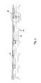
- Fig. 3 shows a combined structure according to an embodiment of the invention.
- attaching means are provided - to which a finish/covering metal sheet may then be fastened, such as the known metal sheet manufactured and marketed under the trademark RIVERCLACK ® - which may be constrained to the panel from the inner side of corrugated metal sheet 2, hence giving the opportunity to connect the equipment in the shape of metal sheet on the side opposite to that of ribbings 4.
- the attaching means is configured to penetrate into the thickness of panel P, carving flat metal sheet 1, ending up engaging by means of respective hooked ends with the grooves 6a from the inner side.
- the attaching means are substantially in the shape of a fork with two parallel hooked arms, which depart from a rigid box-like base and may be elastically moved closer together.
- the parallel arms end with hook means, suited to snap engage with the inner undercut recesses 6a defined on the inner side of ribbing 4.
- the length of the arms is sufficient to run through the entire thickness of insulated panel P, snap-engaging with recesses 6a and bringing the rigid box-like base in the proximity of or adjacent to the outer side of flat metal sheet 1.
- panel P is mounted horizontally with the corrugated metal sheet facing downwards, with the attaching systems on the flat side of panel P, i.e. on the top side.
- the rigid box-like body 25 of the attaching means is configured in an original manner to be able to fasten thereto various technical accessories, possibly with the help of crossbars.
- box-like body 25 consists of a main portion 25a, for example parallelepiped-shaped, comprised between two flat flange plates 25b and 25c which have a wider perimeter profile than the main portion.
- the two flat flange plates 25b and 25c determine pairs of lateral rails (along the perimeter sides) with which some other fastening accessory may be slidably coupled.
- the main body and flanges are preferably of a square or rectangular shape (i.e. with opposite parallel sides)
- Elements 25, 26 and 27 are preferably made of plastic material, for example glass-fiber-reinforced polyamide.
- a typical accessory consists of a slider body 27 which acts as a clamp for the snap-fastening of the fastening edges 28 of a covering metal sheet F 1 , for example the known metal sheets marketed by Iscom SpA under the trademark RI-VERCLACK ® , possibly in the version equipped with photovoltaic cells.
- a covering metal sheet F 1 for example the known metal sheets marketed by Iscom SpA under the trademark RI-VERCLACK ® , possibly in the version equipped with photovoltaic cells.
- clamp 27 Further details on the specific configuration of clamp 27 are not supplied here, being well-known to a person skilled in the field as well as being described, for example, in WO2006117605 and WO2011007201 .
- attaching means 25, 26 and 27 are arranged in rows, in the desired number, in correspondence (but on the opposite side) of ribbings 4, applied on the side of flat metal sheet 1 (i.e. on the side opposite to the corrugated metal sheet which determines ribbings 4).
- the distance between the individual rows of attaching means is univocally determined by the pitch between ribbings 4.
- a pair of notches 100 or a continuous hole of the same size is practised in top flat metal sheet 1, so as to insert flexible arms 26.
- the sizing of arms 26 and of corresponding hooks 26a is such as to be able to perforate the insulating material (typically foamed polyurethane) of the panel without problems.
- panel P is preferably built so that the insulating material does not obstruct the inner channel defined by the perimeter side of ribbing 4, or at least the head end portion 5 of ribbing 4. That helps a perfect coupling of hooks 26a within recesses 6a, eliminating any risk that the attaching means may come off the panel.
- a tool to be inserted along flexible arms 26 and to wedge itself between the hook and the respective recesses can be used for example.
- a thin sheet of easily breakable material for example paper
- a thin sheet of easily breakable material for example paper
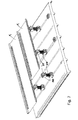
- Fig. 5 shows an embodiment of the structure, wherein covering metal sheet F 1 is arranged with its longitudinal axis in a crosswise direction to ribbing lines 4; clamps 27 are directly mounted on the bodies 25 of the attaching means: the pitch of ribbings 4 is irrelevant for the setting of metal sheets F 1 .
- fig. 6 shows a variant in which the covering metal sheets are arranged aligned with ribbing lines 4.
- the width of the metal sheets does not match the pitch of the ribbings 4 of the corrugated metal sheet of panel P, attaching clamps 27 are fastened to crossbars 27a.
- Crossbars 27a have a C-shaped profile suited to slidably engage with fastening bodies 25, in a crosswise direction to the axes of ribbings 4: thereby, the pitch of the ribbings does not affect the installation, because clamps 27 are fastened to the crossbars with the desired pitch compatible with those of metal sheets F 1 .
- Fig. 7 shows a further embodiment, similar to that of fig. 5 .
- clamps 27 are fastened to the upper end of a spacing column 29, in turn connected to a pair of coupling heads 30.
- a spacing column preferably consists of a rigid cylindrical element provided with an outer threading, coupled at the two ends with respective identical head elements 30' and 30".
- Each head element 30 is in the shape of a rigid box-like body, which has a central hole meant for the screwing on cylindrical element 29 and is provided below and on top with respective female and male engaging elements for the coupling with other elements 29, so as to allow a certain modularity in height.
- box-like bodies 30 have female engaging elements 30a and male engaging elements 30b similar to those provided on fastening body 25 of the embodiment of fig. 5 , i.e. with slider engagement, to have an advantageous compatibility and modularity.
- Lower head 30' is then mounted on fastening body 25, while upper head 30" engages with a clamp 27 meant in turn to couple with covering metal sheets F 1 .
- the presence of column 29 allows to remarkably space apart metal sheets F 1 from insulated panel P and hence to define a gap chamber or compartment in which to install other typical elements for coverings, such as vapour, heat or acoustic insulators, or to determine good ventilation or the passage of other technical plants. Due to the fact that the attaching surface of the panel is substantially flat, the gap compartment is large and free from obstacles. Moreover through the modularity and fine adjustment (by means of screwing/unscrewing along threaded column 29) determined by the coupling of elements 29, 30' and 30", it is possible to create the desired slopes between the panels and the covering metal sheet.
- Fig. 8 shows another variant equivalent to that illustrated in fig. 6 , wherein the clamps 27 of covering plates F 1 are fastened to crossbars 31 in turn engaged with the upper heads 30" of a series of spacing elements 29 (illustrated in greater detail in fig. 10 ).
- the combined structure according to the invention perfectly achieves the objects set forth in the premises.
- the combination of the panel with the specific corrugated metal sheet and the respective attaching means provides an extremely flexible composite structure easy to set working.
- the attaching means may be fastened from the flat side of the panel, despite being able to attach securely, by simple deformation and snap engagement, to the ribbing of the corrugated metal sheet: a gap compartment free from dividing obstacles can hence be obtained.
- the ribbings on the lower side in addition to allowing a good fastening of the attaching means, contribute to the stiffening of the insulating panel.
- the original configuration of the attaching means allows to achieve good installation flexibility, without special constraints on the pitch of the covering metal sheets and being able to determine the correct roof slope in those situations in which it is not possible to obtain it through the simple setting of a single covering element.
- the panels according to the invention have widths (measured in a direction orthogonal to the ribbings of the corrugated metal sheet) compatible with the production processes and with transport economies, but can be securely coupled with each other - defining a continuous covering - in different ways which are not specifically dealt with in the present invention.
- fastening box-like bodies 25 or of spacing columns 29 is to be considered as a preferred embodiment: other numerous variants may be conceived by the person skilled in the field, for example with bayonet coupling.
Landscapes
- Engineering & Computer Science (AREA)
- Chemical & Material Sciences (AREA)
- Thermal Sciences (AREA)
- General Engineering & Computer Science (AREA)
- Physics & Mathematics (AREA)
- Life Sciences & Earth Sciences (AREA)
- Sustainable Development (AREA)
- Sustainable Energy (AREA)
- Mechanical Engineering (AREA)
- Combustion & Propulsion (AREA)
- Architecture (AREA)
- Civil Engineering (AREA)
- Structural Engineering (AREA)
- Laminated Bodies (AREA)
- Building Environments (AREA)
Claims (7)
- Verbundstruktur eines isolierten Paneels (P), bestehend aus einem Paar Metallbleche (1, 2), die sandwichartig eine isolierende Schicht umschließen, und aus diesbezüglichen Befestigungsmitteln (25), wobei zumindest eines der genannten Metallbleche gewellt ist und mit Verrippungen (4) versehen ist, die einen Querschnitt aufweisen, der Hinterschneidungen für die Anbringung der genannten Befestigungsmittel bildet, dadurch gekennzeichnet, dass
die Querschnittsform der genannten Verrippungen (4) eine geometrische Form ist, die durch zwei gleichschenklige Trapeze eines über dem anderen gegeben ist, wobei das untere eine größere Basis aufweist und mit den schrägen Seiten stärker konvergiert als das obere, wobei sich zwischen beiden eine S-förmige Biegung befindet, die zumindest eine innere hinterschnittene Ausnehmung (6) bildet, dass
die Befestigungsmittel im Wesentlichen in der Form eines kastenartigen Befestigungskörpers (25) sind, von dessen einer Seite ein Paar Arme vorstehen, die elastisch auseinandergespreizt oder näher zueinander (26) bewegt werden können und mit der genannten hinterschnittenen Ausnehmung verrastet werden können, wobei die andere Seite ein Verankerungselement für eine Befestigungsklemme (27) eines abdeckenden und abschließenden Metallblechs (F1) bildet, und dass
das genannte Paar von Armen (26) durch die gesamte Dicke des Paneels (P) hindurchgeht, wobei es bei einem im Wesentlichen ebenen Metallblech (1) des Paneels eintritt und mit der genannten inneren hinterschnittenen Ausnehmung (6a) der Verrippung zusammenwirkt. - Verbundstruktur eines isolierten Paneels und Befestigungsmitteln nach Anspruch 1, dadurch gekennzeichnet, dass das genannte Paar von Armen (26) mit einer Hakenform (26a) endet.
- Verbundstruktur eines isolierten Paneels und Befestigungsmitteln nach Anspruch 1 oder 2, dadurch gekennzeichnet, dass das isolierende Paneel (P) mit zumindest einem Paar von Schlitzen oder Löchern auf dem Metallblech (1) gegenüber dem gewellten Metallblech (2), das mit Verrippungen versehen ist, ausgebildet ist, geeignet für die Einführung des genannten Paars von Armen (26) der Befestigungsmittel, wobei die genannten hakenförmigen Enden (26a) mit den genannten hinterschnittenen Ausnehmungen (6) von der Innenseite der genannten Verrippung (4) zusammenwirken.
- Verbundstruktur eines isolierten Paneels und Befestigungsmitteln nach einem der vorangehenden Ansprüche, dadurch gekennzeichnet, dass der genannte kastenartige Befestigungskörper (25) gleitstückförmige Eingreifmittel (25c) aufweist.
- Verbundstruktur eines isolierten Paneels und Befestigungsmitteln nach Anspruch 4, dadurch gekennzeichnet, dass die genannten gleitstückförmigen Eingreifmittel (25c) mit Befestigungsklemmen (27) oder mit Querstangen (27a, 31), die mit Befestigungsklemmen versehen sind, in Eingriff bringbar sind.
- Verbundstruktur eines isolierten Paneels und Befestigungsmitteln nach Anspruch 5, dadurch gekennzeichnet, dass zwischen den genannten Befestigungsklemmen (27) oder Querstangen (27a, 31) und dem Befestigungskörper (25) eine Abstandssäule (29, 30', 30") angeordnet ist, die mit Höhen-Feineinstellungsmitteln versehen ist.
- Verbundstruktur eines isolierten Paneels und Befestigungsmitteln nach Anspruch 6, dadurch gekennzeichnet, dass die genannten Feineinstellungsmittel in der Form eines Außengewindes auf einer zylindrischen Oberfläche der genannten Abstandssäule (29) vorgesehen sind und geeignet sind, mit einem entsprechenden Innengewinde zusammenzuwirken, das innerhalb der genannten Befestigungskörper (25) angeordnet ist.
Applications Claiming Priority (1)
| Application Number | Priority Date | Filing Date | Title |
|---|---|---|---|
| IT000891A ITMI20120891A1 (it) | 2012-05-23 | 2012-05-23 | Struttura composita di pannello coibentato e lamiera di copertura con relativi mezzi di attacco, per applicazione in strutture edili. |
Publications (2)
| Publication Number | Publication Date |
|---|---|
| EP2666925A1 EP2666925A1 (de) | 2013-11-27 |
| EP2666925B1 true EP2666925B1 (de) | 2015-04-08 |
Family
ID=46397440
Family Applications (1)
| Application Number | Title | Priority Date | Filing Date |
|---|---|---|---|
| EP13168645.3A Not-in-force EP2666925B1 (de) | 2012-05-23 | 2013-05-22 | Verbundstruktur eines isolierten Paneels und Belagblech mit entsprechenden Befestigungsmitteln zur Anwendung in Baukonstruktionen |
Country Status (2)
| Country | Link |
|---|---|
| EP (1) | EP2666925B1 (de) |
| IT (1) | ITMI20120891A1 (de) |
Cited By (1)
| Publication number | Priority date | Publication date | Assignee | Title |
|---|---|---|---|---|
| EP4179219A4 (de) * | 2020-07-09 | 2024-07-17 | RMH Tech LLC | Montagesystem, vorrichtung und verfahren |
Families Citing this family (11)
| Publication number | Priority date | Publication date | Assignee | Title |
|---|---|---|---|---|
| US9611652B2 (en) | 2011-02-25 | 2017-04-04 | Dustin M. M. Haddock | Mounting device for building surfaces having elongated mounting slot |
| GB201419372D0 (en) * | 2014-10-30 | 2014-12-17 | Kleg Holdings Ltd | Construction assembly |
| CR20200201A (es) | 2017-10-09 | 2020-12-04 | Rmh Tech | Ensamble de riel con adaptador de montaje lateral invertible para aplicaciones de montaje directo e indirecto |
| SG11202009126TA (en) | 2018-03-21 | 2020-10-29 | Rmh Tech Llc | Pv module mounting assembly with clamp/standoff arrangement |
| AU2019397167B2 (en) | 2018-12-14 | 2023-04-06 | Rmh Tech Llc | Mounting device for nail strip panels |
| JP2020200715A (ja) * | 2019-06-12 | 2020-12-17 | 株式会社中央折版工業 | 屋根用取付金具 |
| CN115667642A (zh) | 2020-03-16 | 2023-01-31 | Rmh技术有限责任公司 | 用于金属屋顶的安装装置 |
| WO2023039155A1 (en) | 2021-09-09 | 2023-03-16 | Rmh Tech Llc | Torque actuated rail assembly |
| US12534916B2 (en) | 2023-04-14 | 2026-01-27 | Rmh Tech Llc | Mounting device for a metal panel |
| USD1113406S1 (en) | 2023-04-14 | 2026-02-17 | Rmh Tech Llc | Mounting device |
| USD1109686S1 (en) | 2023-08-10 | 2026-01-20 | Rmh Tech Llc | Mount for a component of a photovoltaic assembly |
Family Cites Families (10)
| Publication number | Priority date | Publication date | Assignee | Title |
|---|---|---|---|---|
| IT1038127B (it) * | 1975-05-14 | 1979-11-20 | Sips | Pannello termoisolante provvisto di rivestimenti sagomati collegati da appositi elementi ad incastro e presentante dei bordi inglobanti delle guarnizioni di tenuta |
| GB2200670B (en) * | 1986-12-03 | 1990-10-03 | Stramit Ind | Thermal insulating roof or wall panel |
| AT395624B (de) * | 1991-06-25 | 1993-02-25 | Bramac Domico Dach Wand Und Fa | Zweischaliges blechdach |
| IT1282153B1 (it) | 1995-05-05 | 1998-03-16 | Metecno Spa | Pannello composito termoisolante a grecatura profonda |
| EP1523602A1 (de) | 2002-07-19 | 2005-04-20 | METECNO S.p.A. | Wärmedämmende platte mit verstärkungsbereichen |
| ITVI20050129A1 (it) | 2005-04-29 | 2006-10-30 | Iscom Spa | Assieme di copertura ad alta resistenza, particolarmente applicabile a tetti di edifici civili e industriali |
| DE102007036206A1 (de) | 2007-08-02 | 2009-02-05 | Niemetz Metall Gmbh | Einrichtung mit Gebäude-Flächenelementen und Solarenergieelementen |
| DE102007036208B4 (de) | 2007-08-02 | 2018-08-09 | Niemetz Metall Gmbh | Gebäude-Paneele |
| AU2009248442A1 (en) * | 2008-12-12 | 2010-07-01 | Cladding & Roofing Contractors Pty Ltd | A rooftop walkway system |
| EP2404126B1 (de) | 2009-07-16 | 2013-09-25 | Iscom S.p.A. | Montageabschnitt für sonnenpaneele |
-
2012
- 2012-05-23 IT IT000891A patent/ITMI20120891A1/it unknown
-
2013
- 2013-05-22 EP EP13168645.3A patent/EP2666925B1/de not_active Not-in-force
Cited By (1)
| Publication number | Priority date | Publication date | Assignee | Title |
|---|---|---|---|---|
| EP4179219A4 (de) * | 2020-07-09 | 2024-07-17 | RMH Tech LLC | Montagesystem, vorrichtung und verfahren |
Also Published As
| Publication number | Publication date |
|---|---|
| ITMI20120891A1 (it) | 2013-11-24 |
| EP2666925A1 (de) | 2013-11-27 |
Similar Documents
| Publication | Publication Date | Title |
|---|---|---|
| EP2666925B1 (de) | Verbundstruktur eines isolierten Paneels und Belagblech mit entsprechenden Befestigungsmitteln zur Anwendung in Baukonstruktionen | |
| CA2886659C (en) | Building wall panel | |
| EP0397516B1 (de) | Wandvertäfelungssystem | |
| EP2729638B1 (de) | Befestigungssystem | |
| US9297397B2 (en) | Snap lock decking system | |
| US4103874A (en) | Railing assembly | |
| US20110185670A1 (en) | Interlocking panel system | |
| US11965341B2 (en) | Step clip fastening system and method | |
| CN205663119U (zh) | 在用于并排安装的屋顶窗户的防水组件中使用的连接器元件 | |
| EP3176343A1 (de) | Befestigungsklammer für dachausrüstung | |
| CN105408560B (zh) | 外部隔热建筑物用的外部装饰件用安装件 | |
| US8578662B1 (en) | Window well enclosure with attachable steps | |
| WO2016056985A1 (en) | Mounting bar, system and method for mounting a solar panel | |
| JPS6011223Y2 (ja) | 手摺上面防水構造 | |
| US20140090326A1 (en) | Aesthetic wall facade systems, devices, and methods | |
| US8763335B2 (en) | Wainscoting system | |
| EP2843152B1 (de) | Dichtungsblechsystem für ein Gebäude | |
| JP7194961B2 (ja) | 押出形材と、その押出形材からなる手摺 | |
| EP3623539A1 (de) | Panelstruktur, insbesondere für dächer von bauwerken | |
| EP0943042B1 (de) | Konstruktionselement | |
| EP1205610B1 (de) | Wand- und Dachmontage | |
| WO2002095162A1 (en) | Brick slip fixture system | |
| JPS6127399Y2 (de) | ||
| JPH028988Y2 (de) | ||
| CA2730414A1 (en) | Interlocking panel system |
Legal Events
| Date | Code | Title | Description |
|---|---|---|---|
| PUAI | Public reference made under article 153(3) epc to a published international application that has entered the european phase |
Free format text: ORIGINAL CODE: 0009012 |
|
| AK | Designated contracting states |
Kind code of ref document: A1 Designated state(s): AL AT BE BG CH CY CZ DE DK EE ES FI FR GB GR HR HU IE IS IT LI LT LU LV MC MK MT NL NO PL PT RO RS SE SI SK SM TR |
|
| AX | Request for extension of the european patent |
Extension state: BA ME |
|
| GRAP | Despatch of communication of intention to grant a patent |
Free format text: ORIGINAL CODE: EPIDOSNIGR1 |
|
| 17P | Request for examination filed |
Effective date: 20140918 |
|
| RBV | Designated contracting states (corrected) |
Designated state(s): AL AT BE BG CH CY CZ DE DK EE ES FI FR GB GR HR HU IE IS IT LI LT LU LV MC MK MT NL NO PL PT RO RS SE SI SK SM TR |
|
| RIC1 | Information provided on ipc code assigned before grant |
Ipc: F24J 2/46 20060101ALI20141014BHEP Ipc: F24J 2/52 20060101ALI20141014BHEP Ipc: E04D 3/35 20060101AFI20141014BHEP |
|
| INTG | Intention to grant announced |
Effective date: 20141027 |
|
| GRAS | Grant fee paid |
Free format text: ORIGINAL CODE: EPIDOSNIGR3 |
|
| GRAA | (expected) grant |
Free format text: ORIGINAL CODE: 0009210 |
|
| AK | Designated contracting states |
Kind code of ref document: B1 Designated state(s): AL AT BE BG CH CY CZ DE DK EE ES FI FR GB GR HR HU IE IS IT LI LT LU LV MC MK MT NL NO PL PT RO RS SE SI SK SM TR |
|
| REG | Reference to a national code |
Ref country code: GB Ref legal event code: FG4D |
|
| REG | Reference to a national code |
Ref country code: CH Ref legal event code: EP |
|
| REG | Reference to a national code |
Ref country code: IE Ref legal event code: FG4D |
|
| REG | Reference to a national code |
Ref country code: AT Ref legal event code: REF Ref document number: 720707 Country of ref document: AT Kind code of ref document: T Effective date: 20150515 |
|
| REG | Reference to a national code |
Ref country code: DE Ref legal event code: R096 Ref document number: 602013001438 Country of ref document: DE Effective date: 20150521 |
|
| REG | Reference to a national code |
Ref country code: RO Ref legal event code: EPE |
|
| REG | Reference to a national code |
Ref country code: NL Ref legal event code: T3 |
|
| REG | Reference to a national code |
Ref country code: CH Ref legal event code: NV Representative=s name: OK PAT AG, CH |
|
| REG | Reference to a national code |
Ref country code: AT Ref legal event code: MK05 Ref document number: 720707 Country of ref document: AT Kind code of ref document: T Effective date: 20150408 |
|
| REG | Reference to a national code |
Ref country code: LT Ref legal event code: MG4D |
|
| PG25 | Lapsed in a contracting state [announced via postgrant information from national office to epo] |
Ref country code: LT Free format text: LAPSE BECAUSE OF FAILURE TO SUBMIT A TRANSLATION OF THE DESCRIPTION OR TO PAY THE FEE WITHIN THE PRESCRIBED TIME-LIMIT Effective date: 20150408 Ref country code: ES Free format text: LAPSE BECAUSE OF FAILURE TO SUBMIT A TRANSLATION OF THE DESCRIPTION OR TO PAY THE FEE WITHIN THE PRESCRIBED TIME-LIMIT Effective date: 20150408 Ref country code: NO Free format text: LAPSE BECAUSE OF FAILURE TO SUBMIT A TRANSLATION OF THE DESCRIPTION OR TO PAY THE FEE WITHIN THE PRESCRIBED TIME-LIMIT Effective date: 20150708 Ref country code: FI Free format text: LAPSE BECAUSE OF FAILURE TO SUBMIT A TRANSLATION OF THE DESCRIPTION OR TO PAY THE FEE WITHIN THE PRESCRIBED TIME-LIMIT Effective date: 20150408 Ref country code: HR Free format text: LAPSE BECAUSE OF FAILURE TO SUBMIT A TRANSLATION OF THE DESCRIPTION OR TO PAY THE FEE WITHIN THE PRESCRIBED TIME-LIMIT Effective date: 20150408 Ref country code: PT Free format text: LAPSE BECAUSE OF FAILURE TO SUBMIT A TRANSLATION OF THE DESCRIPTION OR TO PAY THE FEE WITHIN THE PRESCRIBED TIME-LIMIT Effective date: 20150810 |
|
| PG25 | Lapsed in a contracting state [announced via postgrant information from national office to epo] |
Ref country code: IS Free format text: LAPSE BECAUSE OF FAILURE TO SUBMIT A TRANSLATION OF THE DESCRIPTION OR TO PAY THE FEE WITHIN THE PRESCRIBED TIME-LIMIT Effective date: 20150808 Ref country code: GR Free format text: LAPSE BECAUSE OF FAILURE TO SUBMIT A TRANSLATION OF THE DESCRIPTION OR TO PAY THE FEE WITHIN THE PRESCRIBED TIME-LIMIT Effective date: 20150709 Ref country code: RS Free format text: LAPSE BECAUSE OF FAILURE TO SUBMIT A TRANSLATION OF THE DESCRIPTION OR TO PAY THE FEE WITHIN THE PRESCRIBED TIME-LIMIT Effective date: 20150408 Ref country code: AT Free format text: LAPSE BECAUSE OF FAILURE TO SUBMIT A TRANSLATION OF THE DESCRIPTION OR TO PAY THE FEE WITHIN THE PRESCRIBED TIME-LIMIT Effective date: 20150408 Ref country code: LV Free format text: LAPSE BECAUSE OF FAILURE TO SUBMIT A TRANSLATION OF THE DESCRIPTION OR TO PAY THE FEE WITHIN THE PRESCRIBED TIME-LIMIT Effective date: 20150408 |
|
| REG | Reference to a national code |
Ref country code: DE Ref legal event code: R097 Ref document number: 602013001438 Country of ref document: DE |
|
| PG25 | Lapsed in a contracting state [announced via postgrant information from national office to epo] |
Ref country code: MC Free format text: LAPSE BECAUSE OF FAILURE TO SUBMIT A TRANSLATION OF THE DESCRIPTION OR TO PAY THE FEE WITHIN THE PRESCRIBED TIME-LIMIT Effective date: 20150408 Ref country code: EE Free format text: LAPSE BECAUSE OF FAILURE TO SUBMIT A TRANSLATION OF THE DESCRIPTION OR TO PAY THE FEE WITHIN THE PRESCRIBED TIME-LIMIT Effective date: 20150408 Ref country code: DK Free format text: LAPSE BECAUSE OF FAILURE TO SUBMIT A TRANSLATION OF THE DESCRIPTION OR TO PAY THE FEE WITHIN THE PRESCRIBED TIME-LIMIT Effective date: 20150408 |
|
| PLBE | No opposition filed within time limit |
Free format text: ORIGINAL CODE: 0009261 |
|
| STAA | Information on the status of an ep patent application or granted ep patent |
Free format text: STATUS: NO OPPOSITION FILED WITHIN TIME LIMIT |
|
| PG25 | Lapsed in a contracting state [announced via postgrant information from national office to epo] |
Ref country code: PL Free format text: LAPSE BECAUSE OF FAILURE TO SUBMIT A TRANSLATION OF THE DESCRIPTION OR TO PAY THE FEE WITHIN THE PRESCRIBED TIME-LIMIT Effective date: 20150408 Ref country code: CZ Free format text: LAPSE BECAUSE OF FAILURE TO SUBMIT A TRANSLATION OF THE DESCRIPTION OR TO PAY THE FEE WITHIN THE PRESCRIBED TIME-LIMIT Effective date: 20150408 Ref country code: SK Free format text: LAPSE BECAUSE OF FAILURE TO SUBMIT A TRANSLATION OF THE DESCRIPTION OR TO PAY THE FEE WITHIN THE PRESCRIBED TIME-LIMIT Effective date: 20150408 |
|
| 26N | No opposition filed |
Effective date: 20160111 |
|
| REG | Reference to a national code |
Ref country code: FR Ref legal event code: PLFP Year of fee payment: 4 |
|
| PG25 | Lapsed in a contracting state [announced via postgrant information from national office to epo] |
Ref country code: SI Free format text: LAPSE BECAUSE OF FAILURE TO SUBMIT A TRANSLATION OF THE DESCRIPTION OR TO PAY THE FEE WITHIN THE PRESCRIBED TIME-LIMIT Effective date: 20150408 |
|
| PG25 | Lapsed in a contracting state [announced via postgrant information from national office to epo] |
Ref country code: BE Free format text: LAPSE BECAUSE OF FAILURE TO SUBMIT A TRANSLATION OF THE DESCRIPTION OR TO PAY THE FEE WITHIN THE PRESCRIBED TIME-LIMIT Effective date: 20150408 |
|
| PG25 | Lapsed in a contracting state [announced via postgrant information from national office to epo] |
Ref country code: MT Free format text: LAPSE BECAUSE OF FAILURE TO SUBMIT A TRANSLATION OF THE DESCRIPTION OR TO PAY THE FEE WITHIN THE PRESCRIBED TIME-LIMIT Effective date: 20150408 |
|
| REG | Reference to a national code |
Ref country code: FR Ref legal event code: PLFP Year of fee payment: 5 |
|
| PG25 | Lapsed in a contracting state [announced via postgrant information from national office to epo] |
Ref country code: BG Free format text: LAPSE BECAUSE OF FAILURE TO SUBMIT A TRANSLATION OF THE DESCRIPTION OR TO PAY THE FEE WITHIN THE PRESCRIBED TIME-LIMIT Effective date: 20150408 Ref country code: HU Free format text: LAPSE BECAUSE OF FAILURE TO SUBMIT A TRANSLATION OF THE DESCRIPTION OR TO PAY THE FEE WITHIN THE PRESCRIBED TIME-LIMIT; INVALID AB INITIO Effective date: 20130522 |
|
| PG25 | Lapsed in a contracting state [announced via postgrant information from national office to epo] |
Ref country code: SE Free format text: LAPSE BECAUSE OF FAILURE TO SUBMIT A TRANSLATION OF THE DESCRIPTION OR TO PAY THE FEE WITHIN THE PRESCRIBED TIME-LIMIT Effective date: 20150408 Ref country code: CY Free format text: LAPSE BECAUSE OF FAILURE TO SUBMIT A TRANSLATION OF THE DESCRIPTION OR TO PAY THE FEE WITHIN THE PRESCRIBED TIME-LIMIT Effective date: 20150408 |
|
| PG25 | Lapsed in a contracting state [announced via postgrant information from national office to epo] |
Ref country code: TR Free format text: LAPSE BECAUSE OF FAILURE TO SUBMIT A TRANSLATION OF THE DESCRIPTION OR TO PAY THE FEE WITHIN THE PRESCRIBED TIME-LIMIT Effective date: 20150408 |
|
| PG25 | Lapsed in a contracting state [announced via postgrant information from national office to epo] |
Ref country code: LU Free format text: LAPSE BECAUSE OF NON-PAYMENT OF DUE FEES Effective date: 20150522 |
|
| REG | Reference to a national code |
Ref country code: FR Ref legal event code: PLFP Year of fee payment: 6 |
|
| PG25 | Lapsed in a contracting state [announced via postgrant information from national office to epo] |
Ref country code: SM Free format text: LAPSE BECAUSE OF FAILURE TO SUBMIT A TRANSLATION OF THE DESCRIPTION OR TO PAY THE FEE WITHIN THE PRESCRIBED TIME-LIMIT Effective date: 20150408 |
|
| PG25 | Lapsed in a contracting state [announced via postgrant information from national office to epo] |
Ref country code: MK Free format text: LAPSE BECAUSE OF FAILURE TO SUBMIT A TRANSLATION OF THE DESCRIPTION OR TO PAY THE FEE WITHIN THE PRESCRIBED TIME-LIMIT Effective date: 20150408 |
|
| PG25 | Lapsed in a contracting state [announced via postgrant information from national office to epo] |
Ref country code: AL Free format text: LAPSE BECAUSE OF FAILURE TO SUBMIT A TRANSLATION OF THE DESCRIPTION OR TO PAY THE FEE WITHIN THE PRESCRIBED TIME-LIMIT Effective date: 20150408 |
|
| REG | Reference to a national code |
Ref country code: CH Ref legal event code: PFUS Owner name: ISCOM S.P.A., IT Free format text: FORMER OWNER: ISCOM S.P.A., IT |
|
| PGFP | Annual fee paid to national office [announced via postgrant information from national office to epo] |
Ref country code: GB Payment date: 20220321 Year of fee payment: 10 Ref country code: CH Payment date: 20220321 Year of fee payment: 10 |
|
| PGFP | Annual fee paid to national office [announced via postgrant information from national office to epo] |
Ref country code: IT Payment date: 20220323 Year of fee payment: 10 Ref country code: FR Payment date: 20220321 Year of fee payment: 10 |
|
| PGFP | Annual fee paid to national office [announced via postgrant information from national office to epo] |
Ref country code: NL Payment date: 20220519 Year of fee payment: 10 |
|
| PGFP | Annual fee paid to national office [announced via postgrant information from national office to epo] |
Ref country code: RO Payment date: 20220426 Year of fee payment: 10 Ref country code: IE Payment date: 20220504 Year of fee payment: 10 Ref country code: DE Payment date: 20220321 Year of fee payment: 10 |
|
| REG | Reference to a national code |
Ref country code: DE Ref legal event code: R119 Ref document number: 602013001438 Country of ref document: DE |
|
| REG | Reference to a national code |
Ref country code: CH Ref legal event code: PL |
|
| REG | Reference to a national code |
Ref country code: NL Ref legal event code: MM Effective date: 20230601 |
|
| GBPC | Gb: european patent ceased through non-payment of renewal fee |
Effective date: 20230522 |
|
| PG25 | Lapsed in a contracting state [announced via postgrant information from national office to epo] |
Ref country code: RO Free format text: LAPSE BECAUSE OF NON-PAYMENT OF DUE FEES Effective date: 20230522 Ref country code: LI Free format text: LAPSE BECAUSE OF NON-PAYMENT OF DUE FEES Effective date: 20230531 Ref country code: CH Free format text: LAPSE BECAUSE OF NON-PAYMENT OF DUE FEES Effective date: 20230531 |
|
| REG | Reference to a national code |
Ref country code: IE Ref legal event code: MM4A |
|
| PG25 | Lapsed in a contracting state [announced via postgrant information from national office to epo] |
Ref country code: NL Free format text: LAPSE BECAUSE OF NON-PAYMENT OF DUE FEES Effective date: 20230601 |
|
| PG25 | Lapsed in a contracting state [announced via postgrant information from national office to epo] |
Ref country code: IE Free format text: LAPSE BECAUSE OF NON-PAYMENT OF DUE FEES Effective date: 20230522 |
|
| PG25 | Lapsed in a contracting state [announced via postgrant information from national office to epo] |
Ref country code: IT Free format text: LAPSE BECAUSE OF NON-PAYMENT OF DUE FEES Effective date: 20230522 Ref country code: IE Free format text: LAPSE BECAUSE OF NON-PAYMENT OF DUE FEES Effective date: 20230522 Ref country code: DE Free format text: LAPSE BECAUSE OF NON-PAYMENT OF DUE FEES Effective date: 20231201 Ref country code: GB Free format text: LAPSE BECAUSE OF NON-PAYMENT OF DUE FEES Effective date: 20230522 |
|
| PG25 | Lapsed in a contracting state [announced via postgrant information from national office to epo] |
Ref country code: FR Free format text: LAPSE BECAUSE OF NON-PAYMENT OF DUE FEES Effective date: 20230531 |