EP3176343A1 - Befestigungsklammer für dachausrüstung - Google Patents
Befestigungsklammer für dachausrüstung Download PDFInfo
- Publication number
- EP3176343A1 EP3176343A1 EP16200641.5A EP16200641A EP3176343A1 EP 3176343 A1 EP3176343 A1 EP 3176343A1 EP 16200641 A EP16200641 A EP 16200641A EP 3176343 A1 EP3176343 A1 EP 3176343A1
- Authority
- EP
- European Patent Office
- Prior art keywords
- attachment
- bracket
- engagement
- roof
- auxiliary
- Prior art date
- Legal status (The legal status is an assumption and is not a legal conclusion. Google has not performed a legal analysis and makes no representation as to the accuracy of the status listed.)
- Withdrawn
Links
Images


Classifications
-
- E—FIXED CONSTRUCTIONS
- E04—BUILDING
- E04D—ROOF COVERINGS; SKY-LIGHTS; GUTTERS; ROOF-WORKING TOOLS
- E04D13/00—Special arrangements or devices in connection with roof coverings; Protection against birds; Roof drainage ; Sky-lights
- E04D13/10—Snow traps ; Removing snow from roofs; Snow melters
-
- E—FIXED CONSTRUCTIONS
- E04—BUILDING
- E04D—ROOF COVERINGS; SKY-LIGHTS; GUTTERS; ROOF-WORKING TOOLS
- E04D13/00—Special arrangements or devices in connection with roof coverings; Protection against birds; Roof drainage ; Sky-lights
- E04D13/12—Devices or arrangements allowing walking on the roof or in the gutter
Definitions
- the invention relates to an attachment bracket for attachment of equipment parts on a roof, wherein the attachment bracket comprises an engagement portion for attachment on the roof and an attachment portion for interaction with said equipment parts.
- Attachment brackets according to the above are utilized for attachment of different types of equipment parts on the roof on buildings.
- An attachment bracket according to the prior art is made of a sheet metal part bent at 90°, the engagement portion of which is intended to be parallel with the roof and is screwed onto this.
- the mounting portion From one side of the engagement portion extends, essentially at a right angle to the roof, the mounting portion in the form of an extended sheet metal part, in which holes are formed for interaction with equipment such as rack pipes, snow protection profiles, brackets, gangways or similar.
- This prior attachment bracket works well for many kinds of roof equipment parts but implies the provision of several designs to enable adaptation to different conditions.
- the Swedish Patent SE524705 describes a device for attachment of roof equipment on a folding sheet metal roof and comprises a folding engagement portion for attachment by means of clamping action members on separate positions on an essentially vertical sheet metal fold.
- An object of the present invention is to provide an attachment bracket of the type mentioned by way of introduction, which is possible to adapt to different kinds of roof equipment parts and different conditions.
- Another object of the present invention is to provide an attachment bracket which can be used for attachment of equipment parts on roofs with different roof slopes and different roof coverings.
- Another object of the present invention is to provide an attachment bracket which can be used to attach equipment parts at a desired height above a roof with roof tiles.
- an attachment bracket for attachment of equipment parts on a roof of a building.
- the attachment bracket comprises an engagement portion, for attachment on the roof along an engagement direction, and an attachment portion for interaction with said equipment parts.
- the attachment bracket comprises a height direction, which is essentially perpendicular to the engagement direction.
- the attachment bracket is characterized by the following features.
- the attachment bracket comprises a main bracket and an auxiliary bracket, wherein the attachment portion is arranged on the main bracket, and wherein the engagement portion is arranged on the auxiliary bracket.
- One of the attachment portion and the engagement portion comprises a set of first holes for interaction with one of a plurality in the height direction arranged sets of second holes on the other of the attachment portion and the engagement portion for mutual fixation of the main bracket in relation to the auxiliary bracket.
- the auxiliary bracket comprises a support portion arranged at an angle in relation to the engagement portion, which support portion provides a support surface against the roof, wherein the edge between the engagement portion and the support portion defines the engagement direction.
- the auxiliary bracket also comprises a projection which extends from the support portion along the engagement direction and which is arranged for attachment higher up on the roof deck than the attachment portion.
- an attachment bracket can be adapted to the current roof.
- the attachment bracket can also be adjusted to different profile heights of roof tiles.
- a roof with roof tiles comprises a roof deck on which the roof tiles are arranged.
- the projection results inter alia in that the attachment of the auxiliary bracket does not have to be done through a roof tile.
- the projection extends above the roof tile to attachment means.
- the attachment means may be constituted by the projection being attached directly to the roof deck if the roof deck is sufficiently strong.
- the attachment means may be constituted by an attachment in a pipe which extends transverse to the engagement direction.
- the pipe is attached to the roof trusses and extends transverse to the engagement direction between the roof trusses.
- the attachment of the projection in the pipe may be made at an arbitrary position between the roof trusses.
- the projection may be an integrated part of the auxiliary bracket or removably attached to the auxiliary bracket.
- the support portion distributes the load from the auxiliary bracket over the roof tile on top of which the support portion is arranged.
- the support portion also facilitates the arrangement of the auxiliary bracket on a roof.
- equipment parts such as snow slide protections can be arranged at a desired height above the roof.
- the engagement direction shall be construed as a direction along which the engagement portion is in engagement with the roof.
- the description of embodiments describes examples on this.
- the main bracket and the auxiliary bracket can be constituted by components of sheet steel. Manufacturing the main bracket and the auxiliary bracket of sheet steel results in that the manufacturing becomes uncomplicated which results in that the manufacturing cost can be kept low.
- the components of sheet steel may be bent and/or cut and/or punched to provide the desired shape of them.
- the support portion may be bent at an angle in relation to the engagement portion. It is possible to use other materials than sheet steel.
- One of the attachment portion and the engagement portion may comprise a plurality of, in the height direction arranged, sets of engagement recesses and the other of the attachment portion and the engagement portion may comprise a set of engagement elements for interaction with one of the sets of engagement recesses.
- the arrangement of such engagement elements and engagement recesses facilitates the arrangement of the main bracket on the auxiliary bracket considerably.
- the engagement elements may be constituted by sheet metal projections bent outwards.
- sheet metal When using sheet metal to manufacture the main bracket and the auxiliary bracket it is advantageous to provide the engagement elements as sheet metal projections bent outwards as this can be achieved easily and at a low cost.
- the engagement recesses may be constituted by holes. Similarly to sheet metal projections, engagement recesses may be achieved easily and at a low cost in the form of holes, which may easily be punched out.
- the engagement elements may be arranged on the main bracket and the engagement recesses may be arranged on the auxiliary bracket. Such an arrangement is easier to achieve than to arrange the engagement recesses on the main bracket.
- the main bracket may comprise a base portion which is bent at an angle in relation to the attachment portion. Such a base portion is especially advantageous in that it increases the flexibility of the attachment bracket as the main bracket then may be used separately in case height adjustment is not necessary.
- the main bracket may for example be used separately together with other attachment elements on folding sheet metal roofs or roofs with a sealing layer. By having a base portion the arrangement on the roof is facilitated.
- the engagement elements may be constituted by sheet metal projections connected with and essentially in the same plane as the base portion. Such an arrangement of the sheet metal projections facilitates the manufacturing.
- the attachment portion may comprise a set of attachment holes, said attachment holes being arranged for attachment of said equipment parts in some of a plurality of angles around a geometrical axis which extends transverse to the attachment portion.
- the arrangement of such attachment holes is especially useful when arranging a gangway on the attachment bracket as the slope of the gangway has to be adapted to the slope of the roof.
- the projection may be strip formed. By making the projection strip formed the projection does not affect the positioning of the next above lying roof tile in relation to the roof tile on which the auxiliary bracket rests.
- the attachment portion may exhibit indentations for protective rack pipes and/or recesses for an elongated snow slide protection profile to be supported by the bracket. It is of course possible to arrange the attachment portion also for other equipment than the equipment mentioned here.
- Fig. 6 shows schematically a building 105 with a roof 106.
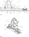
- Fig. 1 shows an attachment bracket according to an embodiment of the invention arranged on a roof comprising a roof deck 100 and roof tiles 101 of which only one is shown in Fig. 1.
- Fig. 2 is an exploded view which shows the different parts of an attachment bracket 1 according to the embodiment of the invention in Fig. 1 .
- the attachment bracket 1 is arranged to attach equipment parts on the roof which is constituted by the roof deck 100 on which roof tiles 101 are arranged, wherein the attachment bracket 1 comprises an engagement portion 2, for attachment on the roof deck 100 along an engagement direction 3, and an attachment portion 4 for interaction with said equipment parts which in the shown embodiment is a snow slide protection comprising three parallel pipes 20.
- the attachment bracket 1 exhibits a height direction 5, which is essentially perpendicular to the engagement direction 3.
- the attachment bracket comprises a main bracket 6 and an auxiliary bracket 7.
- the main bracket 6 and the auxiliary bracket 7 are constituted by bent and punched components of sheet steel. This is an uncomplicated manufacturing method which allows manufacturing of the attachment brackets at a low cost.
- the attachment portion 4 is arranged on the main bracket 6, and the engagement portion 2 is arranged on the auxiliary bracket 7.
- the main bracket 6 which is shown in the embodiment in Fig. 1 and 2 comprises apart from the attachment portion 4 a base portion 12 which is bent at an angle in relation to the attachment portion 4.
- the base portion 12 is especially useful when only the main bracket 6 is used, which is possible for example on a profiled sheet metal roof or a roof with a sealing layer.
- the attachment portion 4 comprises a set of first holes 8 and the engagement portion 2 comprises a plurality of sets of second holes 9, 9', 9".
- the set of first holes 8 is intended for interaction with one of said plurality of sets of second holes 9, 9', 9'', for mutual fixation of the main bracket 6 in relation to the auxiliary bracket 7.
- the lowest set of second holes 9'' is used so that the main bracket 6 is positioned in its lowest position closest to the roof.
- profile height h of the roof tile 101 is shown. The profile height affects how close to the roof deck 100 it is possible to position equipment parts.
- the attachment portion 4 comprises a set of attachment holes 13, of which only a few are marked in Fig. 2 .
- the attachment holes 13 are arranged for attachment of said equipment parts in one of a plurality of different angles around a geometrical axis which extends transverse to the attachment portion.
- the equipment parts may for example be constituted by a gangway.
- Equipment parts and applications of the attachment bracket 1 will be described in more detail in connection with the description of Fig. 5 below.
- the engagement portion 2 comprises a plurality of, in the height direction arranged, sets of engagement recesses 11, 11', 11'', which in the shown embodiment is constituted by holes.
- the attachment portion 4 comprises a set of engagement elements 10 for interaction with one of the sets of engagement recesses 11, 11', 11''.
- the engagement elements 10 are constituted by sheet metal projections which are bent outwards and which are continuous with and essentially in the same plane as the base portion 12.
- the auxiliary bracket 7 comprises a support portion 15 bent at an angle in relation to the engagement portion 2.
- the support portion 15 provides a support surface against a roof tile 101 on the roof, wherein the edge between the engagement portion 2 and the support portion 15 defines the engagement direction 3.
- the auxiliary bracket 7 comprises a projection 16 which extends from the support portion 15 along the engagement direction 3 and which is arranged for attachment on an attachment pipe 19, which extends transverse to the engagement direction 3 higher up on the roof deck 100.
- the attachment portion 4 exhibits recesses 14 for protection rack pipes and/or recesses 21 for an elongated snow slide protection profile to be supported by the attachment bracket 1.
- Fig. 1 three parallel pipes 20 are arranged in the recesses 14.
- FIG. 2 it is shown how the attachment bracket 1 can be assembled and attached on a roof deck 100 ( Fig. 1 ).
- the attachment pipe 19 is attached on the roof deck 100 by means of attachment clamps 22 which are fastened with the screws 23.
- a similar attachment clamp 24 is used to attach the projection 16 to the attachment pipe 19.
- the attachment clamp 24 is attached to the projection 16 with the screws 25 and the nuts 26 so that the attachment clamp 24 and the projection 16 encloses the attachment pipe 19.
- the auxiliary bracket 7 is attached to the roof deck 100.
- the auxiliary bracket 7 is positioned on top of a roof tile 101 as is shown in Fig. 1 .
- the main bracket 6 is positioned with the engagement elements 10 in engagement with one of the engagement recesses 11, 11', 11'', so that the main bracket 6 is positioned at a suitable height in relation to the top of the profiles of the roof tiles 101.
- the main bracket 6 is then attached to the auxiliary bracket 7 by means of the assembly screws 27 and the assembly nuts 28 through the set of first holes 8 and one of said sets of second holes 9, 9', 9''. It is of course possible to attach the main bracket 6 to the auxiliary bracket 7 before the auxiliary bracket 7 is attached to the attachment pipe 19.
- Fig. 2 only one roof tile 101 is shown.
- the next following roof tile further up on the roof is laid so that it covers the projection 16 and the top part of the shown roof tile 101. Thanks to the fact that the projection 16 being strip formed the projection 16 does not affect the placement of the next above lying roof tile which thus may be positioned in the way prescribed by the manufacturer of the roof tiles.
- Fig. 3 is a side view of the assembled attachment bracket 1 in Fig. 1 and Fig. 2 when it is assembled on a roof deck 100.
- the roof deck 100 comprises roof trusses 102 on which there is arranged a support layer 103.
- the screws 23 which attaches the attachment clamps 22 in the roof are screwed into the roof trusses 102.
- the main bracket 6 is arranged in its lowest position in relation to the auxiliary bracket 7.
- the assembly screws 27 are arranged in the lowest set of second holes 9''.
- the engagement elements 10 are in engagement with the lowest set of engagement recesses 11''.
- no roof tile 101 ( Fig. 1 ) is shown in Fig. 3 .
- Fig. 4 shows how a part of the attachment bracket 1 can be used on a folding sheet metal roof. More specifically the main bracket 6 is used together with a side auxiliary bracket 17 and attachment means 18 which for example may be screws.
- the side auxiliary bracket 17 extends along the main bracket 6.
- Said attachment means 18 is arranged to tighten the side auxiliary bracket 17 in the direction towards the main bracket 6 so that a fold on a sheet metal roof can be pinched between the side auxiliary bracket 17 and the main bracket 6.
- the main bracket 6 has engagement elements 10 which extends from the base portion 12.
- the side auxiliary bracket 17 comprises a set of second engagement elements 29, which in Fig. 4 are displaced in relation to the engagement elements 10 on the main bracket 6.
- the engagement elements 10 and the second engagement elements 29 together contribute to that the main bracket 6 can be attached securely on a folding sheet metal roof.
- Fig 5 is an overview image which shows different fields of application for the entire or parts of the attachment bracket 1 according to the invention.
- the attachment bracket may be used on different sorts of roofs.
- different sorts of equipment which may be attached to the roof using the attachment bracket 1 are shown.
- the first three columns only a part of the attachment bracket 1 is used, namely the main bracket 6.
- the roof is a folding sheet metal roof, wherein the attachment is made using the main bracket 6 as has been described in relation to Fig. 4 .
- the roof is a roof with a sealing layer, wherein an attachment plate 30 is used, which is arranged below the sealing layer.
- a sealing layer (not shown in Fig.
- a ridge rack 31 is shown arranged in the attachment bracket 1.
- a snow slide protection in the form of three pipes 32 is shown.
- a snow slide protection in the form of a profile deck 33 is shown.
- a gangway 34 is shown.
Landscapes
- Engineering & Computer Science (AREA)
- Architecture (AREA)
- Civil Engineering (AREA)
- Structural Engineering (AREA)
- Roof Covering Using Slabs Or Stiff Sheets (AREA)
Applications Claiming Priority (1)
| Application Number | Priority Date | Filing Date | Title |
|---|---|---|---|
| SE1551566 | 2015-12-01 |
Publications (1)
| Publication Number | Publication Date |
|---|---|
| EP3176343A1 true EP3176343A1 (de) | 2017-06-07 |
Family
ID=20300779
Family Applications (1)
| Application Number | Title | Priority Date | Filing Date |
|---|---|---|---|
| EP16200641.5A Withdrawn EP3176343A1 (de) | 2015-12-01 | 2016-11-25 | Befestigungsklammer für dachausrüstung |
Country Status (1)
| Country | Link |
|---|---|
| EP (1) | EP3176343A1 (de) |
Cited By (7)
| Publication number | Priority date | Publication date | Assignee | Title |
|---|---|---|---|---|
| EP3760806A1 (de) | 2019-07-02 | 2021-01-06 | Piristeel Oy | Befestigungsvorrichtung, anordnung und verfahren zur montage von zubehörvorrichtungen |
| EP3904620A1 (de) | 2020-04-28 | 2021-11-03 | Eternit Österreich GmbH | Befestigungsanordnung |
| SE2051139A1 (en) * | 2020-09-30 | 2022-03-31 | Cwl Patent Ab | Securing arrangement |
| EP3978702A1 (de) * | 2020-09-30 | 2022-04-06 | CWL Patent AB | Befestigungsanordnung zur befestigung von dachausrüstungen an einem dach |
| RU212198U1 (ru) * | 2021-12-22 | 2022-07-11 | Общество с ограниченной ответственностью "Управляющая компания "Промтехкомплект" | Снегоудерживающее устройство |
| EP4079988A1 (de) * | 2021-04-19 | 2022-10-26 | CWL Patent AB | Laufsteganordnung für ein dach |
| SE2350592A1 (en) * | 2023-05-16 | 2024-11-17 | Cwl Patent Ab | An attachment arrangement for the attachment of one or more roof equipment devices |
Citations (8)
| Publication number | Priority date | Publication date | Assignee | Title |
|---|---|---|---|---|
| US1230363A (en) * | 1916-02-15 | 1917-06-19 | William J Baird | Snow-guard. |
| FR2515236A3 (fr) * | 1981-10-23 | 1983-04-29 | Willa Siegfried | Dispositif de fixation d'une barriere de retenue de la neige |
| DE9003060U1 (de) * | 1990-03-13 | 1991-07-18 | Friedrich Wiegand GmbH, 5820 Gevelsberg | Sicherheitssteigrost und Schneefänger |
| DE9103193U1 (de) * | 1991-03-15 | 1992-07-16 | Lonevag Beslagfabrikk A/S, Lonevag | Beschlag für Gebrauch auf bandgedecktem Dach |
| SE524705C2 (sv) | 2002-09-12 | 2004-09-21 | Cw Lundberg Ind Ab | Anordning för fastsättning av takutrustning på ett falsat plåttak |
| DE202005000694U1 (de) * | 2005-01-14 | 2005-04-07 | Flender Fa Wilhelm | Klemmvorrichtung |
| DE202004007940U1 (de) * | 2004-05-14 | 2005-09-29 | Claussen, Sven | Halterung für einen Blumenkasten |
| EP1852562A2 (de) * | 2006-05-05 | 2007-11-07 | CW Lundberg Industri AB | Halterung für eine Dacheinrichtung, Dachschutzsystem und Verfahren zur Montage eines Dachschutzsystems |
-
2016
- 2016-11-25 EP EP16200641.5A patent/EP3176343A1/de not_active Withdrawn
Patent Citations (8)
| Publication number | Priority date | Publication date | Assignee | Title |
|---|---|---|---|---|
| US1230363A (en) * | 1916-02-15 | 1917-06-19 | William J Baird | Snow-guard. |
| FR2515236A3 (fr) * | 1981-10-23 | 1983-04-29 | Willa Siegfried | Dispositif de fixation d'une barriere de retenue de la neige |
| DE9003060U1 (de) * | 1990-03-13 | 1991-07-18 | Friedrich Wiegand GmbH, 5820 Gevelsberg | Sicherheitssteigrost und Schneefänger |
| DE9103193U1 (de) * | 1991-03-15 | 1992-07-16 | Lonevag Beslagfabrikk A/S, Lonevag | Beschlag für Gebrauch auf bandgedecktem Dach |
| SE524705C2 (sv) | 2002-09-12 | 2004-09-21 | Cw Lundberg Ind Ab | Anordning för fastsättning av takutrustning på ett falsat plåttak |
| DE202004007940U1 (de) * | 2004-05-14 | 2005-09-29 | Claussen, Sven | Halterung für einen Blumenkasten |
| DE202005000694U1 (de) * | 2005-01-14 | 2005-04-07 | Flender Fa Wilhelm | Klemmvorrichtung |
| EP1852562A2 (de) * | 2006-05-05 | 2007-11-07 | CW Lundberg Industri AB | Halterung für eine Dacheinrichtung, Dachschutzsystem und Verfahren zur Montage eines Dachschutzsystems |
Cited By (11)
| Publication number | Priority date | Publication date | Assignee | Title |
|---|---|---|---|---|
| EP3760806A1 (de) | 2019-07-02 | 2021-01-06 | Piristeel Oy | Befestigungsvorrichtung, anordnung und verfahren zur montage von zubehörvorrichtungen |
| EP3904620A1 (de) | 2020-04-28 | 2021-11-03 | Eternit Österreich GmbH | Befestigungsanordnung |
| AT523769A1 (de) * | 2020-04-28 | 2021-11-15 | Eternit Oesterreich Gmbh | Befestigungsanordnung |
| AT523769B1 (de) * | 2020-04-28 | 2022-02-15 | Eternit Oesterreich Gmbh | Befestigungsanordnung |
| SE2051139A1 (en) * | 2020-09-30 | 2022-03-31 | Cwl Patent Ab | Securing arrangement |
| EP3978702A1 (de) * | 2020-09-30 | 2022-04-06 | CWL Patent AB | Befestigungsanordnung zur befestigung von dachausrüstungen an einem dach |
| EP4079988A1 (de) * | 2021-04-19 | 2022-10-26 | CWL Patent AB | Laufsteganordnung für ein dach |
| RU212198U1 (ru) * | 2021-12-22 | 2022-07-11 | Общество с ограниченной ответственностью "Управляющая компания "Промтехкомплект" | Снегоудерживающее устройство |
| SE2350592A1 (en) * | 2023-05-16 | 2024-11-17 | Cwl Patent Ab | An attachment arrangement for the attachment of one or more roof equipment devices |
| EP4464856A1 (de) * | 2023-05-16 | 2024-11-20 | CWL Patent AB | Befestigungsanordnung zur befestigung einer oder mehrerer dachausrüstungsvorrichtungen |
| SE546997C2 (en) * | 2023-05-16 | 2025-03-25 | Cwl Patent Ab | An attachment arrangement for the attachment of one or more roof equipment devices |
Similar Documents
| Publication | Publication Date | Title |
|---|---|---|
| EP3176343A1 (de) | Befestigungsklammer für dachausrüstung | |
| US8776456B1 (en) | Solar panel tile roof mounting device | |
| US12244260B2 (en) | Roof mounting system | |
| US8806815B1 (en) | Adjustable solar panel tile roof mounting device | |
| EP2666925B1 (de) | Verbundstruktur eines isolierten Paneels und Belagblech mit entsprechenden Befestigungsmitteln zur Anwendung in Baukonstruktionen | |
| US20170260753A1 (en) | Peripheral stabilizing system for elevated flooring surface | |
| US10947732B2 (en) | Adjustable skylight guard | |
| US20100308181A1 (en) | Pipe support base | |
| EP4184018A1 (de) | Dachbefestigungskonsole | |
| EP3663479B1 (de) | Befestigungselement für dachsicherheitsprodukte | |
| JP6751303B2 (ja) | 固定用金具 | |
| EP1717384B1 (de) | Halterung für Dachaufsatzkomponenten | |
| US20140215960A1 (en) | Grating Clamp and Method for Fixing a Grating to a Support | |
| EP3252320A1 (de) | Kopplungssystem auf wulstflachprofil | |
| EP2770133B1 (de) | Aufdach-Befestigungsvorrichtung | |
| WO2005071180A1 (en) | Holding assembly for holding a building sheet | |
| GB2499324A (en) | Fixing bracket system for a tiled or slate roof | |
| DE102015100678A1 (de) | Vorrichtung zum Befestigen von Verblendsteinen, insbesondere für den Fassadenbau, Trägerprofil und Verblendstein | |
| US20180127994A1 (en) | Working deck netting system and related methodology | |
| EP3377712B1 (de) | Längliches element für bedachungsplattenmontage, bedachungsplattensystem und dach damit | |
| JP6797419B2 (ja) | 屋根上設置物を取付けるための取付部材の施工方法、及び、取付部材の固定構造 | |
| US20170342715A1 (en) | Roofing batten | |
| JP2007100380A (ja) | 屋根上架台装置及び架台瓦 | |
| JP5661845B2 (ja) | 可搬式屋根材歩行体験装置 | |
| AU2013206716A1 (en) | Handrail Support Device |
Legal Events
| Date | Code | Title | Description |
|---|---|---|---|
| AK | Designated contracting states |
Kind code of ref document: A1 Designated state(s): AL AT BE BG CH CY CZ DE DK EE ES FI FR GB GR HR HU IE IS IT LI LT LU LV MC MK MT NL NO PL PT RO RS SE SI SK SM TR |
|
| AX | Request for extension of the european patent |
Extension state: BA ME |
|
| PUAI | Public reference made under article 153(3) epc to a published international application that has entered the european phase |
Free format text: ORIGINAL CODE: 0009012 |
|
| STAA | Information on the status of an ep patent application or granted ep patent |
Free format text: STATUS: THE APPLICATION IS DEEMED TO BE WITHDRAWN |
|
| 18D | Application deemed to be withdrawn |
Effective date: 20171208 |