EP2667023A2 - Commande d'un système d'énergie éolienne - Google Patents
Commande d'un système d'énergie éolienne Download PDFInfo
- Publication number
- EP2667023A2 EP2667023A2 EP13163659.9A EP13163659A EP2667023A2 EP 2667023 A2 EP2667023 A2 EP 2667023A2 EP 13163659 A EP13163659 A EP 13163659A EP 2667023 A2 EP2667023 A2 EP 2667023A2
- Authority
- EP
- European Patent Office
- Prior art keywords
- wind
- wind turbine
- control device
- energy system
- performance
- Prior art date
- Legal status (The legal status is an assumption and is not a legal conclusion. Google has not performed a legal analysis and makes no representation as to the accuracy of the status listed.)
- Granted
Links
Images


Classifications
-
- F—MECHANICAL ENGINEERING; LIGHTING; HEATING; WEAPONS; BLASTING
- F03—MACHINES OR ENGINES FOR LIQUIDS; WIND, SPRING, OR WEIGHT MOTORS; PRODUCING MECHANICAL POWER OR A REACTIVE PROPULSIVE THRUST, NOT OTHERWISE PROVIDED FOR
- F03D—WIND MOTORS
- F03D7/00—Controlling wind motors
- F03D7/02—Controlling wind motors the wind motors having rotation axis substantially parallel to the air flow entering the rotor
- F03D7/04—Automatic control; Regulation
- F03D7/042—Automatic control; Regulation by means of an electrical or electronic controller
- F03D7/048—Automatic control; Regulation by means of an electrical or electronic controller controlling wind farms
-
- F—MECHANICAL ENGINEERING; LIGHTING; HEATING; WEAPONS; BLASTING
- F03—MACHINES OR ENGINES FOR LIQUIDS; WIND, SPRING, OR WEIGHT MOTORS; PRODUCING MECHANICAL POWER OR A REACTIVE PROPULSIVE THRUST, NOT OTHERWISE PROVIDED FOR
- F03D—WIND MOTORS
- F03D7/00—Controlling wind motors
- F03D7/02—Controlling wind motors the wind motors having rotation axis substantially parallel to the air flow entering the rotor
- F03D7/0264—Controlling wind motors the wind motors having rotation axis substantially parallel to the air flow entering the rotor for stopping; controlling in emergency situations
-
- F—MECHANICAL ENGINEERING; LIGHTING; HEATING; WEAPONS; BLASTING
- F05—INDEXING SCHEMES RELATING TO ENGINES OR PUMPS IN VARIOUS SUBCLASSES OF CLASSES F01-F04
- F05B—INDEXING SCHEME RELATING TO WIND, SPRING, WEIGHT, INERTIA OR LIKE MOTORS, TO MACHINES OR ENGINES FOR LIQUIDS COVERED BY SUBCLASSES F03B, F03D AND F03G
- F05B2270/00—Control
- F05B2270/10—Purpose of the control system
- F05B2270/103—Purpose of the control system to affect the output of the engine
- F05B2270/1033—Power (if explicitly mentioned)
-
- F—MECHANICAL ENGINEERING; LIGHTING; HEATING; WEAPONS; BLASTING
- F05—INDEXING SCHEMES RELATING TO ENGINES OR PUMPS IN VARIOUS SUBCLASSES OF CLASSES F01-F04
- F05B—INDEXING SCHEME RELATING TO WIND, SPRING, WEIGHT, INERTIA OR LIKE MOTORS, TO MACHINES OR ENGINES FOR LIQUIDS COVERED BY SUBCLASSES F03B, F03D AND F03G
- F05B2270/00—Control
- F05B2270/10—Purpose of the control system
- F05B2270/111—Purpose of the control system to control two or more engines simultaneously
-
- F—MECHANICAL ENGINEERING; LIGHTING; HEATING; WEAPONS; BLASTING
- F05—INDEXING SCHEMES RELATING TO ENGINES OR PUMPS IN VARIOUS SUBCLASSES OF CLASSES F01-F04
- F05B—INDEXING SCHEME RELATING TO WIND, SPRING, WEIGHT, INERTIA OR LIKE MOTORS, TO MACHINES OR ENGINES FOR LIQUIDS COVERED BY SUBCLASSES F03B, F03D AND F03G
- F05B2270/00—Control
- F05B2270/30—Control parameters, e.g. input parameters
- F05B2270/301—Pressure
-
- F—MECHANICAL ENGINEERING; LIGHTING; HEATING; WEAPONS; BLASTING
- F05—INDEXING SCHEMES RELATING TO ENGINES OR PUMPS IN VARIOUS SUBCLASSES OF CLASSES F01-F04
- F05B—INDEXING SCHEME RELATING TO WIND, SPRING, WEIGHT, INERTIA OR LIKE MOTORS, TO MACHINES OR ENGINES FOR LIQUIDS COVERED BY SUBCLASSES F03B, F03D AND F03G
- F05B2270/00—Control
- F05B2270/30—Control parameters, e.g. input parameters
- F05B2270/303—Temperature
-
- F—MECHANICAL ENGINEERING; LIGHTING; HEATING; WEAPONS; BLASTING
- F05—INDEXING SCHEMES RELATING TO ENGINES OR PUMPS IN VARIOUS SUBCLASSES OF CLASSES F01-F04
- F05B—INDEXING SCHEME RELATING TO WIND, SPRING, WEIGHT, INERTIA OR LIKE MOTORS, TO MACHINES OR ENGINES FOR LIQUIDS COVERED BY SUBCLASSES F03B, F03D AND F03G
- F05B2270/00—Control
- F05B2270/30—Control parameters, e.g. input parameters
- F05B2270/335—Output power or torque
-
- F—MECHANICAL ENGINEERING; LIGHTING; HEATING; WEAPONS; BLASTING
- F05—INDEXING SCHEMES RELATING TO ENGINES OR PUMPS IN VARIOUS SUBCLASSES OF CLASSES F01-F04
- F05B—INDEXING SCHEME RELATING TO WIND, SPRING, WEIGHT, INERTIA OR LIKE MOTORS, TO MACHINES OR ENGINES FOR LIQUIDS COVERED BY SUBCLASSES F03B, F03D AND F03G
- F05B2270/00—Control
- F05B2270/30—Control parameters, e.g. input parameters
- F05B2270/337—Electrical grid status parameters, e.g. voltage, frequency or power demand
-
- Y—GENERAL TAGGING OF NEW TECHNOLOGICAL DEVELOPMENTS; GENERAL TAGGING OF CROSS-SECTIONAL TECHNOLOGIES SPANNING OVER SEVERAL SECTIONS OF THE IPC; TECHNICAL SUBJECTS COVERED BY FORMER USPC CROSS-REFERENCE ART COLLECTIONS [XRACs] AND DIGESTS
- Y02—TECHNOLOGIES OR APPLICATIONS FOR MITIGATION OR ADAPTATION AGAINST CLIMATE CHANGE
- Y02E—REDUCTION OF GREENHOUSE GAS [GHG] EMISSIONS, RELATED TO ENERGY GENERATION, TRANSMISSION OR DISTRIBUTION
- Y02E10/00—Energy generation through renewable energy sources
- Y02E10/70—Wind energy
- Y02E10/72—Wind turbines with rotation axis in wind direction
Definitions
- the invention relates to a wind energy system, in particular an offshore wind energy system, comprising a first wind turbine and at least one further wind turbine, the wind turbines each having a power detection means for detecting the actual value of the output power, and at least one connected via a communication network with the Windkaftanlagen controller , Moreover, the invention relates to a method for controlling a wind energy system and a computer program for carrying out the method.
- a wind turbine converts the kinetic energy of the wind into electrical energy by means of a rotor and a generator.
- a wind energy system or a wind farm can be formed from several wind turbines.
- the wind turbines can be set up especially in areas with high wind probability and intensity.
- sites on the open sea, also called offshore areas are especially suitable.
- a disadvantage of the prior art is that only the actual value of the current power generated by a wind turbine is considered at a required power reduction. Otherwise, any selection of wind turbines to be switched off takes place.
- By taking into account only the actual values of the delivered power when selecting the wind turbines to be switched off continue to operate in the prior art wind turbines whose operability, in particular its performance and reliability, is lower than the operability of deactivated wind turbines. This can further reduce the operability of the activated wind turbines and even lead to a failure of a wind turbine. The reliability of the operation of the wind energy system is reduced.
- the invention is therefore based on the object of providing a wind energy system and a method for controlling a wind energy system which, with a required power reduction, ensures that the wind turbines with a better operating capability are continued to operate.
- the object is achieved in a wind energy system, in particular an offshore wind energy system, according to claim 1.
- the wind energy system comprises a first wind turbine and at least one further wind turbine.
- the wind turbines each have a power detection device for detecting the actual value of the output power.
- the wind energy system comprises at least one control device connected via a communication network to the wind power plants.
- the first wind turbine has at least one operating state detection device for detecting at least one operating parameter of the first wind turbine.
- the further wind turbine has at least one operating state detection device for detecting at least one operating parameter of the further wind turbine.
- the control device is to set up to determine a performance identifier for the first wind turbine at least as a function of the operating parameter of the first wind turbine.
- the control device is set up to determine a performance identifier for the further wind turbine at least as a function of the operating parameter of the further wind turbine.
- the control device is set up to deactivate at least one wind power plant as a function of the performance identifications when a power reduction is required.
- the selection of the wind turbine / s to be deactivated is not carried out arbitrarily, but as a function of the respective operating state of the wind power plants.
- the wind power plant can be deactivated, which is (currently) in a worse compared to the at least one other wind turbine operating condition. As a result, a more reliable operation of the wind energy system can be ensured.
- the wind energy system comprises at least two wind turbines.
- a plurality of wind turbines may be integrated in a wind energy system.
- a wind turbine is adapted to convert the kinetic energy of the wind by means of a generator device into electrical power.
- the electrical power can be fed via power cables and substations in a network.
- a control device For controlling the wind power plants, a control device is provided.
- a central control device for example in the form of a data processing system for at least a wind energy system may be provided.
- a communication network is installed for communication with the wind turbines.
- the communication network may include wired and / or wireless communication channels. Data can be exchanged between the control device and the wind power plants via the communication network. For example, sensor data from the wind turbines to the control device and / or the control device control signals can be transmitted to the wind turbines. It is understood that further data can be exchanged over the communication network.
- Each wind turbine may include a power detector.
- a power detection device is set up to detect the currently generated power, ie the actual value of the output of the wind power plant. If the requirement for power reduction occurs, for example, on the basis of an instruction of a network operator and a maximum nominal value is present, in particular the number of wind energy devices to be deactivated can be determined as a function of the actual values. This can prevent an unnecessary power reduction from occurring.
- the selection of which wind turbines are actually turned on, is determined according to the invention on the basis of the respective performance identifier of the wind turbines.
- the performance identifier may in particular be a "key performance indicator".
- the performance identifier may represent a (total) performance and / or operability of the respective wind turbine.
- the Performance identifier can be considered at least the current operating condition of the wind turbine.
- the wind power plant has at least one operating state detection device.
- at least one sensor may be provided.
- at least one operating parameter preferably a plurality of operating parameters, can be detected by the at least one operating state detection device.
- Exemplary and non-exhaustive operating parameters are the temperature of a component of the wind turbine, the temperature of the wind turbine tower, the condition of the foundation of the wind turbine tower, the purity of the lubricating oil used, a line pressure, the condition of the rotor blades, the condition of a protection system such as a fire protection system, etc.
- the performance identifier is derived or determined by the control device from at least one particularly current operating parameter.
- the performance identifier can be a numerical value.
- a high performance of a wind turbine can be represented by a high numerical value and a low performance of a wind turbine by a low numerical value.
- a reverse division is also conceivable. A simple assessment of the respective condition of the wind turbines is given.
- Non-exhaustive examples of factors that may result in a lower performance identifier are operating parameters that are current from a normal range differ. For example, a too high (or too low) temperature value of a component, too high (or too low) line pressure, excessive contamination of the lubricating oil, etc. Also, an activated protection device can reduce the performance identifier. Conversely, particularly good current operating parameters can increase the performance of a wind turbine.
- the control device can evaluate the current performance identifications of the at least two wind power plants and, depending on the evaluation, transmit a control signal, in particular a deactivation signal, to the wind power plant / s to be deactivated.
- the wind energy system can be operated with increased reliability.
- the control device can be set up to compare the performance indicators of the wind power plants with one another.
- a comparison operation can in a simple and in particular timely manner, for example by a Software and / or hardware module are performed in the control device. It is particularly easy and fast to compare numerical values.
- the control device can be set up to deactivate at least one wind power plant as a function of the comparison result in the event of a required power reduction. As already described, the control device can transmit a control signal, in particular a deactivation signal, to the respective wind turbine / s.
- an even more meaningful performance identifier for a wind turbine can be generated if additional historical operating data of the wind turbine are used in the determination of the performance identifier.
- historical operating parameters can provide information about the reliability of the wind turbine. If in the past a wind turbine has exhibited increased operating values that have deviated from a normal operating state, or if a wind turbine has failed one or more times in the past, this may indicate lower performance and reliability.
- an operating state detection device can be set up to detect the operating parameter continuously or at predefinable time intervals. For example, an operating parameter can be recorded regularly.
- a database may be provided for storing the acquired operating parameter values.
- the Database be connected to the controller.
- all parameter values of preferred all operating parameters may be stored in the database.
- the control device can be set up to determine the performance identifier of the wind power plant as a function of the stored operating parameter values.
- the historical operating parameters can be analyzed and evaluated by the control device.
- a statistical evaluation of the stored operating parameters can take place. For example, the frequency of certain error messages, the frequency of occurrence of deviations and / or the frequency of failures of each wind turbine can be determined. Furthermore, the duration of a failure or the duration of exceeding of normal operating parameter ranges may be determined. From this, parameters such as average failure duration, average duration between two failures, average duration of deviation of an operation parameter from a normal range, and the like can be determined. When determining the respective performance identifier, these parameters can be taken into account. This allows more reliable wind turbines to continue operating at a required power reduction, while unreliable wind turbines can be deactivated.
- environmental parameters may be taken into account when determining the performance identifier of a wind turbine.
- environmental parameters such as environmental meteorological parameters
- a wind turbine may have a higher performance than another wind turbine in the same wind conditions.
- at least one detection device may be provided for detecting at least one environmental parameter, in particular a current meteorological environmental parameter.
- the control device can be set up to determine the performance identifier of a wind turbine as a function of the environmental parameter.
- the at least one meteorological measuring device may in particular be a wind measuring mast for detecting the current wind speed and / or wind direction and / or a measuring buoy for determining the current sea state.
- the selection of a wind turbine to be shut down from a plurality of wind turbines can be further improved.
- a wind power plant may have a plurality of sub-assemblies or components.
- the wind turbine can be divided into a plurality of sub-devices, which can form a technical unit.
- a wind turbine can have at least one sub-device according to an embodiment.
- the control device can be set up to determine at least one sub-power identifier of the subassembly of the wind power plant.
- at least one operating detection device may be provided for detecting an operating parameter of the sub-device.
- the determination of a sub-performance identifier can be determined as previously described in connection with the determination of a performance identifier. By the Determining a sub-performance identifier, the performance of a sub-device can be made available.
- Exemplary and non-exhaustive subassemblies of a wind turbine are a generator device, an air conditioning device, a rotor device, a tower foundation, a measuring device, etc. It is understood that a sub-device can in turn be divided into at least one further sub-device.
- the control device may be configured to determine the performance identifier of the wind turbine from a plurality of sub-performance codes of a wind turbine.
- a wind turbine for determining the power identifier can be considered.
- the performance identifier may be estimated from the sub-performance identifiers.
- the control device may preferably have a module for calculating the performance identifier. For example, by integration and / or summation of the sub-performance identifier, the performance identifier can be determined. It is understood that normalization can be performed to easily compare the performance characteristics of various wind turbines.
- control device may be configured to assign at least one sub-performance identifier to at least one weighting factor.
- each sub-power identifier can be assigned a weighting factor.
- the weighting factor is in particular a measure of how strong the influence of a sub-device on the overall operability of the wind turbine. As a result, the influence of a sub-device on the operability of the wind turbine can be considered.
- a low-impact sub-device may be coupled with a low weighting factor and a large-impact sub-device with a correspondingly larger weighting factor.
- the determination of the respective weighting factor can be done manually and / or automatically. For example, it can be automatically derived from historical data which sub-devices are particularly relevant to the operability of the wind turbine and which are less relevant.
- the control device may be configured to generate a model of at least one wind turbine.
- the entire wind energy system can be imaged as a virtual model in the control device.
- the performance identifier of a wind turbine can be determined.
- the control device can be set up to simulate a performance identification process of the wind power plant by means of the model.
- a suitable software program such as Matlab can be used.
- the influence of at least one environmental parameter, such as the sea state or the wind speed can additionally be taken into account.
- a performance identification process can be predicted by the simulation by the control device.
- the control device can be set up to deactivate at least one wind power plant as a function of the simulation result in the event of a required power reduction.
- the power reduction may be predetermined for a certain period of time.
- the control device can simulate the power recognition process, in particular as a function of predicted meteorological parameters, for this period of time.
- the wind turbine with the predicted lowest performance identifier can be deactivated.
- the simulations may already have been performed during normal operation of the wind energy system and stored in a database. If necessary, then a comparison of the stored data can be performed. The selection of the wind turbine to be deactivated can take place in a timely manner.
- a further aspect of the invention is a method for controlling a wind energy system, in particular an offshore wind energy system, comprising a first wind turbine and at least one further wind turbine.
- the method includes detecting the actual values of the output of the wind turbines. At least one first operating parameter of a first wind turbine is detected. At least one further operating parameter of at least one further wind turbine is detected.
- a performance identifier for the first wind turbine is determined at least as a function of the operating parameter of the first wind turbine. At least one further performance identifier for the further wind turbine is determined as a function of the operating parameter of the further wind turbine. For a required power reduction, at least one wind turbine is deactivated depending on the performance identifiers.
- the method can be used in particular in a previously described wind energy system.
- the method allows to easily continue the wind turbines, which have a high reliability and operability, while the wind turbines can be deactivated, whose reliability and operability are lower.
- Yet another aspect of the invention is a computer program having instructions executable on a processor such that a wind energy system is controlled according to the method described above.
- FIG. 1 shows a schematic view of a first embodiment of a wind energy system 2 according to the present invention.
- the wind energy system 2 comprises a control device 4, which is connected via a communication network 8 to a first wind turbine 6.1 and a further wind turbine 6.2. It is understood that more than two wind turbines 6.1, 6.2 can be provided.
- the communication network 8 may include wired and / or wireless communication channels.
- a wind turbine 6.1, 6.2 is designed to convert the kinetic energy of the wind into electrical energy. About (not shown) power cables and, where appropriate, substations, the electricity generated in a (public) network can be fed.
- a wind power plant 6.1, 6.2 may have a power detection device 7 for detecting the currently emitted power.
- a Power meter 7 may be provided. The actual values of the delivered power can be transmitted to the control device 4.
- the wind turbines each have an operating state detection device 16a in the present embodiment.
- the operating state detection device 16a is set up to detect at least one operating parameter or state parameter of the wind power plant 6.1, 6.2.
- the control device 4 may in particular be a data processing system, such as a computer or the like.
- the control device 4 may comprise a database or be connected to a database 5.
- a display device 12 such as a display 12, is also provided for displaying information.
- interface means 14 may be provided, for example, in the form of a keyboard, a mouse, a touchscreen, etc.
- the control device 4 can be arranged in particular in a control room.
- control device 4 can receive a signal via a further data input 10.
- the signal may in particular be a power generation information signal.
- This signal can be used to specify how much energy should be generated for a certain period of time. For example, it may be provided that at least one of the at least two wind turbines has to be deactivated in order to comply with the given target energy.
- control device 4 If the control device 4 receives a corresponding signal, it can preferably be determined automatically by the control device 4 which wind turbine 6.1, 6.2 is deactivated. It has been recognized that preferably the wind turbine 6.1, 6.2 should be deactivated, which has a lower efficiency or operability.
- the control device 4 for the at least two wind turbines 6.1, 6.2 determine a performance identifier.
- the determination of the respective performance identifier can be done in different ways.
- At least one (current) operating parameter of the respective wind power plant 6.1, 6.2 is recorded and taken into account.
- a current operating parameter of the first wind turbine 6.1 may have a value that is better than a normal range than the same operating parameter of the further wind turbine 6.2.
- the technical specification such as the technical properties, functions and / or structures of the respective wind turbine can be read.
- the technical specification may be provided by the manufacturer.
- a wind power plant 6.1, 6.2 compared to the other wind turbine 6.1, 6.2 have a new, improved component.
- the technical specification can for example be analyzed by the control device 4 and corresponding (current) performance identifiers can be created.
- a performance identifier may be a numerical value.
- the numerical values can be compared with each other and, for example, the lowest value can be determined.
- the control device 4 can be set up to deactivate the wind power plant 6.1, 6.2 corresponding to the lowest value via the communication network 8.
- FIG. 2 shows a further schematic view of another embodiment of a wind energy system 2.1 according to the present invention.
- the wind energy system 2.1 is an offshore wind energy system 2.1.
- the offshore wind energy system 2.1 comprises a substation 22.
- the offshore substation 22 or offshore switchgear 22 may in particular comprise a substation. From the switchgear 22, the electrical energy generated can be transmitted via suitable submarine cable 24 directly or via a high-voltage DC transmission platform to a gnbo transformer substation 32 and fed from there into the grid.
- the substation 22 may comprise further subassemblies, such as at least one generator, in particular a diesel generator. A diesel generator makes it possible to maintain operation even if the feedback energy of a high-voltage DC transmission platform is lost.
- the power cables 24 are present as submarine cable 24 formed.
- An energy cable 24 is in particular configured to transmit the electrical energy generated by a wind power plant 6.1, 6.2 to the next wind power plant 6.1, 6.2 or to the substation 22.
- a plurality of wind turbines 6.1, 6.2 are connected in series in a plurality of strands 36 or strings 36.
- eight strands with six wind turbines each may be provided in a wind energy system.
- One end of a strand 36 is electrically connected to the substation 22 via a power cable 24.
- the other end may be electrically connectable via an additional power cable to the end of another strand, for example via a switch device.
- one strand can optionally be connected to a plurality of other strands. It is understood that according to other variants of the invention, the wind turbines 6.1, 6.2 can also be arranged in ring structures.
- a wind power plant 6.1, 6.2 may comprise a plurality of sub-facilities 16.1, 16.2, 18.1, 18.2, 20.1, 20.2.
- a manual transmission 16.1, 16.2, an air conditioning device 18.1, 18.2 and a tower foundation 20.1, 20.2 are shown here.
- a wind turbine 6.1, 6.2 may also have a plurality of sensors.
- a sensor can be set up, for example, to detect at least one operating parameter of a sub-device 16.1, 16.2, 18.1, 18.2, 20.1, 20.2.
- the at least one detected operating parameter can be transmitted to the control device 4 via the communication network 8.
- an operating parameter can be actively transmitted from a sensor to the control device 4 or as a function of a request signal from the control device 4.
- detection means 28, 30 for detecting current environmental parameters, in particular meteorological parameters may be provided in the offshore wind energy system 2.1.
- at least one wind measuring mast 28 may be provided with a wind sensor device 28.1 for detecting the wind direction and / or the wind speed. It goes without saying that a wind measuring mast 28 in addition to at least one wind sensor device 28.1 can have a plurality of further sub-devices.
- a measuring buoy 30 is provided in the present exemplary embodiment.
- a sensor device 30.1 for detecting the swell is shown.
- the measuring buoy 30 may have a plurality of sub-devices.
- a plurality of wind measuring masts and / or measuring buoys can be provided.
- the wind energy system 2.1 comprises a control center 34.
- the control center 34 can be remote from the substation 22 and especially on land.
- the central unit 34 comprises the control device 4 and preferably at least one database 5, at least one display device 12 and at least one input device 14.
- the control device 4 is set up to determine the performance identifiers of the at least two wind power plants 6.1, 6.2. In particular, the control device 4 is set up to determine the sub-performance codes of the respective sub-devices 16.1, 16.2, 18.1, 18.2, 20.1, 20.2.
- At least one (current) operating parameter may be taken into account when determining a sub-power identifier, as explained below.
- historical operating parameters can be taken into account.
- a sensor can be set up to record an operating parameter continuously or at predefinable time intervals, for example periodically. All measured values can be transmitted to the control device 4. The measured values can be stored in the database 5. The historical measured values can be evaluated by the control device 4 for determining a sub-performance identifier.
- the number of previous failures, the average time duration between two failures and the failure duration of a sub-device 16.1, 16.2, 18.1, 18.2, 20.1, 20.2 can be taken into account.
- a required maintenance of a sub-device in the near future 16.1, 16.2, 18.1, 18.2, 20.1, 20.2 and / or the wind turbine 6.1, 6.2, which may result from the historical data can be taken into account in the determination of a performance identifier.
- an associated (total) performance identifier can be determined. For example, by summing the individual sub-performance codes, the (overall) performance identifier can be determined.
- While a defective air conditioning 18.1, 18.2 can affect the performance of a wind turbine 6.1, 6.2 only insignificant, even a potential defect of a gearbox 16.1, 16.2 a wind turbine 6.1, 6.2 have significant impact on performance.
- the individual Subticianskenneptept each with a weighting factor be provided. By means of a weighting factor, the influence described above can be represented and taken into account.
- the control device 4 can deactivate at least one wind power plant 6.1, 6.2 as a function of the (total) power codes. For example, the (total) performance identifiers in the control device 4 can be compared and, in a simple case, the wind power plant 6.1, 6.2 corresponding to the smallest (total) performance identifier can be deactivated.
- the current operating parameters can additionally be used during regular operation of the wind energy system in order to detect a failure of a wind power plant 6.1, 6.2 or (only) one sub-device 16.1, 16.2, 18.1, 18.2, 20.1, 20.2 in a timely manner.
- an optical and / or audible alarm signal can be generated by the control device 4.
- suitable measures for eliminating the disturbance can be initiated.
- FIG. 3 shows a schematic view of another embodiment of a wind energy system 2.2 according to the present invention.
- wind turbine 6 is an offshore wind turbine 6, which is connected via a communication network 8 to the control device 4.
- the wind turbine 6 in the present case comprises three sub-devices 16, 18, 20. It is understood that the Wind turbine 6 may have a variety of other sub-facilities.
- a manual transmission 16, an air conditioning device 18 and a tower foundation 20 are shown.
- a subassembly 16, 18, 20 can have at least one sensor 16a, 16b, 16c, 18a, 20a.
- the tower foundation 20 may include a sensor 20a for detecting the condition of the tower foundation 20. For example, cracks may form in the tower foundation 20 as a result of a movement of the seabed and / or due to the swell of the sea. This can be detected by means of a sensor 20a.
- the air conditioning device 18 may include a sensor 18a.
- a temperature sensor 18a for detecting the current temperature in the tower of the wind turbine 6 may be provided.
- the transmission 16 has three sensors 16a, 16b and 16c in the present embodiment.
- a first sensor 16a may be a vibration sensor 16a.
- a second sensor 16b may be a temperature sensor 16b.
- a third sensor 16c can detect the purity of the lubricating oil used.
- a subassembly 16, 18, 20 may have more than the illustrated sensors 16a, 16b, 16c, 18a, 20a. Furthermore, it is understood that a sensor 16a, 16b, 16c, 18a, 20a may comprise a plurality of measuring heads.
- the sensor data can be transmitted to the control device 4 via a communication network 8 be transmitted.
- historical data and / or current environmental parameters such as meteorological environmental parameters, can also be used to determine a sub-performance identifier.
- sub-designations E i can then be determined.
- a predicted performance identifier can also be determined.
- predicted environmental parameters in particular meteorological environmental parameters, can be taken into account in the case of a predicted power-time characteristic in addition to the current operating parameters and / or historical data.
- control device 4 can be set up to generate a virtual model at least from the wind turbine 6.
- other parameters influencing energy production can be taken into account in the model. These include, for example, environmental parameters, such as meteorological parameters, or the sea state.
- environmental parameters such as meteorological parameters, or the sea state.
- FIGS. 4a and 4b show exemplary predicted performance characteristic curves 38.1, 38.2 at the same environmental parameters for two wind turbines 6.1, 6.2.
- the performance identifier 38.1 of the first wind turbine 6.1 is greater or better than the power identifier 38.2 of the second wind turbine 6.2 up to a time t 1 . From the time t 1 (until the time t 2 ), however, it is the other way round.
- a shutdown of at least one wind turbine 6.1, 6.2 may be present as additional information, the required period of time.
- a power setpoint can be specified for a certain period of time.
- the first wind power plant can be deactivated 6.1.
- Reason for this is the lower performance identifier of the first wind turbine 6.1 between the times 0 and t 2 .
- the simulation may be performed by the controller 4 during normal operation and / or at the time of deactivation of a wind turbine.
- the simulation results can be stored in a database 5 and updated regularly.
- the actual performance identifier of a wind turbine 6 can be compared with the predicted performance identifier of a wind turbine 6. Corresponding results can be analyzed and stored in the database 5.
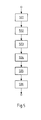
- FIG. 5 a flowchart of an embodiment of a method according to the present invention for controlling at least one wind turbine.
- At least one operating parameter of a wind turbine can be detected.
- a plurality of operating parameters can be detected by a plurality of wind turbines.
- the detection of an operating parameter can take place at specific times or continuously.
- at least one current environmental parameter can be detected and / or historical operating parameters can be provided.
- the control device 4 can determine, in particular from the aforementioned parameters and data, the performance identifier of a wind turbine.
- the service identifier may consist of a plurality be determined by Sub Klaskennept, as previously described.
- all performance identifiers of all wind turbines of the wind energy system are determined. These can be stored in a database.
- the determination is performed at predeterminable time intervals in order to have the most current performance identifiers possible.
- performance identifiers may also be predicted, for example by simulation in a model. These can also be saved.
- step 504 an evaluation of the current and / or predicted performance identifications can be carried out by the control device 4. It is understood that, alternatively, the evaluation may already have been carried out in step 502. In particular, at least the wind turbine can be identified, whose current performance identifier and / or predicted performance identifier is the lowest.
- control device can be in a Step 506, the at least one deactivated wind turbine reactivate.
Landscapes
- Engineering & Computer Science (AREA)
- Life Sciences & Earth Sciences (AREA)
- Sustainable Development (AREA)
- Sustainable Energy (AREA)
- Chemical & Material Sciences (AREA)
- Combustion & Propulsion (AREA)
- Mechanical Engineering (AREA)
- General Engineering & Computer Science (AREA)
- Wind Motors (AREA)
Priority Applications (1)
| Application Number | Priority Date | Filing Date | Title |
|---|---|---|---|
| PL13163659T PL2667023T3 (pl) | 2012-05-21 | 2013-04-15 | Sterowanie systemem energii wiatrowej |
Applications Claiming Priority (1)
| Application Number | Priority Date | Filing Date | Title |
|---|---|---|---|
| DE102012009867A DE102012009867A1 (de) | 2012-05-21 | 2012-05-21 | Steuerung eines Windenergiesystems |
Publications (3)
| Publication Number | Publication Date |
|---|---|
| EP2667023A2 true EP2667023A2 (fr) | 2013-11-27 |
| EP2667023A3 EP2667023A3 (fr) | 2017-03-29 |
| EP2667023B1 EP2667023B1 (fr) | 2018-06-06 |
Family
ID=48095700
Family Applications (1)
| Application Number | Title | Priority Date | Filing Date |
|---|---|---|---|
| EP13163659.9A Active EP2667023B1 (fr) | 2012-05-21 | 2013-04-15 | Commande d'un système d'énergie éolienne |
Country Status (5)
| Country | Link |
|---|---|
| EP (1) | EP2667023B1 (fr) |
| DE (1) | DE102012009867A1 (fr) |
| DK (1) | DK2667023T3 (fr) |
| ES (1) | ES2685815T3 (fr) |
| PL (1) | PL2667023T3 (fr) |
Cited By (6)
| Publication number | Priority date | Publication date | Assignee | Title |
|---|---|---|---|---|
| CN103887815A (zh) * | 2014-02-21 | 2014-06-25 | 华南理工大学 | 基于运行数据的风电场参数辨识及动态等值方法 |
| CN104036073A (zh) * | 2014-05-23 | 2014-09-10 | 电子科技大学 | 适于有功功率特性分析的双馈风电场动态等值建模方法 |
| US10302736B2 (en) * | 2014-11-14 | 2019-05-28 | Avangrid Renewables, LLC | Moving object detection system with direction and distance prediction |
| US10539118B2 (en) | 2016-07-06 | 2020-01-21 | Vestas Wind Systmens A/S | Wind power plant having a plurality of wind turbine generators and a power plant controller |
| US11174840B2 (en) | 2016-07-06 | 2021-11-16 | Vestas Wind Systems A/S | Wind power plant having a plurality of wind turbine generators and a power plant controller |
| EP4245988A1 (fr) * | 2022-03-18 | 2023-09-20 | RWE Offshore Wind GmbH | Procédé de fonctionnement d'un parc éolien pouvant être connecté à un réseau électrique externe |
Families Citing this family (2)
| Publication number | Priority date | Publication date | Assignee | Title |
|---|---|---|---|---|
| DE102014113292B4 (de) | 2014-09-16 | 2020-06-18 | Christoph Lucks | Messboje |
| WO2016070215A1 (fr) | 2014-11-06 | 2016-05-12 | Berndorf Band Gmbh | Système de transport comprenant plusieurs palettes de transport agencées sur une courroie sans fin |
Citations (1)
| Publication number | Priority date | Publication date | Assignee | Title |
|---|---|---|---|---|
| DE102006032389A1 (de) | 2006-07-13 | 2008-01-24 | Nordex Energy Gmbh | Windpark sowie Verfahren zum Betreiben eines Windparks |
Family Cites Families (2)
| Publication number | Priority date | Publication date | Assignee | Title |
|---|---|---|---|---|
| DK1571746T3 (en) * | 2004-03-05 | 2019-01-07 | Gamesa Innovation & Tech Sl | Active power control system of a wind farm |
| US20090299780A1 (en) * | 2008-05-29 | 2009-12-03 | Abhinanda Sarkar | Method and apparatus for determining and/or providing power output information of wind turbine farms |
-
2012
- 2012-05-21 DE DE102012009867A patent/DE102012009867A1/de not_active Withdrawn
-
2013
- 2013-04-15 PL PL13163659T patent/PL2667023T3/pl unknown
- 2013-04-15 EP EP13163659.9A patent/EP2667023B1/fr active Active
- 2013-04-15 ES ES13163659.9T patent/ES2685815T3/es active Active
- 2013-04-15 DK DK13163659.9T patent/DK2667023T3/en active
Patent Citations (1)
| Publication number | Priority date | Publication date | Assignee | Title |
|---|---|---|---|---|
| DE102006032389A1 (de) | 2006-07-13 | 2008-01-24 | Nordex Energy Gmbh | Windpark sowie Verfahren zum Betreiben eines Windparks |
Cited By (8)
| Publication number | Priority date | Publication date | Assignee | Title |
|---|---|---|---|---|
| CN103887815A (zh) * | 2014-02-21 | 2014-06-25 | 华南理工大学 | 基于运行数据的风电场参数辨识及动态等值方法 |
| CN103887815B (zh) * | 2014-02-21 | 2016-03-02 | 华南理工大学 | 基于运行数据的风电场参数辨识及动态等值方法 |
| CN104036073A (zh) * | 2014-05-23 | 2014-09-10 | 电子科技大学 | 适于有功功率特性分析的双馈风电场动态等值建模方法 |
| CN104036073B (zh) * | 2014-05-23 | 2017-05-17 | 电子科技大学 | 适于有功功率特性分析的双馈风电场动态等值建模方法 |
| US10302736B2 (en) * | 2014-11-14 | 2019-05-28 | Avangrid Renewables, LLC | Moving object detection system with direction and distance prediction |
| US10539118B2 (en) | 2016-07-06 | 2020-01-21 | Vestas Wind Systmens A/S | Wind power plant having a plurality of wind turbine generators and a power plant controller |
| US11174840B2 (en) | 2016-07-06 | 2021-11-16 | Vestas Wind Systems A/S | Wind power plant having a plurality of wind turbine generators and a power plant controller |
| EP4245988A1 (fr) * | 2022-03-18 | 2023-09-20 | RWE Offshore Wind GmbH | Procédé de fonctionnement d'un parc éolien pouvant être connecté à un réseau électrique externe |
Also Published As
| Publication number | Publication date |
|---|---|
| DK2667023T3 (en) | 2018-09-17 |
| DE102012009867A1 (de) | 2013-11-21 |
| EP2667023A3 (fr) | 2017-03-29 |
| PL2667023T3 (pl) | 2018-11-30 |
| ES2685815T3 (es) | 2018-10-11 |
| EP2667023B1 (fr) | 2018-06-06 |
Similar Documents
| Publication | Publication Date | Title |
|---|---|---|
| EP2667023B1 (fr) | Commande d'un système d'énergie éolienne | |
| EP2021890B1 (fr) | Procede de surveillance des contraintes de pales de rotor d'eoliennes | |
| DE60311271T2 (de) | Überwachungs- und Datenverarbeitungseinheit für Windräder und System für eine vorbeugende Wartung für Windräderanlagen | |
| DE102008009585B4 (de) | Verfahren zum Betrieb einer Windenergieanlage | |
| EP2020506B2 (fr) | Procédé de détermination d'une réserve de réglage ainsi qu'éolienne dotée d'une unité de commande destinée à déterminer la réserve de réglage | |
| DE102015112594A1 (de) | System und Verfahren für den verbesserten Betrieb von Windparks | |
| DE102014111841A1 (de) | Verfahren und Systeme zur Erfassung eines Rotorblattschadens einer Windkraftanlage | |
| EP3679246B1 (fr) | Procédé de surveillance de l'état d'au moins un composant sollicité pendant le fonctionnement d'une éolienne | |
| DE102015114174A1 (de) | Übertragung von Daten von Windenergieanlagen und Windparks an eine Leitzentrale | |
| EP2680390B1 (fr) | Procédé de régulation de courant | |
| DE10300174B3 (de) | Windenergieanlage mit mindestens zwei Komponenten und einem Datennetz | |
| EP2674616A2 (fr) | Dispositif de commande d'installation éolienne et système de commande d'un parc éolien | |
| EP2672110A2 (fr) | Commande d'un système d'énergie éolienne | |
| DE102007031969A1 (de) | Verfahren und Vorrichtung zur Ermittlung einer Belastung einer Windenergieanlage | |
| EP3296565B1 (fr) | Procédé et système d'analyse d'un état d'une éolienne | |
| WO2022073773A1 (fr) | Procédé de surveillance d'un ou de plusieurs entraînements électriques d'un système électromécanique | |
| WO2021122347A1 (fr) | Procédé de détermination d'une durée de vie restante d'une turbine éolienne et turbine éolienne | |
| DE102023132688A1 (de) | Verfahren zur Fernmessung und/oder Fernsteuerung eines Betriebszustands zumindest eines technischen Systems sowie Telemetrieeinrichtung hierfür | |
| EP4245988A1 (fr) | Procédé de fonctionnement d'un parc éolien pouvant être connecté à un réseau électrique externe | |
| EP2664939B1 (fr) | Procédé de validation de valeurs de mesure en fonction de la position du soleil sur plusieurs canaux de mesure | |
| WO2023083408A1 (fr) | Procédé de surveillance de l'état d'une machine, système et programme informatique | |
| WO2020115229A1 (fr) | Procédé servant à faire fonctionner au moins une éolienne, ainsi que dispositif associé | |
| EP4008899B1 (fr) | Procédé d'optimisation d'un montage d'un composant à installer sur une éolienne, ainsi que système | |
| EP1985849A2 (fr) | Procédé de fonctionnement d'une éolienne et éolienne | |
| DE102005042114B3 (de) | Verfahren und Einrichtung zur Detektion eines stromschwachen Störlichtbogens |
Legal Events
| Date | Code | Title | Description |
|---|---|---|---|
| PUAI | Public reference made under article 153(3) epc to a published international application that has entered the european phase |
Free format text: ORIGINAL CODE: 0009012 |
|
| AK | Designated contracting states |
Kind code of ref document: A2 Designated state(s): AL AT BE BG CH CY CZ DE DK EE ES FI FR GB GR HR HU IE IS IT LI LT LU LV MC MK MT NL NO PL PT RO RS SE SI SK SM TR |
|
| AX | Request for extension of the european patent |
Extension state: BA ME |
|
| PUAL | Search report despatched |
Free format text: ORIGINAL CODE: 0009013 |
|
| AK | Designated contracting states |
Kind code of ref document: A3 Designated state(s): AL AT BE BG CH CY CZ DE DK EE ES FI FR GB GR HR HU IE IS IT LI LT LU LV MC MK MT NL NO PL PT RO RS SE SI SK SM TR |
|
| AX | Request for extension of the european patent |
Extension state: BA ME |
|
| RIC1 | Information provided on ipc code assigned before grant |
Ipc: F03D 7/02 20060101ALI20170223BHEP Ipc: F03D 7/04 20060101AFI20170223BHEP |
|
| STAA | Information on the status of an ep patent application or granted ep patent |
Free format text: STATUS: REQUEST FOR EXAMINATION WAS MADE |
|
| 17P | Request for examination filed |
Effective date: 20170926 |
|
| RBV | Designated contracting states (corrected) |
Designated state(s): AL AT BE BG CH CY CZ DE DK EE ES FI FR GB GR HR HU IE IS IT LI LT LU LV MC MK MT NL NO PL PT RO RS SE SI SK SM TR |
|
| GRAP | Despatch of communication of intention to grant a patent |
Free format text: ORIGINAL CODE: EPIDOSNIGR1 |
|
| STAA | Information on the status of an ep patent application or granted ep patent |
Free format text: STATUS: GRANT OF PATENT IS INTENDED |
|
| INTG | Intention to grant announced |
Effective date: 20180122 |
|
| GRAS | Grant fee paid |
Free format text: ORIGINAL CODE: EPIDOSNIGR3 |
|
| GRAA | (expected) grant |
Free format text: ORIGINAL CODE: 0009210 |
|
| STAA | Information on the status of an ep patent application or granted ep patent |
Free format text: STATUS: THE PATENT HAS BEEN GRANTED |
|
| RAP1 | Party data changed (applicant data changed or rights of an application transferred) |
Owner name: INNOGY SE |
|
| AK | Designated contracting states |
Kind code of ref document: B1 Designated state(s): AL AT BE BG CH CY CZ DE DK EE ES FI FR GB GR HR HU IE IS IT LI LT LU LV MC MK MT NL NO PL PT RO RS SE SI SK SM TR |
|
| REG | Reference to a national code |
Ref country code: GB Ref legal event code: FG4D Free format text: NOT ENGLISH |
|
| REG | Reference to a national code |
Ref country code: CH Ref legal event code: EP Ref country code: AT Ref legal event code: REF Ref document number: 1006382 Country of ref document: AT Kind code of ref document: T Effective date: 20180615 |
|
| REG | Reference to a national code |
Ref country code: IE Ref legal event code: FG4D Free format text: LANGUAGE OF EP DOCUMENT: GERMAN |
|
| REG | Reference to a national code |
Ref country code: DE Ref legal event code: R096 Ref document number: 502013010309 Country of ref document: DE |
|
| REG | Reference to a national code |
Ref country code: RO Ref legal event code: EPE |
|
| REG | Reference to a national code |
Ref country code: DK Ref legal event code: T3 Effective date: 20180910 |
|
| REG | Reference to a national code |
Ref country code: NL Ref legal event code: FP |
|
| REG | Reference to a national code |
Ref country code: SE Ref legal event code: TRGR |
|
| REG | Reference to a national code |
Ref country code: ES Ref legal event code: FG2A Ref document number: 2685815 Country of ref document: ES Kind code of ref document: T3 Effective date: 20181011 |
|
| REG | Reference to a national code |
Ref country code: LT Ref legal event code: MG4D |
|
| PG25 | Lapsed in a contracting state [announced via postgrant information from national office to epo] |
Ref country code: NO Free format text: LAPSE BECAUSE OF FAILURE TO SUBMIT A TRANSLATION OF THE DESCRIPTION OR TO PAY THE FEE WITHIN THE PRESCRIBED TIME-LIMIT Effective date: 20180906 Ref country code: FI Free format text: LAPSE BECAUSE OF FAILURE TO SUBMIT A TRANSLATION OF THE DESCRIPTION OR TO PAY THE FEE WITHIN THE PRESCRIBED TIME-LIMIT Effective date: 20180606 Ref country code: CY Free format text: LAPSE BECAUSE OF FAILURE TO SUBMIT A TRANSLATION OF THE DESCRIPTION OR TO PAY THE FEE WITHIN THE PRESCRIBED TIME-LIMIT Effective date: 20180606 Ref country code: BG Free format text: LAPSE BECAUSE OF FAILURE TO SUBMIT A TRANSLATION OF THE DESCRIPTION OR TO PAY THE FEE WITHIN THE PRESCRIBED TIME-LIMIT Effective date: 20180906 Ref country code: LT Free format text: LAPSE BECAUSE OF FAILURE TO SUBMIT A TRANSLATION OF THE DESCRIPTION OR TO PAY THE FEE WITHIN THE PRESCRIBED TIME-LIMIT Effective date: 20180606 |
|
| PG25 | Lapsed in a contracting state [announced via postgrant information from national office to epo] |
Ref country code: LV Free format text: LAPSE BECAUSE OF FAILURE TO SUBMIT A TRANSLATION OF THE DESCRIPTION OR TO PAY THE FEE WITHIN THE PRESCRIBED TIME-LIMIT Effective date: 20180606 Ref country code: GR Free format text: LAPSE BECAUSE OF FAILURE TO SUBMIT A TRANSLATION OF THE DESCRIPTION OR TO PAY THE FEE WITHIN THE PRESCRIBED TIME-LIMIT Effective date: 20180907 Ref country code: HR Free format text: LAPSE BECAUSE OF FAILURE TO SUBMIT A TRANSLATION OF THE DESCRIPTION OR TO PAY THE FEE WITHIN THE PRESCRIBED TIME-LIMIT Effective date: 20180606 Ref country code: RS Free format text: LAPSE BECAUSE OF FAILURE TO SUBMIT A TRANSLATION OF THE DESCRIPTION OR TO PAY THE FEE WITHIN THE PRESCRIBED TIME-LIMIT Effective date: 20180606 |
|
| PG25 | Lapsed in a contracting state [announced via postgrant information from national office to epo] |
Ref country code: EE Free format text: LAPSE BECAUSE OF FAILURE TO SUBMIT A TRANSLATION OF THE DESCRIPTION OR TO PAY THE FEE WITHIN THE PRESCRIBED TIME-LIMIT Effective date: 20180606 Ref country code: IS Free format text: LAPSE BECAUSE OF FAILURE TO SUBMIT A TRANSLATION OF THE DESCRIPTION OR TO PAY THE FEE WITHIN THE PRESCRIBED TIME-LIMIT Effective date: 20181006 Ref country code: CZ Free format text: LAPSE BECAUSE OF FAILURE TO SUBMIT A TRANSLATION OF THE DESCRIPTION OR TO PAY THE FEE WITHIN THE PRESCRIBED TIME-LIMIT Effective date: 20180606 Ref country code: SK Free format text: LAPSE BECAUSE OF FAILURE TO SUBMIT A TRANSLATION OF THE DESCRIPTION OR TO PAY THE FEE WITHIN THE PRESCRIBED TIME-LIMIT Effective date: 20180606 |
|
| PG25 | Lapsed in a contracting state [announced via postgrant information from national office to epo] |
Ref country code: SM Free format text: LAPSE BECAUSE OF FAILURE TO SUBMIT A TRANSLATION OF THE DESCRIPTION OR TO PAY THE FEE WITHIN THE PRESCRIBED TIME-LIMIT Effective date: 20180606 |
|
| REG | Reference to a national code |
Ref country code: DE Ref legal event code: R097 Ref document number: 502013010309 Country of ref document: DE |
|
| PLBE | No opposition filed within time limit |
Free format text: ORIGINAL CODE: 0009261 |
|
| STAA | Information on the status of an ep patent application or granted ep patent |
Free format text: STATUS: NO OPPOSITION FILED WITHIN TIME LIMIT |
|
| 26N | No opposition filed |
Effective date: 20190307 |
|
| PG25 | Lapsed in a contracting state [announced via postgrant information from national office to epo] |
Ref country code: SI Free format text: LAPSE BECAUSE OF FAILURE TO SUBMIT A TRANSLATION OF THE DESCRIPTION OR TO PAY THE FEE WITHIN THE PRESCRIBED TIME-LIMIT Effective date: 20180606 |
|
| PG25 | Lapsed in a contracting state [announced via postgrant information from national office to epo] |
Ref country code: AL Free format text: LAPSE BECAUSE OF FAILURE TO SUBMIT A TRANSLATION OF THE DESCRIPTION OR TO PAY THE FEE WITHIN THE PRESCRIBED TIME-LIMIT Effective date: 20180606 |
|
| REG | Reference to a national code |
Ref country code: CH Ref legal event code: PL |
|
| PG25 | Lapsed in a contracting state [announced via postgrant information from national office to epo] |
Ref country code: LU Free format text: LAPSE BECAUSE OF NON-PAYMENT OF DUE FEES Effective date: 20190415 Ref country code: MC Free format text: LAPSE BECAUSE OF FAILURE TO SUBMIT A TRANSLATION OF THE DESCRIPTION OR TO PAY THE FEE WITHIN THE PRESCRIBED TIME-LIMIT Effective date: 20180606 |
|
| PG25 | Lapsed in a contracting state [announced via postgrant information from national office to epo] |
Ref country code: LI Free format text: LAPSE BECAUSE OF NON-PAYMENT OF DUE FEES Effective date: 20190430 Ref country code: CH Free format text: LAPSE BECAUSE OF NON-PAYMENT OF DUE FEES Effective date: 20190430 |
|
| PG25 | Lapsed in a contracting state [announced via postgrant information from national office to epo] |
Ref country code: TR Free format text: LAPSE BECAUSE OF FAILURE TO SUBMIT A TRANSLATION OF THE DESCRIPTION OR TO PAY THE FEE WITHIN THE PRESCRIBED TIME-LIMIT Effective date: 20180606 |
|
| PG25 | Lapsed in a contracting state [announced via postgrant information from national office to epo] |
Ref country code: PT Free format text: LAPSE BECAUSE OF FAILURE TO SUBMIT A TRANSLATION OF THE DESCRIPTION OR TO PAY THE FEE WITHIN THE PRESCRIBED TIME-LIMIT Effective date: 20181008 |
|
| REG | Reference to a national code |
Ref country code: AT Ref legal event code: MM01 Ref document number: 1006382 Country of ref document: AT Kind code of ref document: T Effective date: 20190415 |
|
| REG | Reference to a national code |
Ref country code: DE Ref legal event code: R081 Ref document number: 502013010309 Country of ref document: DE Owner name: RWE OFFSHORE WIND GMBH, DE Free format text: FORMER OWNER: INNOGY SE, 45128 ESSEN, DE Ref country code: DE Ref legal event code: R081 Ref document number: 502013010309 Country of ref document: DE Owner name: RWE RENEWABLES GMBH, DE Free format text: FORMER OWNER: INNOGY SE, 45128 ESSEN, DE |
|
| PG25 | Lapsed in a contracting state [announced via postgrant information from national office to epo] |
Ref country code: AT Free format text: LAPSE BECAUSE OF NON-PAYMENT OF DUE FEES Effective date: 20190415 |
|
| PG25 | Lapsed in a contracting state [announced via postgrant information from national office to epo] |
Ref country code: MT Free format text: LAPSE BECAUSE OF FAILURE TO SUBMIT A TRANSLATION OF THE DESCRIPTION OR TO PAY THE FEE WITHIN THE PRESCRIBED TIME-LIMIT Effective date: 20180606 Ref country code: HU Free format text: LAPSE BECAUSE OF FAILURE TO SUBMIT A TRANSLATION OF THE DESCRIPTION OR TO PAY THE FEE WITHIN THE PRESCRIBED TIME-LIMIT; INVALID AB INITIO Effective date: 20130415 |
|
| PG25 | Lapsed in a contracting state [announced via postgrant information from national office to epo] |
Ref country code: MK Free format text: LAPSE BECAUSE OF FAILURE TO SUBMIT A TRANSLATION OF THE DESCRIPTION OR TO PAY THE FEE WITHIN THE PRESCRIBED TIME-LIMIT Effective date: 20180606 |
|
| PGFP | Annual fee paid to national office [announced via postgrant information from national office to epo] |
Ref country code: RO Payment date: 20230331 Year of fee payment: 11 |
|
| REG | Reference to a national code |
Ref country code: DE Ref legal event code: R081 Ref document number: 502013010309 Country of ref document: DE Owner name: RWE OFFSHORE WIND GMBH, DE Free format text: FORMER OWNER: RWE RENEWABLES GMBH, 45145 ESSEN, DE |
|
| P01 | Opt-out of the competence of the unified patent court (upc) registered |
Effective date: 20230528 |
|
| PG25 | Lapsed in a contracting state [announced via postgrant information from national office to epo] |
Ref country code: RO Free format text: LAPSE BECAUSE OF NON-PAYMENT OF DUE FEES Effective date: 20240415 |
|
| PG25 | Lapsed in a contracting state [announced via postgrant information from national office to epo] |
Ref country code: RO Free format text: LAPSE BECAUSE OF NON-PAYMENT OF DUE FEES Effective date: 20240415 |
|
| PGFP | Annual fee paid to national office [announced via postgrant information from national office to epo] |
Ref country code: NL Payment date: 20250422 Year of fee payment: 13 |
|
| PGFP | Annual fee paid to national office [announced via postgrant information from national office to epo] |
Ref country code: DE Payment date: 20250417 Year of fee payment: 13 Ref country code: PL Payment date: 20250407 Year of fee payment: 13 |
|
| PGFP | Annual fee paid to national office [announced via postgrant information from national office to epo] |
Ref country code: ES Payment date: 20250519 Year of fee payment: 13 Ref country code: DK Payment date: 20250423 Year of fee payment: 13 |
|
| PGFP | Annual fee paid to national office [announced via postgrant information from national office to epo] |
Ref country code: IT Payment date: 20250430 Year of fee payment: 13 Ref country code: BE Payment date: 20250422 Year of fee payment: 13 |
|
| PGFP | Annual fee paid to national office [announced via postgrant information from national office to epo] |
Ref country code: FR Payment date: 20250422 Year of fee payment: 13 |
|
| PGFP | Annual fee paid to national office [announced via postgrant information from national office to epo] |
Ref country code: IE Payment date: 20250428 Year of fee payment: 13 |
|
| PGFP | Annual fee paid to national office [announced via postgrant information from national office to epo] |
Ref country code: SE Payment date: 20250423 Year of fee payment: 13 |
|
| PGFP | Annual fee paid to national office [announced via postgrant information from national office to epo] |
Ref country code: GB Payment date: 20260324 Year of fee payment: 14 |