EP2667049A2 - Agencement de ressorts cylindriques et moyens de fixation, utilisation des moyens de fixation et procédé de montage des ressorts cylindriques - Google Patents
Agencement de ressorts cylindriques et moyens de fixation, utilisation des moyens de fixation et procédé de montage des ressorts cylindriques Download PDFInfo
- Publication number
- EP2667049A2 EP2667049A2 EP13162165.8A EP13162165A EP2667049A2 EP 2667049 A2 EP2667049 A2 EP 2667049A2 EP 13162165 A EP13162165 A EP 13162165A EP 2667049 A2 EP2667049 A2 EP 2667049A2
- Authority
- EP
- European Patent Office
- Prior art keywords
- holding means
- coil spring
- helical spring
- spring
- length
- Prior art date
- Legal status (The legal status is an assumption and is not a legal conclusion. Google has not performed a legal analysis and makes no representation as to the accuracy of the status listed.)
- Granted
Links
Images


Classifications
-
- F—MECHANICAL ENGINEERING; LIGHTING; HEATING; WEAPONS; BLASTING
- F16—ENGINEERING ELEMENTS AND UNITS; GENERAL MEASURES FOR PRODUCING AND MAINTAINING EFFECTIVE FUNCTIONING OF MACHINES OR INSTALLATIONS; THERMAL INSULATION IN GENERAL
- F16F—SPRINGS; SHOCK-ABSORBERS; MEANS FOR DAMPING VIBRATION
- F16F1/00—Springs
- F16F1/02—Springs made of steel or other material having low internal friction; Wound, torsion, leaf, cup, ring or the like springs, the material of the spring not being relevant
- F16F1/04—Wound springs
- F16F1/12—Attachments or mountings
- F16F1/13—Attachments or mountings comprising inserts and spacers between the windings for changing the mechanical or physical characteristics of the spring
-
- F—MECHANICAL ENGINEERING; LIGHTING; HEATING; WEAPONS; BLASTING
- F16—ENGINEERING ELEMENTS AND UNITS; GENERAL MEASURES FOR PRODUCING AND MAINTAINING EFFECTIVE FUNCTIONING OF MACHINES OR INSTALLATIONS; THERMAL INSULATION IN GENERAL
- F16F—SPRINGS; SHOCK-ABSORBERS; MEANS FOR DAMPING VIBRATION
- F16F1/00—Springs
- F16F1/02—Springs made of steel or other material having low internal friction; Wound, torsion, leaf, cup, ring or the like springs, the material of the spring not being relevant
- F16F1/04—Wound springs
- F16F1/12—Attachments or mountings
- F16F1/128—Attachments or mountings with motion-limiting means, e.g. with a full-length guide element or ball joint connections; with protective outer cover
-
- B—PERFORMING OPERATIONS; TRANSPORTING
- B60—VEHICLES IN GENERAL
- B60G—VEHICLE SUSPENSION ARRANGEMENTS
- B60G2202/00—Indexing codes relating to the type of spring, damper or actuator
- B60G2202/30—Spring/Damper and/or actuator Units
- B60G2202/31—Spring/Damper and/or actuator Units with the spring arranged around the damper, e.g. MacPherson strut
- B60G2202/312—The spring being a wound spring
-
- B—PERFORMING OPERATIONS; TRANSPORTING
- B60—VEHICLES IN GENERAL
- B60G—VEHICLE SUSPENSION ARRANGEMENTS
- B60G2206/00—Indexing codes related to the manufacturing of suspensions: constructional features, the materials used, procedures or tools
- B60G2206/01—Constructional features of suspension elements, e.g. arms, dampers, springs
- B60G2206/90—Maintenance
- B60G2206/92—Tools or equipment used for assembling
- B60G2206/921—Coil spring compressor
-
- F—MECHANICAL ENGINEERING; LIGHTING; HEATING; WEAPONS; BLASTING
- F16—ENGINEERING ELEMENTS AND UNITS; GENERAL MEASURES FOR PRODUCING AND MAINTAINING EFFECTIVE FUNCTIONING OF MACHINES OR INSTALLATIONS; THERMAL INSULATION IN GENERAL
- F16F—SPRINGS; SHOCK-ABSORBERS; MEANS FOR DAMPING VIBRATION
- F16F2226/00—Manufacturing; Treatments
- F16F2226/04—Assembly or fixing methods; methods to form or fashion parts
Definitions
- Coil springs consist of helically wound wire. By tensile or compressive forces in the axis of the wire cross-section is essentially claimed with torsional shear stress. Coil springs are one of the most widely used machine elements and are therefore used in many technical fields. Their characteristic can be designed by ranges with variable wire diameter, variable pitch or changing spring diameter (frustoconical coil spring).
- Coil springs are used for example as suspension springs in the chassis or as valve springs.
- Coil springs are usually made from round wire with applied and ground or rolled ends.
- a pressure force introduction usually takes place via adapted spring plates.
- a differentiation is made according to the external load of the coil spring between the tension spring and the compression spring.
- the main loading direction runs in the direction of the spring axis, wherein the spring ends can rotate slightly against each other.
- Struts for motor vehicles include a shock absorber, which is connected at its upper end to the vehicle body and at its lower end to the Radachsschenkel, and a coil spring.
- the lower end of the coil spring is connected to the shock absorber via a coil spring seat.
- the uppermost end turn of the coil spring is from received a support bearing.
- the present invention has for its object to provide an arrangement with a coil spring, which allows a simplified handling and assembly.
- the object is also the use of retaining means to hold a coil spring in a shortened, biased state.
- the task is to propose a method by which the coil spring is easier to handle and assemble.
- a solution consists in an arrangement of a coil spring and holding means, wherein the holding means act on the coil spring, that the coil spring is axially shortened compared to a relaxed initial length, wherein the holding means in connected to the coil spring state have an unchangeable length.
- the holding means have at least when mounted an unchangeable length, resulting in a simple assembly, handling and disassembly.
- the arrangement of coil spring and holding means is a preassembled unit, which can be delivered to customers in this axially shortened state. In this way, the required transport space for the coil springs is kept low.
- the customer for example, in a workshop, eliminates the otherwise necessary step of biasing the coil spring to shorten this to installation length.
- an unchangeable length of the holding means is meant that the holding means in the assembled state do not extend beyond their material-related elastic elongation or extendable.
- the elastic elongation can be up to 5%, which according to this definition should also be included with the formulation of the invariable length.
- the retaining means after attachment to the coil spring in their length are unadjustable. Before attaching the holding means can be made adjustable.
- the helical spring may have any shape, for example, a cylindrical, conical or variable over the length shape. Further, the coil spring may be configured by variable wire diameter, variable pitch, and / or varying spring diameter (frusto-conical coil spring) ranges.
- a preferred application is the design of the coil spring as an axle spring of a motor vehicle.
- the coil spring can be installed after a first possibility in a strut, that is in coaxial arrangement around a shock absorber. This can be done in the vehicle final assembly on the vehicle, or even in the pre-assembly of a shock absorber, which includes a shock absorber and a coil spring as a preassembled unit.
- the coil spring can be installed directly in the axle of the vehicle, next to or in parallel with the shock absorber.
- the latter design is found mainly in rear axles of motor vehicles, but - depending on space conditions - also in front axles before.
- the coil spring To be able to mount the coil spring in the spring strut or in the vehicle axle, the coil spring must normally be preloaded with a special tool. This assembly step is eliminated by the inventive arrangement of coil spring with holding means. It is understood that in addition to the use of the coil spring as an axle spring and any other applications for inventive arrangements with coil springs are conceivable.
- the coil spring has a first end portion for abutment with a first spring retainer, a second end portion for abutment with a second spring retainer, and a plurality of turns between the two end portions.
- the holding means engage two of the turns of the helical spring located between the end sections.
- the end turns of the coil spring are free and can without interference by the retaining means in their mounting position between two support surfaces or spring receptacles are positioned.
- a plurality of holding means preferably two or three holding means, are arranged distributed over the circumference. This ensures that the helical spring is at least substantially uniformly shortened axially.
- the coil spring is shortened by the holding means to an axial length corresponding to at least 90%, in particular at least 95% of an installation length of the coil spring, in which the spring is initially unloaded.
- the difference in length between the coil spring and the distance of the two support surfaces from each other in the installed state is relatively low, so that the spring travel after removal of the retaining means is only small until the coil spring comes into abutment with the respective support surface.
- the coil spring is shortened by means of the holding means relative to the relaxed starting position by at least 20%, in particular by at least 30%.
- the space requirement for the transport of the coil spring from the manufacturer to the customer is reduced, so that at least 20% or 30% more coil springs can be transported in the same transport space.
- This also applies to the application in which the coil spring-retaining means arrangement according to the invention is used as part of a preassembled unit with a shock absorber. In the axial shortened state of the coil spring and the assembly of shock absorber and coil spring-retaining means arrangement is shortened axially, so that reduce the need for packaging material and required transport space.
- the holding means may comprise at least one band, which wraps around two windings spaced apart from each other axially.
- Such an endless belt can also be called a strapping band.
- the at least one band is releasable in a state connected to the spring by destruction, for example by cutting.
- the end portions of the coil spring are exposed, that is, the band engages respectively from the end portions on the second or third turn.
- the free end portions preferably extend at least over a full turn, but can also be made shorter be, for example, a three-quarters turn or more, starting from the free end of the spring.
- the band is made of plastic, preferably of a high-strength plastic, such as polyester (PET) or polypropylene (PP).
- PET polyester
- PP polypropylene
- the band to be used has in the application for holding an axle spring at least a breaking load of 2000 N, preferably of more than 3000 N.
- the use of a tape is a cost-effective and easy to disassemble disposable holding means. Disassembly of the tape in the installed state simply by Cut open.
- the holding means may comprise at least one hook element.
- the hook element is preferably made of a material with high strength, for example of a steel material. It is provided that the hook element has at the ends of two bent retaining portions, which can engage around two axially spaced turns of the coil spring.
- the hook element does not act on the end sections, but on the adjacent turns, in order to allow unimpeded installation of the coil spring in relation to the supports.
- the hook elements can be rigid, that is unadjustable.
- the hook elements before mounting to the coil spring have an adjustable in stages length. This embodiment has the advantage that can be realized with the Hekenettin different preload lengths of the coil spring.
- anti-slip means between the holding means and the coil spring are provided.
- the slip-resistant means are designed such that they prevent or at least inhibit slipping of the holding means along the turns of the coil springs.
- the holding means at least have a textured surface in the contact area with the coil spring.
- the holding means may have on their surface ridges, grooves, honeycombs or a cross structure. By means of such a structured surface, the frictional forces in the contact area between the holding means and the helical spring are increased and slippage of the holding means along the turns is prevented or inhibited.
- the anti-slip agents may comprise at least one of the group of adhesive, rubber, silicone, and high coefficient of friction band.
- the anti-slip means are applied to the corresponding portions of the spring coils prior to assembly of the retaining means.
- the solution to the above problem is further in the use of a strapping as a holding means to hold a coil spring in a relation to the relaxed initial length axially shortened length.
- the strapping band may have one or more of the above configurations.
- the advantage of using one or more bands is that it provides a lightweight and cost-effective retention means.
- the coil springs can be preloaded with the bands to their installation length. A removal of the bands is done by simply cutting the bands in the installed state of the coil spring.
- An alternative solution is the use of at least one hook element as a holding means to hold a coil spring in a relation to the relaxed initial length axially shortened length.
- the hook element may have one or more of the above-mentioned configurations.
- two or three hook elements are used over the circumference of the coil spring to achieve uniform axial shortening.
- the advantages mentioned above in connection with the arrangement result, to which reference is made in this respect. It is particularly favorable that after the attachment of the holding means is a preassembled unit, which is compared to the relaxed length of the coil spring significantly shortened and easy to handle.
- the shortening or biasing of the coil springs can be done before transport to the customer, so that the required transport space is reduced or for the same transport space, the transport of a larger number of coil springs is possible.
- final assembly is a tensioning of the coil spring, which is usually done by means of a special tool, not required, so that the assembly cost is significantly reduced.
- the shortening of the coil spring is carried out to an installation length which is at least 90%, in particular at least 95% of the distance between the first and second support surface in the unloaded state.
- the release of the holding means takes place after an axial loading of the coil spring by approaching the first and second support surface to each other.
- the arrangement is first mounted in the strut or the axle, then the spring is loaded by lowering the vehicle from the lift, the axle spring is axially shortened compared to the unloaded installation length. Then the holding means are removed, and this can be done in principle before lowering the vehicle.
- the method step of positioning the coil spring-retaining means arrangement in an installed position can take place according to a first possibility coaxially with a shock absorber.
- the coil spring and the shock absorber together form a shock absorber. This can be done at the vehicle final assembly on the vehicle, or in the context of the pre-assembly of a shock absorber, which is then installed as a pre-assembled unit on the vehicle.
- the coil spring-retaining means arrangement is positioned and installed directly in the axis of the vehicle, in addition to or in parallel with the shock absorber.
- the latter design is found mainly in rear axles of motor vehicles, but comes - depending on space conditions - also in front axles.
- the holding means comprise at least one band, wherein the attachment to the coil spring takes place by wrapping around two axially spaced turns and connecting the free ends of the band.
- the ends of the band can be joined together by welding or gluing.
- the band may have one or more of the above configurations.
- the turns that are wrapped around the band are axially fixed relative to one another.
- a plurality of strapping bands are used circumferentially to achieve uniform shortening in all peripheral areas.
- the endless belts are released by cutting.
- the holding means have at least one hook element which is tensioned between two turns of the helical spring in such a way that the turns are axially approximated relative to one another in a relaxed state.
- the hook elements each have bending sections, which encompass two windings spaced apart from one another and thus fix axially against one another. The release of the hook elements is carried out by simply removing, after the coil spring has been shortened by introduction of force on the receiving bearing axially, for example by compression of the motor vehicle.
- FIGS. 1 to 4 An arrangement 2 according to the invention with a helical spring 3 and holding means 4 is shown.
- the coil spring has a first end 5 and an oppositely directed second end 6. Starting from the lower first end 5, the coil spring 3 has a first portion 7, with which the coil spring 3 can be supported against a receiving body. Accordingly, the coil spring 3 at its upper second end 6 has a second portion 8 which can be supported against a second receiving body.
- the end-side sections 7, 8 each have an increasing radius over the length of the spring, starting from the end. Between the end-side sections 7, 8, the coil spring 3 has an intermediate section 9 which comprises a plurality of spring coils 10.
- a plurality of retaining means 4 are provided distributed over the circumference, which each extend between two windings 10.
- the holding means 4 are each designed in the form of an endless belt, which is preferably made of plastic, for example of polyester (PET) or polypropylene (PP).
- PET polyester
- PP polypropylene
- the coil spring 3 is axially biased in a corresponding device. This can be done by means of the retaining bands 4 or separate clamping means. If the coil spring 3 is shortened to the desired axial length L2, the ends 22, 23 of the band 4 are firmly connected to each other, which can be done by gluing or welding. In order to achieve a uniform axial shortening in at least approximately coaxial alignment with the longitudinal axis A of the spring 3, a plurality of bands are mounted over the circumference of the coil spring 3. Preferably, three bands 4 are used, which are arranged at least approximately regularly distributed over the circumference. As a result, the spring forces distribute correspondingly regularly on the retaining bands. 4
- FIG. 2 shows the arrangement 2 from FIG. 1 in placed on a first receiving body 11 state.
- the receiving body 11 is designed in the present case in the form of a spring plate, which is fixedly connected to a shock absorber 12.
- the (upper) second receiving body 13 or spring plate can be placed on the upper portion 8 of the coil spring 3. This is in FIG. 3 shown.
- the first receiving body 11 forms a first support surface 20, against which the spring 3 is supported with its lower end portion 7 in the installed state.
- the second receiving body 13 forms a second support surface 21 for the upper end portion 8 of the coil spring third
- a coil spring-retaining means arrangement 2 is shown as part of a shock absorber.
- the assembly of the assembly 2 on the shock absorber 12 in the context of final assembly directly on the motor vehicle, or the coil spring-retaining means assembly 2 can be pre-assembled with the shock absorber 12 to form a unit, wherein the preassembled unit is then installed in the motor vehicle.
- this can also be installed directly in the axis of a motor vehicle, that is next to or in parallel with the shock absorber.
- FIG. 4 one of the straps 4 is shown as a detail in perspective view without spring.
- the ends 22, 23 of the band are cohesively connected to each other after the strapping of the spring coils 10, vozugtechnisch by welding or gluing.
- the bands 4 have a textured surface to achieve improved friction against the spring.
- further friction-reducing means may be provided, for example adhesive, silicone, rubber or masking tape, which is to be provided in each case in the area of the contact surfaces between the bands 4 and the helical spring 3.
- FIGS. 5 to 8 which will be described together below, show an arrangement 2 according to the invention in a second embodiment. This corresponds largely to the embodiment according to the FIGS. 1 to 4 , to the description of which reference is made.
- the same or corresponding components are provided with the same reference numerals, as in the FIGS. 1 to 4 , In the following, the differences will be discussed in the first place.
- the holding means 4 are designed in the form of rigid hook elements.
- the hook elements are preferably made of a steel material and comprise at their ends respectively bent retaining portions with which the hook elements 4 engage around two axially spaced turns 10 and fix each other in an axially shortened position.
- a plurality of holding means 4 are arranged distributed over the circumference in order to achieve a uniform axial shortening along the longitudinal axis A of the helical spring 3.
- FIG. 5 shows the arrangement 2 of helical spring 3 and holding means 4 as a detail, FIG. 6 in attached to the spring plate 11 of a shock absorber 12 and state FIG. 7 with attached to the upper end 8 second spring plate 13.
- the hook elements 4 can be removed by axial loading of the coil spring 3 in the installed state.
- the axial loading of the coil spring 3 can be done for example by lowering the motor vehicle after mounting the shock absorber or the axle spring.
- FIG. 8 one of the hooks 4 is shown in detail in perspective view.
- the curved end portions 15, 17 can be seen, which can encompass two axially spaced windings 10 of the coil spring 3, to keep this in a relation to the relaxed initial length shortened length L1.
- FIG. 9 shows a modified embodiment of a holding means 4 for an inventive arrangement 2.
- the holding means 4 according to FIG. 9 corresponds in many parts to that according to the FIGS. 5 to 8 .
- the hook element 4 is according to FIG. 9 constructed in two parts and includes a first holding part 14 with a first holding portion 15 and a second holding part 16 with a second holding portion 17.
- the two holding parts 14, 16 engage each other, wherein they are gradually adjustable in length relative to each other before fixing the spring 3.
- the first holding part 14 has a plurality of recesses 18, which are bounded by webs 19.
- the second holding part 16 can engage with an end hook in each of the recesses 18 of the first holding part 14, wherein the adjacent web 19 is embraced, so that the two holding parts 14, 16 are fixed relative to each other.
- This configuration results in an axial adjustability of the hook element 4, so that coil springs 3 can be adjusted to different axial lengths.
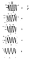
- FIG. 10a shows the coil spring 3 in a relaxed state. This has a length L1.
- the helical spring 3 is shortened axially in a corresponding device 24, which is shown here only schematically, to a desired installation length L2.
- the introduction of force in the device 24 is schematically represented by an arrow F.
- the holding means 4 are fixed to the coil spring 3, wherein it is provided in particular that the holding means 4 are arranged at a distance from the winding ends 5, 6.
- the axial shortening of the helical spring 3 and the fixing by means of the mounting means 4 are shown as separate process steps 10b and 10c.
- the two mentioned method steps are summarized; For example, the axial shortening of the coil spring 3 can take place by means of corresponding tensioning of the bands 4 folded around two axially spaced turns 10.
- step 10d the arrangement 2 of helical spring 3 and holding means 4 is inserted into the desired installation position. Subsequently, the holding means 4 are removed from the coil spring 3. In this case, the last step, the removal of the holding means 4, take place either in the unloaded or axially loaded installation state of the coil spring 3, the latter in FIG. 10e is shown.
- the holding means 4 in fixed to the coil spring 3 state have a substantially rigid length.
- the holding means 4 in the assembled state are not extendable beyond their elastic elongation and also not adjustable.
- the advantage of the arrangement 2 according to the invention of helical spring 3 and holding means 4 can be seen in the fact that the assembly thus formed can already be delivered to customers in an axially shortened length L2. An otherwise necessary process step of biasing the coil spring on site to shorten this to installation length, is eliminated. Overall, this results in a simple assembly, transport, handling and disassembly of the arrangement.
Landscapes
- Engineering & Computer Science (AREA)
- General Engineering & Computer Science (AREA)
- Mechanical Engineering (AREA)
- Springs (AREA)
Applications Claiming Priority (1)
| Application Number | Priority Date | Filing Date | Title |
|---|---|---|---|
| DE102012104408A DE102012104408A1 (de) | 2012-05-22 | 2012-05-22 | Anordnung mit Schraubenfeder und Haltemitteln, Verwendung von Haltemitteln und Verfahren zur Montage von Schraubenfedern |
Publications (3)
| Publication Number | Publication Date |
|---|---|
| EP2667049A2 true EP2667049A2 (fr) | 2013-11-27 |
| EP2667049A3 EP2667049A3 (fr) | 2016-01-06 |
| EP2667049B1 EP2667049B1 (fr) | 2019-02-06 |
Family
ID=48087400
Family Applications (1)
| Application Number | Title | Priority Date | Filing Date |
|---|---|---|---|
| EP13162165.8A Not-in-force EP2667049B1 (fr) | 2012-05-22 | 2013-04-03 | Agencement de ressorts cylindriques et moyens de fixation, utilisation des moyens de fixation et procédé de montage des ressorts cylindriques |
Country Status (2)
| Country | Link |
|---|---|
| EP (1) | EP2667049B1 (fr) |
| DE (1) | DE102012104408A1 (fr) |
Cited By (3)
| Publication number | Priority date | Publication date | Assignee | Title |
|---|---|---|---|---|
| CN108050186A (zh) * | 2017-12-13 | 2018-05-18 | 柳州上丰自动化设备有限公司 | 一种新型弹簧 |
| EA031963B1 (ru) * | 2017-03-20 | 2019-03-29 | Александр Петрович Любавин | Ремень-держатель сжатой пружины |
| CN113021264A (zh) * | 2021-03-11 | 2021-06-25 | 蔚来汽车科技(安徽)有限公司 | 用于弹簧的压装保持装置 |
Families Citing this family (3)
| Publication number | Priority date | Publication date | Assignee | Title |
|---|---|---|---|---|
| DE102015007933B4 (de) * | 2015-06-19 | 2017-06-22 | Tridelta Überspannungsableiter Gmbh | Überspannungsableiter, Verfahren zur Herstellung eines Überspannungsableiters |
| DE102022134977A1 (de) * | 2022-12-29 | 2024-07-04 | RWE Nuclear GmbH | Demontage einer Rohrhalterung mit Feder |
| DE102022134976A1 (de) * | 2022-12-29 | 2024-07-04 | RWE Nuclear GmbH | Demontage einer Rohrhalterung mit Feder |
Citations (2)
| Publication number | Priority date | Publication date | Assignee | Title |
|---|---|---|---|---|
| EP1165331B1 (fr) | 2000-01-31 | 2003-09-03 | INA-Schaeffler KG | Dispositif comportant un ressort a boudins et un palier support pour jambes de force a ressort |
| DE202011100697U1 (de) | 2011-05-13 | 2011-07-15 | Klann-Spezial-Werkzeugbau-Gmbh | Federspanner mit einer Stützplatte und zwei Spindeltrieben |
Family Cites Families (5)
| Publication number | Priority date | Publication date | Assignee | Title |
|---|---|---|---|---|
| US3237919A (en) * | 1961-11-20 | 1966-03-01 | Mitchell Klupt | Coil spring compressor |
| US4442580A (en) * | 1981-04-03 | 1984-04-17 | Dimitrios Antoniadis | Coil spring tool |
| FR2757107B1 (fr) * | 1996-12-12 | 1999-03-12 | Bianchi Mauro Sa | Suspensions de roue de vehicule utilisant un ressort combine a une armature souple destinee a modifier sa courbe de raideur |
| JP4897672B2 (ja) * | 2005-03-31 | 2012-03-14 | 株式会社パイオラックス | スプリング組立体 |
| FR2921864B1 (fr) * | 2007-10-05 | 2017-03-10 | Allevard Rejna Autosuspensions | Procede d'assemblage de jambe de force et jambe de force assemblee selon ce procede |
-
2012
- 2012-05-22 DE DE102012104408A patent/DE102012104408A1/de not_active Ceased
-
2013
- 2013-04-03 EP EP13162165.8A patent/EP2667049B1/fr not_active Not-in-force
Patent Citations (2)
| Publication number | Priority date | Publication date | Assignee | Title |
|---|---|---|---|---|
| EP1165331B1 (fr) | 2000-01-31 | 2003-09-03 | INA-Schaeffler KG | Dispositif comportant un ressort a boudins et un palier support pour jambes de force a ressort |
| DE202011100697U1 (de) | 2011-05-13 | 2011-07-15 | Klann-Spezial-Werkzeugbau-Gmbh | Federspanner mit einer Stützplatte und zwei Spindeltrieben |
Cited By (4)
| Publication number | Priority date | Publication date | Assignee | Title |
|---|---|---|---|---|
| EA031963B1 (ru) * | 2017-03-20 | 2019-03-29 | Александр Петрович Любавин | Ремень-держатель сжатой пружины |
| CN108050186A (zh) * | 2017-12-13 | 2018-05-18 | 柳州上丰自动化设备有限公司 | 一种新型弹簧 |
| CN113021264A (zh) * | 2021-03-11 | 2021-06-25 | 蔚来汽车科技(安徽)有限公司 | 用于弹簧的压装保持装置 |
| EP4063684A1 (fr) * | 2021-03-11 | 2022-09-28 | Nio Technology (Anhui) Co., Ltd | Dispositif de pression et de retenue pour ressort |
Also Published As
| Publication number | Publication date |
|---|---|
| EP2667049B1 (fr) | 2019-02-06 |
| EP2667049A3 (fr) | 2016-01-06 |
| DE102012104408A1 (de) | 2013-11-28 |
Similar Documents
| Publication | Publication Date | Title |
|---|---|---|
| EP2667049B1 (fr) | Agencement de ressorts cylindriques et moyens de fixation, utilisation des moyens de fixation et procédé de montage des ressorts cylindriques | |
| EP2539199B1 (fr) | Protection d'axe d'essieu | |
| DE3327817A1 (de) | Gummi-metall-buchse, insbesondere fuer die lagerung eines stabilisators an einem kraftfahrzeug | |
| EP1031756B1 (fr) | Fixation d'un soufflet roulant d'un ressort pneumatique sur un élément de support | |
| DE10317836A1 (de) | Stabilisatorstangenanordnung für ein Kraftfahrzeug | |
| WO2001056818A1 (fr) | Dispositif comportant un ressort a boudins et un palier support pour jambes de force a ressort | |
| EP1194326B1 (fr) | Mecanisme telescopique | |
| DE102017201016A1 (de) | Sicherheitsgurteinrichtung für ein Fahrzeug | |
| DE202018107343U1 (de) | Zugfederanordnung | |
| DE102011051403B4 (de) | Stützvorrichtung, Federbein umfassend eine solche und Verfahren zum Herstellen eines Stützelements | |
| EP3509908B1 (fr) | Élément de recouvrement pour un moyen d'arrimage ou d'arrêt | |
| DE2242573A1 (de) | Aufpralldaempfende stosstangenbefestigung an kraftfahrzeugen | |
| EP3498504B1 (fr) | Bras de suspension à ressort pour une suspension de roue d'un véhicule automobile | |
| DE4142561C2 (de) | Luftfeder mit einem wulstlosen Luftfederbalg aus elastomerem Werkstoff | |
| DE2708538B2 (de) | Verbindung zwischen den Kettengliedern einer Gleiskette | |
| EP0990811B1 (fr) | Dispositif de soufflet préassemblé pour couvrir des arbres articulés | |
| DE102016012731A1 (de) | Dämpfungskörper für eine obere Auflage | |
| DE102009032919A1 (de) | Federungsanordnung mit einer Blattfeder aus einem Faserverbundwerkstoff | |
| EP0791731A1 (fr) | Elément de conduite flexible pour éléments tubulaires | |
| DE102008059844A1 (de) | Vorrichtung zum Befestigen eines oder mehrerer Behälter an einem Fahrzeugbauteil | |
| WO2016096909A1 (fr) | Dispositif de transmission d'un couple d'un moteur à combustion interne vers un groupe auxiliaire | |
| WO2017207801A1 (fr) | Ensemble ressort à lames et ressort à lames | |
| EP2520822A2 (fr) | Support de ressort avec un ressort de suspension | |
| EP3851616B1 (fr) | Ancre de transport pourvue de bande de maintien | |
| DE102013017978B4 (de) | Druckfeder mit Überlastungsschutz, insbesondere zwischen einem Blattfederende und einem Achskörper eines Lastkraftwagens |
Legal Events
| Date | Code | Title | Description |
|---|---|---|---|
| PUAI | Public reference made under article 153(3) epc to a published international application that has entered the european phase |
Free format text: ORIGINAL CODE: 0009012 |
|
| AK | Designated contracting states |
Kind code of ref document: A2 Designated state(s): AL AT BE BG CH CY CZ DE DK EE ES FI FR GB GR HR HU IE IS IT LI LT LU LV MC MK MT NL NO PL PT RO RS SE SI SK SM TR |
|
| AX | Request for extension of the european patent |
Extension state: BA ME |
|
| PUAL | Search report despatched |
Free format text: ORIGINAL CODE: 0009013 |
|
| AK | Designated contracting states |
Kind code of ref document: A3 Designated state(s): AL AT BE BG CH CY CZ DE DK EE ES FI FR GB GR HR HU IE IS IT LI LT LU LV MC MK MT NL NO PL PT RO RS SE SI SK SM TR |
|
| AX | Request for extension of the european patent |
Extension state: BA ME |
|
| RIC1 | Information provided on ipc code assigned before grant |
Ipc: F16F 1/13 20060101AFI20151201BHEP Ipc: F16F 1/12 20060101ALI20151201BHEP |
|
| 17P | Request for examination filed |
Effective date: 20160318 |
|
| RBV | Designated contracting states (corrected) |
Designated state(s): AL AT BE BG CH CY CZ DE DK EE ES FI FR GB GR HR HU IE IS IT LI LT LU LV MC MK MT NL NO PL PT RO RS SE SI SK SM TR |
|
| GRAP | Despatch of communication of intention to grant a patent |
Free format text: ORIGINAL CODE: EPIDOSNIGR1 |
|
| STAA | Information on the status of an ep patent application or granted ep patent |
Free format text: STATUS: GRANT OF PATENT IS INTENDED |
|
| INTG | Intention to grant announced |
Effective date: 20180827 |
|
| GRAS | Grant fee paid |
Free format text: ORIGINAL CODE: EPIDOSNIGR3 |
|
| GRAA | (expected) grant |
Free format text: ORIGINAL CODE: 0009210 |
|
| STAA | Information on the status of an ep patent application or granted ep patent |
Free format text: STATUS: THE PATENT HAS BEEN GRANTED |
|
| AK | Designated contracting states |
Kind code of ref document: B1 Designated state(s): AL AT BE BG CH CY CZ DE DK EE ES FI FR GB GR HR HU IE IS IT LI LT LU LV MC MK MT NL NO PL PT RO RS SE SI SK SM TR |
|
| REG | Reference to a national code |
Ref country code: GB Ref legal event code: FG4D Free format text: NOT ENGLISH |
|
| REG | Reference to a national code |
Ref country code: CH Ref legal event code: EP Ref country code: AT Ref legal event code: REF Ref document number: 1095107 Country of ref document: AT Kind code of ref document: T Effective date: 20190215 |
|
| REG | Reference to a national code |
Ref country code: IE Ref legal event code: FG4D Free format text: LANGUAGE OF EP DOCUMENT: GERMAN |
|
| REG | Reference to a national code |
Ref country code: DE Ref legal event code: R096 Ref document number: 502013012132 Country of ref document: DE |
|
| REG | Reference to a national code |
Ref country code: NL Ref legal event code: MP Effective date: 20190206 |
|
| REG | Reference to a national code |
Ref country code: LT Ref legal event code: MG4D |
|
| PG25 | Lapsed in a contracting state [announced via postgrant information from national office to epo] |
Ref country code: NO Free format text: LAPSE BECAUSE OF FAILURE TO SUBMIT A TRANSLATION OF THE DESCRIPTION OR TO PAY THE FEE WITHIN THE PRESCRIBED TIME-LIMIT Effective date: 20190506 Ref country code: LT Free format text: LAPSE BECAUSE OF FAILURE TO SUBMIT A TRANSLATION OF THE DESCRIPTION OR TO PAY THE FEE WITHIN THE PRESCRIBED TIME-LIMIT Effective date: 20190206 Ref country code: SE Free format text: LAPSE BECAUSE OF FAILURE TO SUBMIT A TRANSLATION OF THE DESCRIPTION OR TO PAY THE FEE WITHIN THE PRESCRIBED TIME-LIMIT Effective date: 20190206 Ref country code: NL Free format text: LAPSE BECAUSE OF FAILURE TO SUBMIT A TRANSLATION OF THE DESCRIPTION OR TO PAY THE FEE WITHIN THE PRESCRIBED TIME-LIMIT Effective date: 20190206 Ref country code: PT Free format text: LAPSE BECAUSE OF FAILURE TO SUBMIT A TRANSLATION OF THE DESCRIPTION OR TO PAY THE FEE WITHIN THE PRESCRIBED TIME-LIMIT Effective date: 20190606 Ref country code: FI Free format text: LAPSE BECAUSE OF FAILURE TO SUBMIT A TRANSLATION OF THE DESCRIPTION OR TO PAY THE FEE WITHIN THE PRESCRIBED TIME-LIMIT Effective date: 20190206 |
|
| PGFP | Annual fee paid to national office [announced via postgrant information from national office to epo] |
Ref country code: DE Payment date: 20190402 Year of fee payment: 7 |
|
| PG25 | Lapsed in a contracting state [announced via postgrant information from national office to epo] |
Ref country code: RS Free format text: LAPSE BECAUSE OF FAILURE TO SUBMIT A TRANSLATION OF THE DESCRIPTION OR TO PAY THE FEE WITHIN THE PRESCRIBED TIME-LIMIT Effective date: 20190206 Ref country code: HR Free format text: LAPSE BECAUSE OF FAILURE TO SUBMIT A TRANSLATION OF THE DESCRIPTION OR TO PAY THE FEE WITHIN THE PRESCRIBED TIME-LIMIT Effective date: 20190206 Ref country code: LV Free format text: LAPSE BECAUSE OF FAILURE TO SUBMIT A TRANSLATION OF THE DESCRIPTION OR TO PAY THE FEE WITHIN THE PRESCRIBED TIME-LIMIT Effective date: 20190206 Ref country code: BG Free format text: LAPSE BECAUSE OF FAILURE TO SUBMIT A TRANSLATION OF THE DESCRIPTION OR TO PAY THE FEE WITHIN THE PRESCRIBED TIME-LIMIT Effective date: 20190506 Ref country code: IS Free format text: LAPSE BECAUSE OF FAILURE TO SUBMIT A TRANSLATION OF THE DESCRIPTION OR TO PAY THE FEE WITHIN THE PRESCRIBED TIME-LIMIT Effective date: 20190606 Ref country code: GR Free format text: LAPSE BECAUSE OF FAILURE TO SUBMIT A TRANSLATION OF THE DESCRIPTION OR TO PAY THE FEE WITHIN THE PRESCRIBED TIME-LIMIT Effective date: 20190507 |
|
| PG25 | Lapsed in a contracting state [announced via postgrant information from national office to epo] |
Ref country code: EE Free format text: LAPSE BECAUSE OF FAILURE TO SUBMIT A TRANSLATION OF THE DESCRIPTION OR TO PAY THE FEE WITHIN THE PRESCRIBED TIME-LIMIT Effective date: 20190206 Ref country code: DK Free format text: LAPSE BECAUSE OF FAILURE TO SUBMIT A TRANSLATION OF THE DESCRIPTION OR TO PAY THE FEE WITHIN THE PRESCRIBED TIME-LIMIT Effective date: 20190206 Ref country code: AL Free format text: LAPSE BECAUSE OF FAILURE TO SUBMIT A TRANSLATION OF THE DESCRIPTION OR TO PAY THE FEE WITHIN THE PRESCRIBED TIME-LIMIT Effective date: 20190206 Ref country code: SK Free format text: LAPSE BECAUSE OF FAILURE TO SUBMIT A TRANSLATION OF THE DESCRIPTION OR TO PAY THE FEE WITHIN THE PRESCRIBED TIME-LIMIT Effective date: 20190206 Ref country code: CZ Free format text: LAPSE BECAUSE OF FAILURE TO SUBMIT A TRANSLATION OF THE DESCRIPTION OR TO PAY THE FEE WITHIN THE PRESCRIBED TIME-LIMIT Effective date: 20190206 Ref country code: IT Free format text: LAPSE BECAUSE OF FAILURE TO SUBMIT A TRANSLATION OF THE DESCRIPTION OR TO PAY THE FEE WITHIN THE PRESCRIBED TIME-LIMIT Effective date: 20190206 Ref country code: ES Free format text: LAPSE BECAUSE OF FAILURE TO SUBMIT A TRANSLATION OF THE DESCRIPTION OR TO PAY THE FEE WITHIN THE PRESCRIBED TIME-LIMIT Effective date: 20190206 Ref country code: RO Free format text: LAPSE BECAUSE OF FAILURE TO SUBMIT A TRANSLATION OF THE DESCRIPTION OR TO PAY THE FEE WITHIN THE PRESCRIBED TIME-LIMIT Effective date: 20190206 |
|
| REG | Reference to a national code |
Ref country code: DE Ref legal event code: R097 Ref document number: 502013012132 Country of ref document: DE |
|
| PG25 | Lapsed in a contracting state [announced via postgrant information from national office to epo] |
Ref country code: SM Free format text: LAPSE BECAUSE OF FAILURE TO SUBMIT A TRANSLATION OF THE DESCRIPTION OR TO PAY THE FEE WITHIN THE PRESCRIBED TIME-LIMIT Effective date: 20190206 Ref country code: PL Free format text: LAPSE BECAUSE OF FAILURE TO SUBMIT A TRANSLATION OF THE DESCRIPTION OR TO PAY THE FEE WITHIN THE PRESCRIBED TIME-LIMIT Effective date: 20190206 |
|
| REG | Reference to a national code |
Ref country code: CH Ref legal event code: PL |
|
| PLBE | No opposition filed within time limit |
Free format text: ORIGINAL CODE: 0009261 |
|
| STAA | Information on the status of an ep patent application or granted ep patent |
Free format text: STATUS: NO OPPOSITION FILED WITHIN TIME LIMIT |
|
| REG | Reference to a national code |
Ref country code: BE Ref legal event code: MM Effective date: 20190430 |
|
| PG25 | Lapsed in a contracting state [announced via postgrant information from national office to epo] |
Ref country code: MC Free format text: LAPSE BECAUSE OF FAILURE TO SUBMIT A TRANSLATION OF THE DESCRIPTION OR TO PAY THE FEE WITHIN THE PRESCRIBED TIME-LIMIT Effective date: 20190206 Ref country code: LU Free format text: LAPSE BECAUSE OF NON-PAYMENT OF DUE FEES Effective date: 20190403 |
|
| 26N | No opposition filed |
Effective date: 20191107 |
|
| GBPC | Gb: european patent ceased through non-payment of renewal fee |
Effective date: 20190506 |
|
| PG25 | Lapsed in a contracting state [announced via postgrant information from national office to epo] |
Ref country code: LI Free format text: LAPSE BECAUSE OF NON-PAYMENT OF DUE FEES Effective date: 20190430 Ref country code: CH Free format text: LAPSE BECAUSE OF NON-PAYMENT OF DUE FEES Effective date: 20190430 |
|
| PG25 | Lapsed in a contracting state [announced via postgrant information from national office to epo] |
Ref country code: FR Free format text: LAPSE BECAUSE OF NON-PAYMENT OF DUE FEES Effective date: 20190406 Ref country code: BE Free format text: LAPSE BECAUSE OF NON-PAYMENT OF DUE FEES Effective date: 20190430 Ref country code: SI Free format text: LAPSE BECAUSE OF FAILURE TO SUBMIT A TRANSLATION OF THE DESCRIPTION OR TO PAY THE FEE WITHIN THE PRESCRIBED TIME-LIMIT Effective date: 20190206 |
|
| PG25 | Lapsed in a contracting state [announced via postgrant information from national office to epo] |
Ref country code: TR Free format text: LAPSE BECAUSE OF FAILURE TO SUBMIT A TRANSLATION OF THE DESCRIPTION OR TO PAY THE FEE WITHIN THE PRESCRIBED TIME-LIMIT Effective date: 20190206 |
|
| PG25 | Lapsed in a contracting state [announced via postgrant information from national office to epo] |
Ref country code: IE Free format text: LAPSE BECAUSE OF NON-PAYMENT OF DUE FEES Effective date: 20190403 Ref country code: GB Free format text: LAPSE BECAUSE OF NON-PAYMENT OF DUE FEES Effective date: 20190506 |
|
| REG | Reference to a national code |
Ref country code: AT Ref legal event code: MM01 Ref document number: 1095107 Country of ref document: AT Kind code of ref document: T Effective date: 20190403 |
|
| REG | Reference to a national code |
Ref country code: DE Ref legal event code: R119 Ref document number: 502013012132 Country of ref document: DE |
|
| PG25 | Lapsed in a contracting state [announced via postgrant information from national office to epo] |
Ref country code: AT Free format text: LAPSE BECAUSE OF NON-PAYMENT OF DUE FEES Effective date: 20190403 |
|
| PG25 | Lapsed in a contracting state [announced via postgrant information from national office to epo] |
Ref country code: DE Free format text: LAPSE BECAUSE OF NON-PAYMENT OF DUE FEES Effective date: 20201103 |
|
| PG25 | Lapsed in a contracting state [announced via postgrant information from national office to epo] |
Ref country code: CY Free format text: LAPSE BECAUSE OF FAILURE TO SUBMIT A TRANSLATION OF THE DESCRIPTION OR TO PAY THE FEE WITHIN THE PRESCRIBED TIME-LIMIT Effective date: 20190206 |
|
| PG25 | Lapsed in a contracting state [announced via postgrant information from national office to epo] |
Ref country code: HU Free format text: LAPSE BECAUSE OF FAILURE TO SUBMIT A TRANSLATION OF THE DESCRIPTION OR TO PAY THE FEE WITHIN THE PRESCRIBED TIME-LIMIT; INVALID AB INITIO Effective date: 20130403 Ref country code: MT Free format text: LAPSE BECAUSE OF FAILURE TO SUBMIT A TRANSLATION OF THE DESCRIPTION OR TO PAY THE FEE WITHIN THE PRESCRIBED TIME-LIMIT Effective date: 20190206 |
|
| PG25 | Lapsed in a contracting state [announced via postgrant information from national office to epo] |
Ref country code: MK Free format text: LAPSE BECAUSE OF FAILURE TO SUBMIT A TRANSLATION OF THE DESCRIPTION OR TO PAY THE FEE WITHIN THE PRESCRIBED TIME-LIMIT Effective date: 20190206 |