EP2668387B1 - Elément de mélange pour unités de turbine à gaz comportant une recirculation des gaz de combustion - Google Patents
Elément de mélange pour unités de turbine à gaz comportant une recirculation des gaz de combustion Download PDFInfo
- Publication number
- EP2668387B1 EP2668387B1 EP12700512.2A EP12700512A EP2668387B1 EP 2668387 B1 EP2668387 B1 EP 2668387B1 EP 12700512 A EP12700512 A EP 12700512A EP 2668387 B1 EP2668387 B1 EP 2668387B1
- Authority
- EP
- European Patent Office
- Prior art keywords
- mixing
- airflow
- gas turbine
- flow path
- ducts
- Prior art date
- Legal status (The legal status is an assumption and is not a legal conclusion. Google has not performed a legal analysis and makes no representation as to the accuracy of the status listed.)
- Active
Links
Images


Classifications
-
- F—MECHANICAL ENGINEERING; LIGHTING; HEATING; WEAPONS; BLASTING
- F02—COMBUSTION ENGINES; HOT-GAS OR COMBUSTION-PRODUCT ENGINE PLANTS
- F02C—GAS-TURBINE PLANTS; AIR INTAKES FOR JET-PROPULSION PLANTS; CONTROLLING FUEL SUPPLY IN AIR-BREATHING JET-PROPULSION PLANTS
- F02C7/00—Features, components parts, details or accessories, not provided for in, or of interest apart form groups F02C1/00 - F02C6/00; Air intakes for jet-propulsion plants
- F02C7/04—Air intakes for gas-turbine plants or jet-propulsion plants
-
- B—PERFORMING OPERATIONS; TRANSPORTING
- B01—PHYSICAL OR CHEMICAL PROCESSES OR APPARATUS IN GENERAL
- B01F—MIXING, e.g. DISSOLVING, EMULSIFYING OR DISPERSING
- B01F23/00—Mixing according to the phases to be mixed, e.g. dispersing or emulsifying
- B01F23/10—Mixing gases with gases
-
- B—PERFORMING OPERATIONS; TRANSPORTING
- B01—PHYSICAL OR CHEMICAL PROCESSES OR APPARATUS IN GENERAL
- B01F—MIXING, e.g. DISSOLVING, EMULSIFYING OR DISPERSING
- B01F25/00—Flow mixers; Mixers for falling materials, e.g. solid particles
- B01F25/30—Injector mixers
- B01F25/31—Injector mixers in conduits or tubes through which the main component flows
- B01F25/313—Injector mixers in conduits or tubes through which the main component flows wherein additional components are introduced in the centre of the conduit
- B01F25/3132—Injector mixers in conduits or tubes through which the main component flows wherein additional components are introduced in the centre of the conduit by using two or more injector devices
- B01F25/31322—Injector mixers in conduits or tubes through which the main component flows wherein additional components are introduced in the centre of the conduit by using two or more injector devices used simultaneously
-
- B—PERFORMING OPERATIONS; TRANSPORTING
- B01—PHYSICAL OR CHEMICAL PROCESSES OR APPARATUS IN GENERAL
- B01F—MIXING, e.g. DISSOLVING, EMULSIFYING OR DISPERSING
- B01F25/00—Flow mixers; Mixers for falling materials, e.g. solid particles
- B01F25/30—Injector mixers
- B01F25/31—Injector mixers in conduits or tubes through which the main component flows
- B01F25/313—Injector mixers in conduits or tubes through which the main component flows wherein additional components are introduced in the centre of the conduit
- B01F25/3133—Injector mixers in conduits or tubes through which the main component flows wherein additional components are introduced in the centre of the conduit characterised by the specific design of the injector
- B01F25/31331—Perforated, multi-opening, with a plurality of holes
-
- F—MECHANICAL ENGINEERING; LIGHTING; HEATING; WEAPONS; BLASTING
- F02—COMBUSTION ENGINES; HOT-GAS OR COMBUSTION-PRODUCT ENGINE PLANTS
- F02C—GAS-TURBINE PLANTS; AIR INTAKES FOR JET-PROPULSION PLANTS; CONTROLLING FUEL SUPPLY IN AIR-BREATHING JET-PROPULSION PLANTS
- F02C3/00—Gas-turbine plants characterised by the use of combustion products as the working fluid
- F02C3/34—Gas-turbine plants characterised by the use of combustion products as the working fluid with recycling of part of the working fluid, i.e. semi-closed cycles with combustion products in the closed part of the cycle
-
- F—MECHANICAL ENGINEERING; LIGHTING; HEATING; WEAPONS; BLASTING
- F02—COMBUSTION ENGINES; HOT-GAS OR COMBUSTION-PRODUCT ENGINE PLANTS
- F02C—GAS-TURBINE PLANTS; AIR INTAKES FOR JET-PROPULSION PLANTS; CONTROLLING FUEL SUPPLY IN AIR-BREATHING JET-PROPULSION PLANTS
- F02C7/00—Features, components parts, details or accessories, not provided for in, or of interest apart form groups F02C1/00 - F02C6/00; Air intakes for jet-propulsion plants
- F02C7/04—Air intakes for gas-turbine plants or jet-propulsion plants
- F02C7/057—Control or regulation
-
- F—MECHANICAL ENGINEERING; LIGHTING; HEATING; WEAPONS; BLASTING
- F05—INDEXING SCHEMES RELATING TO ENGINES OR PUMPS IN VARIOUS SUBCLASSES OF CLASSES F01-F04
- F05D—INDEXING SCHEME FOR ASPECTS RELATING TO NON-POSITIVE-DISPLACEMENT MACHINES OR ENGINES, GAS-TURBINES OR JET-PROPULSION PLANTS
- F05D2260/00—Function
- F05D2260/20—Heat transfer, e.g. cooling
- F05D2260/221—Improvement of heat transfer
- F05D2260/2212—Improvement of heat transfer by creating turbulence
-
- F—MECHANICAL ENGINEERING; LIGHTING; HEATING; WEAPONS; BLASTING
- F05—INDEXING SCHEMES RELATING TO ENGINES OR PUMPS IN VARIOUS SUBCLASSES OF CLASSES F01-F04
- F05D—INDEXING SCHEME FOR ASPECTS RELATING TO NON-POSITIVE-DISPLACEMENT MACHINES OR ENGINES, GAS-TURBINES OR JET-PROPULSION PLANTS
- F05D2260/00—Function
- F05D2260/60—Fluid transfer
- F05D2260/61—Removal of CO2
-
- Y—GENERAL TAGGING OF NEW TECHNOLOGICAL DEVELOPMENTS; GENERAL TAGGING OF CROSS-SECTIONAL TECHNOLOGIES SPANNING OVER SEVERAL SECTIONS OF THE IPC; TECHNICAL SUBJECTS COVERED BY FORMER USPC CROSS-REFERENCE ART COLLECTIONS [XRACs] AND DIGESTS
- Y02—TECHNOLOGIES OR APPLICATIONS FOR MITIGATION OR ADAPTATION AGAINST CLIMATE CHANGE
- Y02E—REDUCTION OF GREENHOUSE GAS [GHG] EMISSIONS, RELATED TO ENERGY GENERATION, TRANSMISSION OR DISTRIBUTION
- Y02E20/00—Combustion technologies with mitigation potential
- Y02E20/16—Combined cycle power plant [CCPP], or combined cycle gas turbine [CCGT]
Definitions
- the present invention relates to the field of fluegas recirculation in gas turbines, specifically to elements for mixing fluegas with ambient air upstream of the compressor.
- Fluegas recirculation is beneficial for the carbon dioxide capture process because both the concentration of carbon dioxide is increased and the overall mass flow to the carbon dioxide capture unit is reduced.
- a gas turbine with a device for mixing recirculated flue gas with fresh air is known from the CH 701 235 A1 .
- the device separates spaces in the flow channel into a first region for the recirculated exhaust gas and a second regions for the fresh intake air. The two regions terminate downstream in a mixing zone.
- the CH 701 236 A1 describes a silencer for an air intake of a gas turbine with flue gas recirculation, which comprises elements for the admixing of recirculated flue gases into the inlet stream of the gas turbine.
- the carbon dioxide enriched fluegas has to be mixed with ambient air and then supplied to the compressor inlet of the gas turbine.
- the compressor delivers this carbon dioxide containing mixture to the combustor and into the secondary cooling systems of the gas turbines.
- the recirculation of fluegas lowers in total the amount of oxygen which is supplied to the combustion process.
- the remaining oxygen concentration after the combustion process is the limiting parameter for the amount of recirculated fluegas.
- the fluegas ratio defined as the ratio of recirculated fluegas and the gas turbine exhaust mass flow
- UHC unburnt hydrocarbons
- the control of the fluegas recirculation ratio is essential to allow for safe gas turbine operation.
- a robust design of the mixer is critical to ensure good mixing quality over a wide range of fuel gas ratios and load parameters of the turbine.
- the recirculated fluegas has to be evenly mixed with the fresh air upstream of the compressor.
- the gist of the present invention is to install a mixer device in the intake of the gas turbine, wherein this mixer device can for example be upstream or downstream of the filter and/or the silencer in the intake.
- the mixer can for example be a finger type mixer extending from one single sidewall of the intake unit into the flow path defined thereby. Plates and/or guide vanes can be used to improve mixing in the pipes of the mixer, at the outlet of the mixer or downstream of the outlet of the mixer.
- the present invention relates to a gas turbine unit with fluegas recirculation according to claim 1 and comprising, inter alia, a compressor having an inlet and an intake section upstream of the inlet of the compressor, the intake section comprising at least one section with a flow path defined by sidewalls in which the fresh airflow of the intake air is flowing along a principal airflow direction, and comprising at least one mixing duct or mixing finger extending into the flow path from at least one sidewall.
- This mixing duct preferably comprises an intake at said at least one sidewall for receiving recirculated fluegas, as well as at least one outlet opening distanced from said sidewall for blowing recirculated fluegas out of the mixing duct into the airflow, preferably not too close to a wall region thereof but in a more central region thereof.
- the mixing duct is attached to a single sidewall only (mixing finger) and freely extends into the flow path.
- the at least one outlet opening is located in a tip region of the mixing duct or in proximity thereto, or distributed along the length of the duct.
- At least two, three, four, or at least five mixing ducts can be arranged in a row, preferably adjacent to each other, said row preferably being aligned essentially along the airflow direction, the most upstream mixing duct defining a leading edge of the row.
- the mixing ducts of such a row all have different lengths of extension into the flow path, and preferably the most upstream mixing duct extends most into the flow path, the most downstream mixing duct extends the least into the flow path, and mixing ducts between are of successively decreasing length as a function of their downstream position, wherein further preferably the lengths are regularly decreasing along the row.
- At least two, or at least three, or at least four rows/mixing ducts in a direction perpendicular to the airflow direction can be arranged distanced from each other, preferably equally distanced from each other, in the flow path.
- at least two or at least three rows/mixing ducts can be arranged distanced from each other, in the flow path.
- the at least one mixing duct can extend into flow path with its axis essentially perpendicular to airflow direction in the flow path. It can however also be inclined thereto, and for example the leading edge thereof can have a bent or curved shape depending inter alia, on the aerodynamics in the flow path. Preferentially in the flow path the airflow direction is essentially parallel to the sidewalls.
- the mixing duct can be of tubular design. Alternatively it may comprise or be formed by four, preferably pairwise parallel walls defining the duct.
- the outlet opening can open in a direction essentially perpendicular to the direction of the airflow or in a direction essentially parallel and concurrent to the direction of the airflow (blowing out of the trailing edge).
- the at least one outlet opening can open in a direction essentially perpendicular to the direction of the airflow and essentially perpendicular to the axis of the mixing duct (lateral blowing out), wherein preferably two outlet openings are provided for each mixing duct blowing recirculated fluegas in opposite directions into the airflow in the flow path.
- At least one, rounded or straight guide vane can be located, wherein this guide vane can for example be located essentially at half height of the total height of the outlet opening in the direction along the axis of the mixing duct.
- the at least one outlet opening opens in a direction essentially perpendicular to the direction of the airflow and essentially parallel to the axis of the mixing duct, and a mixing element, preferably an impingement plate, is located downstream, with respect to the flow direction of the fluegas, of the outlet opening, preferably arranged essentially perpendicularly to the flow direction of the fluegas and parallel to the airflow direction.
- a mixing element preferably an impingement plate
- the mixing ducts are arranged in a region where the flow path is defined by four pairwise parallel sidewalls, and upstream and/or downstream of the mixing duct or of the row of mixing ducts a silencer and/or a filter is arranged in that region or essentially just upstream and/or downstream of that region.
- the mixing duct or in case of a row of mixing ducts the most upstream located mixing duct comprises an aerodynamically optimised leading edge, for example a rounded leading edge. It is also possible to locate turbulators upstream of the openings on the outside of the mixing ducts to initiate turbulences somewhat upstream of the location where the fluegas is introduced into the airflow to further increase the mixing quality.
- a triangular row of mixing ducts showing an excellent mixing property.
- at least two, or at least three, or at least four, or at least five mixing ducts are arranged in a row, adjacent to each other, said row being alignment essentially along the airflow direction, the most upstream mixing duct defining a (preferably rounded) leading edge of the row, wherein the mixing ducts all have different lengths of extension into the flow path, and wherein the most upstream mixing duct extends most into the flow path, the most downstream mixing duct extending least into the flow path, and mixing ducts between being of successively and preferably regularly decreasing length as a function of their downstream position, wherein the trailing edge of the row is defined by an inclined trailing edge wall and wherein on each lateral side of the row triangular outlet openings open in a direction essentially perpendicular to the direction of the airflow and essentially perpendicular to the axis of the mixing duct.
- the present invention furthermore relates to a gas turbine, preferably combined cycle gas turbine, with an intake section as outlined above.
- the present invention relates to a plant with flue gas recirculation in combination with post-combustion carbon dioxide capture.
- the present invention relates to a method for recirculating fluegas to the intake of a gas turbine unit, preferably of a combined cycle, wherein an intake section as outlined above is used for mixing fresh ambient air with recirculated fluegas.
- flow control elements controlled based on a mass flow measurement in the recirculation line and/or based on a measurement of the composition of the mixed intake air upstream of the compressor, and/or based on a measurement of the combustion quality, are provided in the mixing ducts or upstream of the mixing ducts, are used for controlling the mass flow of recirculated fluegas.
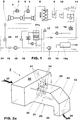
- FIG. 1 shows a general schematic set up of a combined cycle power plant with flue gas recirculation.
- a compressor 1 intake air is compressed and introduced to a first combustor 4, supplied with fuel 3, and the resulting combustion air passes a high pressure turbine 5, downstream of which a second combustor 6 is located, downstream of which in a low pressure turbine 7 the exhaust gases are expanded as much as possible.
- a heat recovery steam generator 8 Downstream of the low pressure turbine 7 a heat recovery steam generator 8 is located by means of which, using the heat in the exhaust gases, steam is generated for driving steam turbines.
- the steam is expanded in a first stage in a high pressure steam turbine 9, followed by an intermediate pressure steam turbine 10 and subsequent to this by a low pressure steam turbine 11, where usually means are provided for by-passing the low pressure steam turbine 11.
- a condenser 12 Downstream of the low pressure steam turbine 11 a condenser 12 condenses the steam to water, which is subsequently pumped by a pump 13 into the heat recovery steam generator unit 8, where it is converted in counter flow to the flow of the exhaust gases to steam again.
- the steam cycle is an essentially closed cycle.
- the exhaust gases Downstream of the heat recovery steam generator unit 8 the exhaust gases, now cooled down to a certain extent, usually pass a diverter 17, where depending on the mode of operation a fraction of the exhaust gases or the totality thereof can be guided to a stack 14 or to a downstream flue gas recirculation system and/or carbon capture system.
- the fraction guided to the flue gas recirculation system usually first passes a direct contact cooler 21a, downstream of this a diverter 17 is provided which, again depending on the mode of operation and specific parameters measured in the unit, a fraction of the exhaust gases is fed to the carbon capture unit, and the other fraction is recirculated in the actual flue gas recirculation piping, which usually also comprises at least one blower 15 as well as a mass flow measurement device 16 in order to control, for the reasons outlined above, the amount of recirculated flue gas in order to keep the combustion conditions in an optimum window.
- these exhaust gases are mixed with ambient air in a mixer 20 which is typically located upstream of the intake housing which is essentially adjacent and upstream of the intake of the compressor 1.
- the direct contact cooler 21a comprises a water spray, which is injected into the flue gas. The water droplets are collected and re-cooled before they are re- injected.
- the fraction of the exhaust gases not recirculated and not specifically used in the flue gas recirculation system 18 are introduced into the carbon capture system 19, if necessary assisted by a blower 15, where in a carbon dioxide absorption unit 19a the carbon dioxide is extracted from the gases and taken out of the system and the remaining gas is fed to a stack 14.
- the present invention pertains to a specific device for mixing re-circulated flue gas with newly aspired ambient air 21, and the idea is to locate the corresponding mixing device in the actual intake section or intake housing 2 upstream of the compressor inlet.
- Such an intake housing 2 usually comprises a wide aspiration section 25 into which the ambient air flow 27 is flowing. Downstream of this wide aspiration section 25 or within this wide aspiration section 25, typically the flow cross section reduces and is followed by a typically horizontal section 22 of constant flow cross section. Downstream of this section 22 there is typically provided a bent section 24 diverting the airflow to a vertical direction and into a vertical section 23 of the intake housing so that the airflow 26 can enter the intake of the compressor 1, and can be compressed in the compressor 1.
- mixing ducts 32 are located in section 22 in the form of a multitude of fingerlike elements protruding from one of the side walls of the section 22 into the flow path 31, typically in a direction essentially perpendicular to the airflow direction 33 in the section 22.
- the mixing ducts 32 are mounted on one of the side walls (or on several of the side walls), and where they are fixed to the side walls there is provided an inlet 34 for the intake of re-circulated flue gas 41.
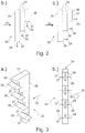
- Figure 2b illustrates a first embodiment of such mixing ducts.
- a row of three mixing ducts 32 in the form of tubular elements with rectangular or square cross section are arranged adjacent to each other.
- the one located most upstream is the longest one, therefore penetrates the most into the flow path 31, and it also forms the leading edge 35 of the row as the subsequent mixing ducts are arranged in a downstream direction thereof.
- the mixing ducts are of regularly decreasing lengths such that the mixing duct located most downstream is the shortest one and penetrates the least into the flow path 31, and essentially forms the trailing edge 36 of the row of mixing ducts.
- each mixing duct provides for a structure where, as at the end of each mixing duct there is an opening 37 through which flue gas taken in via inlets 34, is blown out as illustrated with the arrows 39, and introduces the re-circulated flue gas in a distributed manner over the flow cross section of the airflow 33.
- FIG. 2c An alternative embodiment is illustrated in Figure 2c .
- the tubular elements 32 are closed towards the bottom but on each tip portion on the corresponding trailing side of each mixing duct there are provided outlet openings 37 through which the flue gas exits the mixing ducts essentially in a direction parallel to the airflow direction 33.
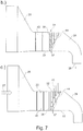
- FIG 3 yet another embedment of a mixing duct 32 is illustrated.
- the mixing duct is of a stepped design and at each step there is provided an outlet 37 blowing flue gas in a direction similar to the one as illustrated in Figure 2b into the airflow.
- the airflow 39 right downstream of the corresponding opening 37 impinges onto an impingement plate 38 which is arranged essentially perpendicular to the direction of the airflow 39 and in a direction parallel to the airflow 33 of the ambient air flowing in the flow path 31.
- impingement plates 38 are mounted on trailing edge side walls of the mixing duct 32.
- the impingement plates 38 in this case laterally on both sides protrude beyond the side walls of the mixing duct, however it is also possible that the impingement plates 38 do not extend beyond the side walls.
- the mixing ducts 32 can be it in a row as illustrated in Figure 2 or structured with several openings 37 distributed along their length as illustrated in Figure 3 , can be built of metal sheet elements. They can also be built of tubular pipe-like elements. In order provide as little resistance to the airflow 33 at the leading edge 35 as possible, as illustrated in Figure 3 , this leading edge 35 is preferably rounded or can have a sharp leading edge. Preferably a flat leading edge with a surface essentially perpendicular to the direction 33 should be avoided.
- the leading edge 35 is normally straight in a direction parallel to the axis of the duct as illustrated in Figure 3c . It is however also possible, depending on the flow circumstances in the flow path 31, to have a shaped leading edge, as for example illustrated in Figure 3d .
- the mixing ducts, arranged in rows can be, as illustrated in Figure 2a , located in a series distanced from each other in a direction perpendicular to the flow direction 33. As illustrated in Figure 3e , it is also possible to have several mixing ducts or rows of mixing ducts arranged following each other in the direction 33, so to have an upstream mixing duct 32 or row of mixing ducts 32, and a downstream mixing duct 32 or row of mixing ducts.
- Each of these mixing ducts can be supplied with re-circulated flue gas with individual ducts 45 and 46, as illustrated in Figure 3e , or by using the same duct coupled to both rows.
- the arrangement of mixing ducts is such that two upstream mixing ducts 32 are located laterally displaced with each other by a long distance, so close to the side walls of the section 22, in the flow path and are supplied with flue gas via duct 45. Downstream of this pair of mixing ducts there is provided a second group of mixing ducts 32, also displaced in a direction perpendicular to the airflow direction 33 but closer to each other so essentially filling the gap between the two upstream mixing ducts.
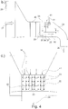
- FIG. 4 Yet another embodiment is illustrated in Figure 4 .
- a silencer 40 downstream of the wide aspiration section 25 there is first located a silencer 40.
- a filter may also be located within section 25.
- each row comprises in this case four mixing ducts of regularly decreasing lengths in a downstream direction.
- each of the mixing ducts in its terminal tip portion, comprises a bottom wall and at both lateral side a lateral opening 37 is provided through which the flue gas 41, as illustrated in Figure 4b , passing through the tubular section of each mixing duct, is then blown out in a direction perpendicular to the flow direction 33, essentially in horizontal direction, as illustrated in Figure 4c .
- the flue gas introduced into the airflow 33 is well distributed over the flow cross section thereof, and this in a vertical direction, as illustrated in 4c, and in horinzontal direction, as illustrated in Figure 4d , but also the mixing introduction takes place over a certain length of the flow path, as one can also see in Figure 4d .
- FIG. 5a Yet another embodiment is shown in Figure 5a .
- the same structure of sixteen mixing ducts arranged in four laterally displaced groups of four mixing ducts each is provided as in Figure 4 .
- the lateral openings 37 provided on each side of each mixing duct in the tip portion thereof with a height h as illustrated in Figure 4b is provided with a rounded guide vane 42, the function of which is best illustrated by Figure 5b .
- These rounded guide vanes make sure that the flue gas 41 passing through the channel of the mixing duct 32 in the region of the lateral openings 37 is exiting through these openings in a well distributed manner so not only under high speed and high pressure in the bottom region thereof but also in the top region thereof. This leads to a lower pressure loss in the mixing device and to an even more homogenous distribution and mixing.
- Figure 6 shows a similar embodiment, in this case however, the guide vanes are not rounded but are provided as straight plates arranged essentially perpendicular to the main axis direction of the respective mixing ducts.
- the vanes are typically arranged in or very close to the actual opening 27.
- the height of the vane is preferably chosen so as to be essentially at half height of the total height h of the opening 37.
- the width of the corresponding vane is preferably chosen to be about one fourth of the total lateral width of the mixing duct, so that one half of the airflow 41 is so to speak captured by the guide vanes and the other half can pass between them and exit via the part of the opening 37 located below the vane 42/43.
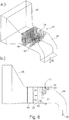
- FIG. 7 A final embodiment is shown in figure 7 .
- 20 mixing ducts are arranged in four groups of five mixing ducts each are of triangular shape.
- the trailing edge of this triangular group is formed by an inclined trailing edge wall 44. Due to this trailing edge wall, which is basically attached to a structure similar to the one illustrated in Figure 2b , leads to triangularly shaped openings 37, as can be best viewed in Figures 7b and c.
Landscapes
- Engineering & Computer Science (AREA)
- Chemical & Material Sciences (AREA)
- Combustion & Propulsion (AREA)
- Mechanical Engineering (AREA)
- General Engineering & Computer Science (AREA)
- Chemical Kinetics & Catalysis (AREA)
- Life Sciences & Earth Sciences (AREA)
- Sustainable Development (AREA)
- Engine Equipment That Uses Special Cycles (AREA)
- Accessories For Mixers (AREA)
- Treating Waste Gases (AREA)
Claims (13)
- Unité de turbine à gaz (1 à 7) avec une recirculation de gaz de combustion comprenant un compresseur (1) comportant une entrée et une section d'admission (2) en amont de l'entrée du compresseur (1), la section d'admission (2) comprenant au moins une section (22) avec un trajet d'écoulement (31) défini par des parois latérales (28 à 30) dans lequel l'écoulement d'air frais de l'air d'admission s'écoule le long d'une direction d'écoulement d'air principale (33), comprenant au moins une conduite de mélange (32) s'étendant dans le trajet d'écoulement (31) à partir d'au moins une paroi latérale (28 à 30), ladite conduite de mélange (32) comprenant un orifice d'admission (34) au niveau de ladite au moins une paroi latérale (28 à 30) pour recevoir le gaz de combustion de recirculation (41), comprenant également au moins une ouverture de sortie (37) à distance de ladite paroi latérale (28 à 30) pour souffler le gaz de combustion de recirculation (41) hors de la conduite de mélange (32) dans l'écoulement d'air, où au moins deux, ou au moins trois, ou au moins quatre, ou au moins cinq conduites de mélange (32) sont agencées en une rangée, adjacentes les unes aux autres, caractérisée en ce que ladite rangée est essentiellement en alignement le long de la direction d'écoulement d'air (33), la conduite de mélange (32) la plus en amont définissant un bord avant de la rangée, où les conduites de mélange (32) ont toutes différentes longueurs d'extension dans le trajet d'écoulement (31), et où la conduite de mélange (32) la plus en amont s'étend le plus dans le trajet d'écoulement (31), la conduite de mélange (32) la plus en aval s'étendant le moins dans le trajet d'écoulement (31), et les conduites de mélange (32) entre celles-ci étant de longueurs successivement décroissantes en fonction de leur position en aval.
- Unité de turbine à gaz selon la revendication 1, dans laquelle la conduite de mélange (32) est attachée à une seule paroi latérale (22) et s'étend librement dans le trajet d'écoulement (31), et dans laquelle au moins une ouverture de sortie (37) est située dans une région d'extrémité de la conduite de mélange (32).
- Unité de turbine à gaz selon la revendication 1, dans laquelle, le long d'une direction perpendiculaire à la direction d'écoulement d'air (33), au moins deux, ou au moins trois, ou au moins quatre rangées sont agencées à distance les unes des autres dans le trajet d'écoulement, et/ou dans laquelle, le long de la direction d'écoulement d'air (33), au moins deux ou au moins trois rangées sont agencées à distance les unes des autres, dans le trajet d'écoulement.
- Unité de turbine à gaz selon l'une quelconque des revendications précédentes, dans laquelle ladite au moins une conduite de mélange (32) ou la rangée de conduites de mélange, s'étend dans le trajet d'écoulement (31) avec son axe essentiellement perpendiculaire à la direction d'écoulement d'air (33) dans le trajet d'écoulement (31).
- Unité de turbine à gaz selon l'une quelconque des revendications précédentes, dans laquelle la conduite de mélange (32) comprend quatre parois définissant la conduite, et dans laquelle l'ouverture de sortie (37) s'ouvre dans une direction essentiellement perpendiculaire à la direction de l'écoulement d'air (33) ou dans une direction essentiellement parallèle et concourante à la direction de l'écoulement d'air (33).
- Unité de turbine à gaz selon l'une quelconque des revendications précédentes, dans laquelle ladite au moins une ouverture de sortie (37) s'ouvre dans une direction essentiellement perpendiculaire à la direction de l'écoulement d'air (33) et essentiellement perpendiculaire à l'axe de la conduite de mélange (32).
- Unité de turbine à gaz selon la revendication 6, dans laquelle, dans ladite au moins une ouverture de sortie (37) ou dans la région de ladite au moins une ouverture de sortie (37), au moins une aube de guidage arrondie ou droite (42, 43) est située.
- Unité de turbine à gaz selon l'une quelconque des revendications précédentes, dans laquelle ladite au moins une ouverture de sortie (37) s'ouvre dans une direction essentiellement perpendiculaire à la direction de l'écoulement d'air (33) et essentiellement parallèle à l'axe de la conduite de mélange (32), et dans laquelle un élément de mélange est situé en aval, par rapport à la direction d'écoulement du gaz de combustion, de l'ouverture de sortie (37).
- Unité de turbine à gaz selon l'une quelconque des revendications précédentes, dans laquelle les conduites de mélange (32) sont agencées dans une région (22) où le trajet d'écoulement (31) est défini par quatre parois latérales parallèles (28 à 30) par paires, et dans laquelle, en amont et/ou en aval de la conduite de mélange (32) ou de la rangée de conduites de mélange (32), un silencieux et/ou un filtre sont agencés dans cette région (22) ou essentiellement juste en amont et/ou en aval cette région (22).
- Unité de turbine à gaz selon l'une quelconque des revendications précédentes, dans laquelle la conduite de mélange (32) ou, dans le cas d'une rangée de conduites de mélange (32), la conduite de mélange située la plus en amont (32) comprend un bord avant arrondi.
- Unité de turbine à gaz selon l'une quelconque des revendications précédentes,
dans laquelle le bord arrière de la rangée est défini par une paroi de bord arrière inclinée (44), et dans laquelle, sur chaque côté latéral de la rangée, des ouvertures de sortie triangulaires (37) s'ouvrent dans une direction essentiellement perpendiculaire à la direction de l'écoulement d'air (33) et essentiellement perpendiculaire à l'axe de la conduite de mélange (32). - Procédé pour faire recirculer un gaz de combustion vers l'orifice d'admission d'une unité de turbine à gaz selon l'une quelconque des revendications 1 à 11 précédentes, où la section d'admission est utilisée pour mélanger l'air ambiant frais avec le gaz de combustion de recirculation.
- Procédé selon la revendication 12, où des éléments de commande d'écoulement, commandés sur la base d'une mesure de débit massique dans la conduite de recirculation et/ou sur la base d'une mesure de la composition de l'air d'admission mélangé en amont du compresseur, et/ou sur la base d'une mesure de la qualité de combustion, prévus dans les conduites de mélange (32) ou en amont des conduites de mélange, sont utilisés pour commander le débit massique du gaz de combustion de recirculation.
Applications Claiming Priority (2)
| Application Number | Priority Date | Filing Date | Title |
|---|---|---|---|
| CH1152011 | 2011-01-24 | ||
| PCT/EP2012/050964 WO2012101087A1 (fr) | 2011-01-24 | 2012-01-23 | Elément de mélange pour unités de turbine à gaz comportant une recirculation des gaz de combustion |
Publications (2)
| Publication Number | Publication Date |
|---|---|
| EP2668387A1 EP2668387A1 (fr) | 2013-12-04 |
| EP2668387B1 true EP2668387B1 (fr) | 2019-03-27 |
Family
ID=43936485
Family Applications (1)
| Application Number | Title | Priority Date | Filing Date |
|---|---|---|---|
| EP12700512.2A Active EP2668387B1 (fr) | 2011-01-24 | 2012-01-23 | Elément de mélange pour unités de turbine à gaz comportant une recirculation des gaz de combustion |
Country Status (8)
| Country | Link |
|---|---|
| US (1) | US9453460B2 (fr) |
| EP (1) | EP2668387B1 (fr) |
| JP (1) | JP5788024B2 (fr) |
| KR (1) | KR101574981B1 (fr) |
| CN (1) | CN103328786B (fr) |
| CA (1) | CA2824710C (fr) |
| RU (1) | RU2573089C2 (fr) |
| WO (1) | WO2012101087A1 (fr) |
Families Citing this family (22)
| Publication number | Priority date | Publication date | Assignee | Title |
|---|---|---|---|---|
| EP2642097A1 (fr) * | 2012-03-21 | 2013-09-25 | Alstom Technology Ltd | Procédé de fonctionnement d'une turbine à gaz et turbine à gaz destinée à l'exécution du procédé |
| US20130269358A1 (en) * | 2012-04-12 | 2013-10-17 | General Electric Company | Methods, systems and apparatus relating to reheat combustion turbine engines with exhaust gas recirculation |
| EP2837795B1 (fr) | 2013-08-14 | 2019-05-01 | Ansaldo Energia IP UK Limited | Agencement d'admission amélioré dans une centrale électrique à turbine à gaz |
| EP2837794A1 (fr) * | 2013-08-14 | 2015-02-18 | Alstom Technology Ltd | Agencement d'admission d'air amélioré dans une centrale électrique à turbine à gaz |
| KR101485020B1 (ko) * | 2013-12-12 | 2015-01-29 | 연세대학교 산학협력단 | 초임계유체 냉각 가스터빈 장치 |
| EP3123011A1 (fr) * | 2014-03-26 | 2017-02-01 | Exxonmobil Upstream Research Company | Système et procédé pour le conditionnement de gaz d'échappement recyclés |
| JP6522370B2 (ja) * | 2015-02-26 | 2019-05-29 | 三菱日立パワーシステムズ株式会社 | 放水ノズル及び混合槽 |
| RU2587511C1 (ru) * | 2015-03-10 | 2016-06-20 | Публичное акционерное общество Научно-производственное объединение "Искра" | Воздухоочистительное устройство |
| EA036299B1 (ru) | 2015-09-01 | 2020-10-23 | 8 Риверз Кэпитл, Ллк | Система и способ генерации мощности с использованием нескольких взаимосвязанных циклов |
| US10465714B2 (en) * | 2015-09-16 | 2019-11-05 | General Electric Company | Silencer duct having silencing element and couplers |
| US20170335734A1 (en) * | 2016-05-19 | 2017-11-23 | General Electric Company | Tempering Air System For Gas Turbine Selective Catalyst Reduction System |
| EP3781802A2 (fr) | 2018-04-17 | 2021-02-24 | Kayara, Sammy | Canalisation du vent pour turbines à gaz |
| RU195474U1 (ru) * | 2019-11-12 | 2020-01-29 | Ооо "Термокон" | Подогреватель-каплеуловитель |
| CN111058947B (zh) * | 2020-01-09 | 2020-12-18 | 浙江特富发展股份有限公司 | 一种燃气轮机排气利用系统 |
| CN112007746A (zh) * | 2020-08-14 | 2020-12-01 | 苏州西热节能环保技术有限公司 | 一种磨煤机入口的方形一次风道均流装置 |
| RU2761711C1 (ru) * | 2021-04-16 | 2021-12-13 | Общество с ограниченной ответственностью Самара-Авиагаз | Воздухоочистительное устройство |
| CN114688736B (zh) * | 2022-03-21 | 2025-08-12 | 广东万和新电气股份有限公司 | 降噪装置及燃气热水器 |
| US11859544B1 (en) * | 2022-06-16 | 2024-01-02 | Solar Turbines Incorporated | Turbine exhaust gas recirculation mixer box |
| CN115976456B (zh) * | 2022-12-07 | 2024-09-27 | 镇江市博驰汽车配件有限公司 | 一种氛围循环的井式氮化炉及液压马达输出轴渗氮工艺 |
| IT202300003210A1 (it) * | 2023-02-24 | 2024-08-24 | Nuovo Pignone Tecnologie Srl | Sistema e metodo per miscelare un flusso di gas di scarico di ricircolo con aria per ottenere una miscela di gas da alimentare ad una turbina a gas |
| KR102813394B1 (ko) * | 2023-09-18 | 2025-05-27 | 현대제철 주식회사 | 질소산화물 저감용 연소장치 |
| WO2025182185A1 (fr) * | 2024-02-26 | 2025-09-04 | 三菱重工業株式会社 | Installation et procédé de commande d'installation |
Citations (1)
| Publication number | Priority date | Publication date | Assignee | Title |
|---|---|---|---|---|
| EP2353704A2 (fr) * | 2010-02-03 | 2011-08-10 | Babcock & Wilcox Power Generation Group, Inc. | Dispositif à gaz échelonné |
Family Cites Families (22)
| Publication number | Priority date | Publication date | Assignee | Title |
|---|---|---|---|---|
| US4561245A (en) * | 1983-11-14 | 1985-12-31 | Atlantic Richfield Company | Turbine anti-icing system |
| SU1744290A1 (ru) * | 1990-07-09 | 1992-06-30 | Казанский Авиационный Институт Им.А.Н.Туполева | Способ работы газотурбинной установки |
| JP2548036Y2 (ja) * | 1991-01-25 | 1997-09-17 | アイシン精機株式会社 | 排気ガス還流装置 |
| DE19725668C1 (de) * | 1997-06-18 | 1998-10-29 | Daimler Benz Ag | Abgasrückführeinrichtung |
| US6027305A (en) * | 1997-08-13 | 2000-02-22 | Virginia Tech Intellectual Properties, Inc. | Method and apparatus for reducing high-cycle fatigue and suppressing noise in rotating machinery |
| JP3716133B2 (ja) * | 1999-07-07 | 2005-11-16 | 株式会社日立製作所 | 排気再循環型ガスタービン設備及びそのガスタービン設備を備えたコンバインドサイクル発電設備 |
| DE19933030A1 (de) * | 1999-07-15 | 2001-01-18 | Mann & Hummel Filter | Fluideinleitung für ein heißes Fluid in einer Hohlraumstruktur |
| US6293265B1 (en) * | 1999-10-04 | 2001-09-25 | Siemens Canada Limited | Exhaust gas recirculation system |
| EP1623104A1 (fr) * | 2003-05-15 | 2006-02-08 | Alstom Technology Ltd | Dispositif d'isolation phonique dans un canal d'ecoulement |
| DE102004012080A1 (de) * | 2004-03-12 | 2005-10-13 | Alstom Technology Ltd | Vorrichtung und Verfahren zum Erwärmen eines Gasstroms |
| US7028680B2 (en) * | 2004-09-21 | 2006-04-18 | International Engine Intellectual Property Company, Llc | Two stage mixing system for exhaust gas recirculation (EGR) |
| US7140357B2 (en) * | 2004-09-21 | 2006-11-28 | International Engine Intellectual Property Company, Llc | Vortex mixing system for exhaust gas recirculation (EGR) |
| JP4989062B2 (ja) * | 2005-04-28 | 2012-08-01 | バブコック日立株式会社 | 流体混合装置 |
| DE102005020484A1 (de) * | 2005-04-29 | 2006-11-02 | Mahle International Gmbh | Abgasrückführeinrichtung |
| US8029234B2 (en) * | 2007-07-24 | 2011-10-04 | United Technologies Corp. | Systems and methods involving aerodynamic struts |
| US7770564B2 (en) * | 2007-10-31 | 2010-08-10 | Cummins, Inc. | Diffuser plate for improved mixing of EGR gas |
| US7730878B2 (en) * | 2007-12-26 | 2010-06-08 | Toyota Motor Engineering & Manufacturing North America, Inc. | Exhaust gas recirculation devices |
| US8448418B2 (en) * | 2008-03-11 | 2013-05-28 | General Electric Company | Method for controlling a flowrate of a recirculated exhaust gas |
| EP2248999A1 (fr) | 2008-12-24 | 2010-11-10 | Alstom Technology Ltd | Centrale électrique avec un système de capture de CO2 |
| EP2246532A1 (fr) * | 2008-12-24 | 2010-11-03 | Alstom Technology Ltd | Centrale électrique avec capture de CO2 |
| CH701236A1 (de) * | 2009-06-09 | 2010-12-15 | Alstom Technology Ltd | Vorrichtung zur Schalldämpfung in einem Strömungskanal einer Gasturbine, welche Vorrichtung Zuführungselemente für rezirkulierte Abgase in den Ansaugluftstrom aufweist. |
| CH701235A1 (de) * | 2009-06-09 | 2010-12-15 | Alstom Technology Ltd | Vorrichtung zur Vermischung von frischer Ansaugluft mit rezirkulierter Abgasluft in einer Gasturbine. |
-
2012
- 2012-01-23 KR KR1020137019111A patent/KR101574981B1/ko not_active Expired - Fee Related
- 2012-01-23 CA CA2824710A patent/CA2824710C/fr not_active Expired - Fee Related
- 2012-01-23 CN CN201280006288.2A patent/CN103328786B/zh active Active
- 2012-01-23 EP EP12700512.2A patent/EP2668387B1/fr active Active
- 2012-01-23 JP JP2013550847A patent/JP5788024B2/ja not_active Expired - Fee Related
- 2012-01-23 WO PCT/EP2012/050964 patent/WO2012101087A1/fr not_active Ceased
- 2012-01-23 RU RU2013139317/06A patent/RU2573089C2/ru active
-
2013
- 2013-07-23 US US13/948,296 patent/US9453460B2/en active Active
Patent Citations (1)
| Publication number | Priority date | Publication date | Assignee | Title |
|---|---|---|---|---|
| EP2353704A2 (fr) * | 2010-02-03 | 2011-08-10 | Babcock & Wilcox Power Generation Group, Inc. | Dispositif à gaz échelonné |
Also Published As
| Publication number | Publication date |
|---|---|
| US20130305732A1 (en) | 2013-11-21 |
| JP5788024B2 (ja) | 2015-09-30 |
| EP2668387A1 (fr) | 2013-12-04 |
| KR20130140120A (ko) | 2013-12-23 |
| JP2014505203A (ja) | 2014-02-27 |
| US9453460B2 (en) | 2016-09-27 |
| CA2824710A1 (fr) | 2012-08-02 |
| RU2013139317A (ru) | 2015-03-10 |
| KR101574981B1 (ko) | 2015-12-07 |
| CN103328786B (zh) | 2016-12-14 |
| WO2012101087A1 (fr) | 2012-08-02 |
| CA2824710C (fr) | 2016-09-06 |
| CN103328786A (zh) | 2013-09-25 |
| RU2573089C2 (ru) | 2016-01-20 |
Similar Documents
| Publication | Publication Date | Title |
|---|---|---|
| EP2668387B1 (fr) | Elément de mélange pour unités de turbine à gaz comportant une recirculation des gaz de combustion | |
| US8424283B2 (en) | System for recirculating the exhaust of a turbomachine | |
| US8402737B2 (en) | Inlet system for an EGR system | |
| US20130327012A1 (en) | Gas turbine anti-icing system | |
| US8534073B2 (en) | System and method for heating a fuel using an exhaust gas recirculation system | |
| CN104541104A (zh) | 利用稀释气体混合器的连续燃烧 | |
| CN104428516B (zh) | 具有烟道气再循环的燃气涡轮功率装置及其运行方法 | |
| US20150198334A1 (en) | Sequential combustion arrangement with dilution gas | |
| KR20170087419A (ko) | 가스 터빈용 결빙-방지 시스템 | |
| US10968781B2 (en) | System and method for cooling discharge flow | |
| US11761407B1 (en) | Inlet mixer for exhaust gas recirculation in power generation systems | |
| WO2010142560A1 (fr) | Elément mélangeur pour le courant d'admission de turbines à gaz | |
| CN106224938B (zh) | 一种具有三档混合风喷口的生物质锅炉系统 | |
| KR20250150120A (ko) | 재순환된 배기 가스 스트림을 공기와 혼합하여 가스 터빈으로 공급될 가스 혼합물을 얻기 위한 시스템 및 방법 |
Legal Events
| Date | Code | Title | Description |
|---|---|---|---|
| PUAI | Public reference made under article 153(3) epc to a published international application that has entered the european phase |
Free format text: ORIGINAL CODE: 0009012 |
|
| 17P | Request for examination filed |
Effective date: 20130614 |
|
| AK | Designated contracting states |
Kind code of ref document: A1 Designated state(s): AL AT BE BG CH CY CZ DE DK EE ES FI FR GB GR HR HU IE IS IT LI LT LU LV MC MK MT NL NO PL PT RO RS SE SI SK SM TR |
|
| DAX | Request for extension of the european patent (deleted) | ||
| RAP1 | Party data changed (applicant data changed or rights of an application transferred) |
Owner name: GENERAL ELECTRIC TECHNOLOGY GMBH |
|
| STAA | Information on the status of an ep patent application or granted ep patent |
Free format text: STATUS: EXAMINATION IS IN PROGRESS |
|
| 17Q | First examination report despatched |
Effective date: 20170410 |
|
| RAP1 | Party data changed (applicant data changed or rights of an application transferred) |
Owner name: ANSALDO ENERGIA SWITZERLAND AG |
|
| GRAP | Despatch of communication of intention to grant a patent |
Free format text: ORIGINAL CODE: EPIDOSNIGR1 |
|
| STAA | Information on the status of an ep patent application or granted ep patent |
Free format text: STATUS: GRANT OF PATENT IS INTENDED |
|
| INTG | Intention to grant announced |
Effective date: 20181022 |
|
| GRAS | Grant fee paid |
Free format text: ORIGINAL CODE: EPIDOSNIGR3 |
|
| GRAA | (expected) grant |
Free format text: ORIGINAL CODE: 0009210 |
|
| STAA | Information on the status of an ep patent application or granted ep patent |
Free format text: STATUS: THE PATENT HAS BEEN GRANTED |
|
| AK | Designated contracting states |
Kind code of ref document: B1 Designated state(s): AL AT BE BG CH CY CZ DE DK EE ES FI FR GB GR HR HU IE IS IT LI LT LU LV MC MK MT NL NO PL PT RO RS SE SI SK SM TR |
|
| REG | Reference to a national code |
Ref country code: GB Ref legal event code: FG4D |
|
| REG | Reference to a national code |
Ref country code: CH Ref legal event code: EP |
|
| REG | Reference to a national code |
Ref country code: AT Ref legal event code: REF Ref document number: 1113367 Country of ref document: AT Kind code of ref document: T Effective date: 20190415 |
|
| REG | Reference to a national code |
Ref country code: IE Ref legal event code: FG4D |
|
| REG | Reference to a national code |
Ref country code: DE Ref legal event code: R096 Ref document number: 602012058240 Country of ref document: DE |
|
| PG25 | Lapsed in a contracting state [announced via postgrant information from national office to epo] |
Ref country code: NO Free format text: LAPSE BECAUSE OF FAILURE TO SUBMIT A TRANSLATION OF THE DESCRIPTION OR TO PAY THE FEE WITHIN THE PRESCRIBED TIME-LIMIT Effective date: 20190627 Ref country code: SE Free format text: LAPSE BECAUSE OF FAILURE TO SUBMIT A TRANSLATION OF THE DESCRIPTION OR TO PAY THE FEE WITHIN THE PRESCRIBED TIME-LIMIT Effective date: 20190327 Ref country code: FI Free format text: LAPSE BECAUSE OF FAILURE TO SUBMIT A TRANSLATION OF THE DESCRIPTION OR TO PAY THE FEE WITHIN THE PRESCRIBED TIME-LIMIT Effective date: 20190327 Ref country code: LT Free format text: LAPSE BECAUSE OF FAILURE TO SUBMIT A TRANSLATION OF THE DESCRIPTION OR TO PAY THE FEE WITHIN THE PRESCRIBED TIME-LIMIT Effective date: 20190327 |
|
| REG | Reference to a national code |
Ref country code: NL Ref legal event code: MP Effective date: 20190327 |
|
| PG25 | Lapsed in a contracting state [announced via postgrant information from national office to epo] |
Ref country code: NL Free format text: LAPSE BECAUSE OF FAILURE TO SUBMIT A TRANSLATION OF THE DESCRIPTION OR TO PAY THE FEE WITHIN THE PRESCRIBED TIME-LIMIT Effective date: 20190327 Ref country code: LV Free format text: LAPSE BECAUSE OF FAILURE TO SUBMIT A TRANSLATION OF THE DESCRIPTION OR TO PAY THE FEE WITHIN THE PRESCRIBED TIME-LIMIT Effective date: 20190327 Ref country code: HR Free format text: LAPSE BECAUSE OF FAILURE TO SUBMIT A TRANSLATION OF THE DESCRIPTION OR TO PAY THE FEE WITHIN THE PRESCRIBED TIME-LIMIT Effective date: 20190327 Ref country code: BG Free format text: LAPSE BECAUSE OF FAILURE TO SUBMIT A TRANSLATION OF THE DESCRIPTION OR TO PAY THE FEE WITHIN THE PRESCRIBED TIME-LIMIT Effective date: 20190627 Ref country code: GR Free format text: LAPSE BECAUSE OF FAILURE TO SUBMIT A TRANSLATION OF THE DESCRIPTION OR TO PAY THE FEE WITHIN THE PRESCRIBED TIME-LIMIT Effective date: 20190628 Ref country code: RS Free format text: LAPSE BECAUSE OF FAILURE TO SUBMIT A TRANSLATION OF THE DESCRIPTION OR TO PAY THE FEE WITHIN THE PRESCRIBED TIME-LIMIT Effective date: 20190327 |
|
| REG | Reference to a national code |
Ref country code: AT Ref legal event code: MK05 Ref document number: 1113367 Country of ref document: AT Kind code of ref document: T Effective date: 20190327 |
|
| PG25 | Lapsed in a contracting state [announced via postgrant information from national office to epo] |
Ref country code: IT Free format text: LAPSE BECAUSE OF FAILURE TO SUBMIT A TRANSLATION OF THE DESCRIPTION OR TO PAY THE FEE WITHIN THE PRESCRIBED TIME-LIMIT Effective date: 20190327 Ref country code: EE Free format text: LAPSE BECAUSE OF FAILURE TO SUBMIT A TRANSLATION OF THE DESCRIPTION OR TO PAY THE FEE WITHIN THE PRESCRIBED TIME-LIMIT Effective date: 20190327 Ref country code: RO Free format text: LAPSE BECAUSE OF FAILURE TO SUBMIT A TRANSLATION OF THE DESCRIPTION OR TO PAY THE FEE WITHIN THE PRESCRIBED TIME-LIMIT Effective date: 20190327 Ref country code: CZ Free format text: LAPSE BECAUSE OF FAILURE TO SUBMIT A TRANSLATION OF THE DESCRIPTION OR TO PAY THE FEE WITHIN THE PRESCRIBED TIME-LIMIT Effective date: 20190327 Ref country code: PT Free format text: LAPSE BECAUSE OF FAILURE TO SUBMIT A TRANSLATION OF THE DESCRIPTION OR TO PAY THE FEE WITHIN THE PRESCRIBED TIME-LIMIT Effective date: 20190727 Ref country code: ES Free format text: LAPSE BECAUSE OF FAILURE TO SUBMIT A TRANSLATION OF THE DESCRIPTION OR TO PAY THE FEE WITHIN THE PRESCRIBED TIME-LIMIT Effective date: 20190327 Ref country code: AL Free format text: LAPSE BECAUSE OF FAILURE TO SUBMIT A TRANSLATION OF THE DESCRIPTION OR TO PAY THE FEE WITHIN THE PRESCRIBED TIME-LIMIT Effective date: 20190327 Ref country code: SK Free format text: LAPSE BECAUSE OF FAILURE TO SUBMIT A TRANSLATION OF THE DESCRIPTION OR TO PAY THE FEE WITHIN THE PRESCRIBED TIME-LIMIT Effective date: 20190327 |
|
| PG25 | Lapsed in a contracting state [announced via postgrant information from national office to epo] |
Ref country code: SM Free format text: LAPSE BECAUSE OF FAILURE TO SUBMIT A TRANSLATION OF THE DESCRIPTION OR TO PAY THE FEE WITHIN THE PRESCRIBED TIME-LIMIT Effective date: 20190327 Ref country code: PL Free format text: LAPSE BECAUSE OF FAILURE TO SUBMIT A TRANSLATION OF THE DESCRIPTION OR TO PAY THE FEE WITHIN THE PRESCRIBED TIME-LIMIT Effective date: 20190327 |
|
| PG25 | Lapsed in a contracting state [announced via postgrant information from national office to epo] |
Ref country code: AT Free format text: LAPSE BECAUSE OF FAILURE TO SUBMIT A TRANSLATION OF THE DESCRIPTION OR TO PAY THE FEE WITHIN THE PRESCRIBED TIME-LIMIT Effective date: 20190327 Ref country code: IS Free format text: LAPSE BECAUSE OF FAILURE TO SUBMIT A TRANSLATION OF THE DESCRIPTION OR TO PAY THE FEE WITHIN THE PRESCRIBED TIME-LIMIT Effective date: 20190727 |
|
| REG | Reference to a national code |
Ref country code: DE Ref legal event code: R097 Ref document number: 602012058240 Country of ref document: DE |
|
| PG25 | Lapsed in a contracting state [announced via postgrant information from national office to epo] |
Ref country code: DK Free format text: LAPSE BECAUSE OF FAILURE TO SUBMIT A TRANSLATION OF THE DESCRIPTION OR TO PAY THE FEE WITHIN THE PRESCRIBED TIME-LIMIT Effective date: 20190327 |
|
| PLBE | No opposition filed within time limit |
Free format text: ORIGINAL CODE: 0009261 |
|
| STAA | Information on the status of an ep patent application or granted ep patent |
Free format text: STATUS: NO OPPOSITION FILED WITHIN TIME LIMIT |
|
| PG25 | Lapsed in a contracting state [announced via postgrant information from national office to epo] |
Ref country code: SI Free format text: LAPSE BECAUSE OF FAILURE TO SUBMIT A TRANSLATION OF THE DESCRIPTION OR TO PAY THE FEE WITHIN THE PRESCRIBED TIME-LIMIT Effective date: 20190327 |
|
| 26N | No opposition filed |
Effective date: 20200103 |
|
| PG25 | Lapsed in a contracting state [announced via postgrant information from national office to epo] |
Ref country code: TR Free format text: LAPSE BECAUSE OF FAILURE TO SUBMIT A TRANSLATION OF THE DESCRIPTION OR TO PAY THE FEE WITHIN THE PRESCRIBED TIME-LIMIT Effective date: 20190327 |
|
| PG25 | Lapsed in a contracting state [announced via postgrant information from national office to epo] |
Ref country code: MC Free format text: LAPSE BECAUSE OF FAILURE TO SUBMIT A TRANSLATION OF THE DESCRIPTION OR TO PAY THE FEE WITHIN THE PRESCRIBED TIME-LIMIT Effective date: 20190327 |
|
| REG | Reference to a national code |
Ref country code: CH Ref legal event code: PL |
|
| GBPC | Gb: european patent ceased through non-payment of renewal fee |
Effective date: 20200123 |
|
| REG | Reference to a national code |
Ref country code: BE Ref legal event code: MM Effective date: 20200131 |
|
| PG25 | Lapsed in a contracting state [announced via postgrant information from national office to epo] |
Ref country code: GB Free format text: LAPSE BECAUSE OF NON-PAYMENT OF DUE FEES Effective date: 20200123 Ref country code: FR Free format text: LAPSE BECAUSE OF NON-PAYMENT OF DUE FEES Effective date: 20200131 Ref country code: LU Free format text: LAPSE BECAUSE OF NON-PAYMENT OF DUE FEES Effective date: 20200123 |
|
| PG25 | Lapsed in a contracting state [announced via postgrant information from national office to epo] |
Ref country code: BE Free format text: LAPSE BECAUSE OF NON-PAYMENT OF DUE FEES Effective date: 20200131 Ref country code: CH Free format text: LAPSE BECAUSE OF NON-PAYMENT OF DUE FEES Effective date: 20200131 Ref country code: LI Free format text: LAPSE BECAUSE OF NON-PAYMENT OF DUE FEES Effective date: 20200131 |
|
| PG25 | Lapsed in a contracting state [announced via postgrant information from national office to epo] |
Ref country code: IE Free format text: LAPSE BECAUSE OF NON-PAYMENT OF DUE FEES Effective date: 20200123 |
|
| PG25 | Lapsed in a contracting state [announced via postgrant information from national office to epo] |
Ref country code: MT Free format text: LAPSE BECAUSE OF FAILURE TO SUBMIT A TRANSLATION OF THE DESCRIPTION OR TO PAY THE FEE WITHIN THE PRESCRIBED TIME-LIMIT Effective date: 20190327 Ref country code: CY Free format text: LAPSE BECAUSE OF FAILURE TO SUBMIT A TRANSLATION OF THE DESCRIPTION OR TO PAY THE FEE WITHIN THE PRESCRIBED TIME-LIMIT Effective date: 20190327 |
|
| PG25 | Lapsed in a contracting state [announced via postgrant information from national office to epo] |
Ref country code: MK Free format text: LAPSE BECAUSE OF FAILURE TO SUBMIT A TRANSLATION OF THE DESCRIPTION OR TO PAY THE FEE WITHIN THE PRESCRIBED TIME-LIMIT Effective date: 20190327 |
|
| REG | Reference to a national code |
Ref country code: DE Ref legal event code: R081 Ref document number: 602012058240 Country of ref document: DE Owner name: ANSALDO ENERGIA IP UK LTD., GB Free format text: FORMER OWNER: ANSALDO ENERGIA SWITZERLAND AG, BADEN, CH |
|
| P01 | Opt-out of the competence of the unified patent court (upc) registered |
Effective date: 20240430 |
|
| PGFP | Annual fee paid to national office [announced via postgrant information from national office to epo] |
Ref country code: DE Payment date: 20260120 Year of fee payment: 15 |