JP5788024B2 - 煙道ガス再循環を行うガスタービンユニット用の混合エレメント - Google Patents
煙道ガス再循環を行うガスタービンユニット用の混合エレメント Download PDFInfo
- Publication number
- JP5788024B2 JP5788024B2 JP2013550847A JP2013550847A JP5788024B2 JP 5788024 B2 JP5788024 B2 JP 5788024B2 JP 2013550847 A JP2013550847 A JP 2013550847A JP 2013550847 A JP2013550847 A JP 2013550847A JP 5788024 B2 JP5788024 B2 JP 5788024B2
- Authority
- JP
- Japan
- Prior art keywords
- mixing duct
- mixing
- flow path
- intake
- flue gas
- Prior art date
- Legal status (The legal status is an assumption and is not a legal conclusion. Google has not performed a legal analysis and makes no representation as to the accuracy of the status listed.)
- Expired - Fee Related
Links
Images









Classifications
-
- B—PERFORMING OPERATIONS; TRANSPORTING
- B01—PHYSICAL OR CHEMICAL PROCESSES OR APPARATUS IN GENERAL
- B01F—MIXING, e.g. DISSOLVING, EMULSIFYING OR DISPERSING
- B01F23/00—Mixing according to the phases to be mixed, e.g. dispersing or emulsifying
- B01F23/10—Mixing gases with gases
-
- B—PERFORMING OPERATIONS; TRANSPORTING
- B01—PHYSICAL OR CHEMICAL PROCESSES OR APPARATUS IN GENERAL
- B01F—MIXING, e.g. DISSOLVING, EMULSIFYING OR DISPERSING
- B01F25/00—Flow mixers; Mixers for falling materials, e.g. solid particles
- B01F25/30—Injector mixers
- B01F25/31—Injector mixers in conduits or tubes through which the main component flows
- B01F25/313—Injector mixers in conduits or tubes through which the main component flows wherein additional components are introduced in the centre of the conduit
- B01F25/3132—Injector mixers in conduits or tubes through which the main component flows wherein additional components are introduced in the centre of the conduit by using two or more injector devices
- B01F25/31322—Injector mixers in conduits or tubes through which the main component flows wherein additional components are introduced in the centre of the conduit by using two or more injector devices used simultaneously
-
- B—PERFORMING OPERATIONS; TRANSPORTING
- B01—PHYSICAL OR CHEMICAL PROCESSES OR APPARATUS IN GENERAL
- B01F—MIXING, e.g. DISSOLVING, EMULSIFYING OR DISPERSING
- B01F25/00—Flow mixers; Mixers for falling materials, e.g. solid particles
- B01F25/30—Injector mixers
- B01F25/31—Injector mixers in conduits or tubes through which the main component flows
- B01F25/313—Injector mixers in conduits or tubes through which the main component flows wherein additional components are introduced in the centre of the conduit
- B01F25/3133—Injector mixers in conduits or tubes through which the main component flows wherein additional components are introduced in the centre of the conduit characterised by the specific design of the injector
- B01F25/31331—Perforated, multi-opening, with a plurality of holes
-
- F—MECHANICAL ENGINEERING; LIGHTING; HEATING; WEAPONS; BLASTING
- F02—COMBUSTION ENGINES; HOT-GAS OR COMBUSTION-PRODUCT ENGINE PLANTS
- F02C—GAS-TURBINE PLANTS; AIR INTAKES FOR JET-PROPULSION PLANTS; CONTROLLING FUEL SUPPLY IN AIR-BREATHING JET-PROPULSION PLANTS
- F02C3/00—Gas-turbine plants characterised by the use of combustion products as the working fluid
- F02C3/34—Gas-turbine plants characterised by the use of combustion products as the working fluid with recycling of part of the working fluid, i.e. semi-closed cycles with combustion products in the closed part of the cycle
-
- F—MECHANICAL ENGINEERING; LIGHTING; HEATING; WEAPONS; BLASTING
- F02—COMBUSTION ENGINES; HOT-GAS OR COMBUSTION-PRODUCT ENGINE PLANTS
- F02C—GAS-TURBINE PLANTS; AIR INTAKES FOR JET-PROPULSION PLANTS; CONTROLLING FUEL SUPPLY IN AIR-BREATHING JET-PROPULSION PLANTS
- F02C7/00—Features, components parts, details or accessories, not provided for in, or of interest apart form groups F02C1/00 - F02C6/00; Air intakes for jet-propulsion plants
- F02C7/04—Air intakes for gas-turbine plants or jet-propulsion plants
-
- F—MECHANICAL ENGINEERING; LIGHTING; HEATING; WEAPONS; BLASTING
- F02—COMBUSTION ENGINES; HOT-GAS OR COMBUSTION-PRODUCT ENGINE PLANTS
- F02C—GAS-TURBINE PLANTS; AIR INTAKES FOR JET-PROPULSION PLANTS; CONTROLLING FUEL SUPPLY IN AIR-BREATHING JET-PROPULSION PLANTS
- F02C7/00—Features, components parts, details or accessories, not provided for in, or of interest apart form groups F02C1/00 - F02C6/00; Air intakes for jet-propulsion plants
- F02C7/04—Air intakes for gas-turbine plants or jet-propulsion plants
- F02C7/057—Control or regulation
-
- F—MECHANICAL ENGINEERING; LIGHTING; HEATING; WEAPONS; BLASTING
- F05—INDEXING SCHEMES RELATING TO ENGINES OR PUMPS IN VARIOUS SUBCLASSES OF CLASSES F01-F04
- F05D—INDEXING SCHEME FOR ASPECTS RELATING TO NON-POSITIVE-DISPLACEMENT MACHINES OR ENGINES, GAS-TURBINES OR JET-PROPULSION PLANTS
- F05D2260/00—Function
- F05D2260/20—Heat transfer, e.g. cooling
- F05D2260/221—Improvement of heat transfer
- F05D2260/2212—Improvement of heat transfer by creating turbulence
-
- F—MECHANICAL ENGINEERING; LIGHTING; HEATING; WEAPONS; BLASTING
- F05—INDEXING SCHEMES RELATING TO ENGINES OR PUMPS IN VARIOUS SUBCLASSES OF CLASSES F01-F04
- F05D—INDEXING SCHEME FOR ASPECTS RELATING TO NON-POSITIVE-DISPLACEMENT MACHINES OR ENGINES, GAS-TURBINES OR JET-PROPULSION PLANTS
- F05D2260/00—Function
- F05D2260/60—Fluid transfer
- F05D2260/61—Removal of CO2
-
- Y—GENERAL TAGGING OF NEW TECHNOLOGICAL DEVELOPMENTS; GENERAL TAGGING OF CROSS-SECTIONAL TECHNOLOGIES SPANNING OVER SEVERAL SECTIONS OF THE IPC; TECHNICAL SUBJECTS COVERED BY FORMER USPC CROSS-REFERENCE ART COLLECTIONS [XRACs] AND DIGESTS
- Y02—TECHNOLOGIES OR APPLICATIONS FOR MITIGATION OR ADAPTATION AGAINST CLIMATE CHANGE
- Y02E—REDUCTION OF GREENHOUSE GAS [GHG] EMISSIONS, RELATED TO ENERGY GENERATION, TRANSMISSION OR DISTRIBUTION
- Y02E20/00—Combustion technologies with mitigation potential
- Y02E20/16—Combined cycle power plant [CCPP], or combined cycle gas turbine [CCGT]
Landscapes
- Engineering & Computer Science (AREA)
- Chemical & Material Sciences (AREA)
- Combustion & Propulsion (AREA)
- Mechanical Engineering (AREA)
- General Engineering & Computer Science (AREA)
- Chemical Kinetics & Catalysis (AREA)
- Life Sciences & Earth Sciences (AREA)
- Sustainable Development (AREA)
- Engine Equipment That Uses Special Cycles (AREA)
- Accessories For Mixers (AREA)
- Treating Waste Gases (AREA)
Description
燃焼後二酸化酸素の捕捉と組み合わせて、煙道ガス再循環(FGR)システムを用いて、ガスタービンの排気の二酸化炭素濃度を上昇させることが提案されている。これについては、そのような構成を記載したWO‐2010072710を引用する。煙道ガス再循環は、二酸化炭素の捕捉プロセスに非常に有利である。というのも、二酸化炭素の濃度が上昇し、かつ、二酸化炭素捕捉ユニットへ流れる全質量流量が低減するからである。これら2つの点により、二酸化炭素捕捉装置をより小さくできると同時に、捕捉プロセスがより効率的になる。
ガスタービンシステムにおいて煙道ガス再循環を用いる場合、二酸化炭素濃縮化された煙道ガスを大気と混合し、その後に、ガスタービンの圧縮器のインレットへ供給しなければならない。圧縮器はこの二酸化炭素を含む混合気を、燃焼器と、ガスタービンの2次冷却システムとへ供給する。
図1に、煙道ガス再循環が行われるコンバインドサイクル発電所全体の概略的な構成を示す。圧縮器1において吸入空気が圧縮され、第1の燃焼器4へ導入される。この第1の燃焼器4へは燃料3が供給され、これにより生じた燃焼空気は高圧タービン5を通る。この高圧タービン5の下流に第2の燃焼器6が配置されており、第2の燃焼器6の下流において、低圧タービン7で排気ガスが可能な限り膨張される。低圧タービン7の下流に、排ガスの熱を利用して蒸気タービンを駆動するための蒸気を生成するための排熱回収ボイラ8が配置されている。この蒸気は、まず最初の段階にて高圧蒸気タービン9で膨張され、その後に中圧蒸気タービン10によって膨張され、その次に低圧蒸気タービン11によって膨張される。ここで通常は、前記低圧蒸気タービン11をバイパスするための手段が設けられている。低圧蒸気タービン11の下流において、復水器12が前記蒸気を凝縮して水にし、次にこの水はポンプ13によって、排熱回収ボイラユニット8へ供給される。ここで水は、排気ガスの流れとは逆の流れで、蒸気に変換し戻される。通常、この蒸気サイクルは実質的に閉じられたサイクルである。
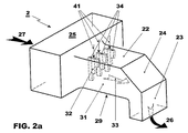
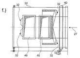
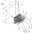
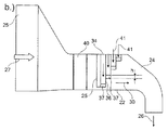
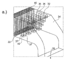
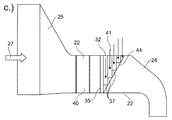
2 取入口部分、取入口ハウジング
3 燃料供給部
4 第1の燃焼器
5 高圧タービン
6 第2の燃焼器
7 低圧タービン
8 排熱回収ボイラ
9 高圧蒸気タービン
10 中圧蒸気タービン
11 低圧蒸気タービン
12 復水器
13 ポンプ
14 スタックへ
15 ブロワ
16 質量流量測定装置
17 ダイバータ/ダンパ
18 煙道ガス再循環(FGR)システム
19 炭素捕捉システム
19a 二酸化炭素吸着ユニット
20 混合器
21 大気空気
21a 直接接触冷却器
22 2の水平方向部分
23 2の垂直方向部分
24 2の曲げ部分
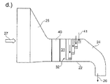
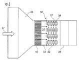
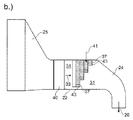
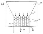
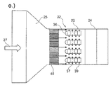
25 2の広幅吸入部分
26 圧縮器の取入口における空気流
27 大気空気
28 22の側壁
29 22の底部壁
30 22の頂部壁
31 22内の流路
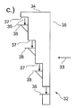
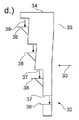
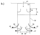
32 混合ダクト/混合指部
33 22内の空気流の方向
34 32の、煙道ガス再循環の取入口
35 32の前縁部
36 32の後縁部
37 32の排出口
38 衝突板
39 37における空気流および煙道ガス
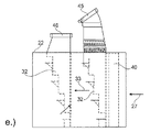
40 サイレンサ
41 34および32内部における煙道ガスの流れ
42 丸みを有する案内翼
43 真っ直ぐな案内翼
44 斜めの後縁部壁
45 上流列へ煙道ガスを導入するためのダクト
46 下流列へ煙道ガスを導入するためのダクト
h 排出開口37の高さ
Claims (14)
- ガスタービンユニット(1〜7)の圧縮器(1)のインレットより上流に設置される、煙道ガスの再循環を行う取入部(2)であって、
前記取入部(2)は、主要な空気流方向(33)に吸入空気の新鮮な空気流を流す流路(31)を有する少なくとも1つの領域(22)を含み、
前記流路(31)は、複数の側壁(28〜30)によって画定されており、
前記取入部(2)はさらに、少なくとも1つの前記側壁(28〜30)から前記流路(31)内に延在する少なくとも1つの混合ダクト(32)を有し、
前記混合ダクト(32)は、前記少なくとも1つの側壁(28〜30)に、再循環された煙道ガス(41)を取り込むための取入口(34)を有し、
前記取入部(2)はさらに、前記側壁(28〜30)から離隔されて設置された、再循環された煙道ガス(41)を前記混合ダクト(32)内部から前記空気流中へ吹き出すための少なくとも1つの排出開口(37)を有し、
少なくとも3つの前記混合ダクト(32)が列を成すように、相互に隣接して配置されており、
前記列の向きは実質的に、前記空気流方向(33)に沿うように配置されており、
最上流の前記混合ダクト(32)が前記列の前縁部を成し、
前記混合ダクト(32)が前記流路(31)内に延在する長さはすべて異なっており、
前記最上流の混合ダクト(32)が前記流路(31)内に最も大きく延在し、最下流の前記混合ダクト(32)が前記流路(31)内に最も小さく延在し、中間の前記混合ダクト(32)の長さは、下流における各混合ダクトの位置に応じて順次短くなっていく
ことを特徴とする取入部(2)。 - 前記混合ダクト(32)は、1つの前記側壁(22)にのみ取り付けられており、かつ、前記流路(31)内に自由に延在し、
前記混合ダクト(32)の先端領域に少なくとも1つの排出開口(37)が配置されている、
請求項1記載の取入部(2)。 - 前記流路内において、少なくとも3つの前記列が、前記空気流方向(33)に対して垂直な方向に沿って相互に離隔されて配置されており、
および/または、
前記流路内において、少なくとも3つの前記列が、前記空気流方向(33)に沿って相互に離隔されて配置されている、
請求項1記載の取入部(2)。 - 前記少なくとも1つの混合ダクト(32)または前記混合ダクトの列は、軸を前記流路(31)内における前記空気流方向(33)に対して実質的に垂直にして、当該流路(31)内に延在する、
請求項1から3までのいずれか1項記載の取入部(2)。 - 前記混合ダクト(32)は、当該混合ダクトを画定する4つの側壁を有し、
前記排出開口(37)は、前記空気流方向(33)に対して実質的に垂直な方向に開いているか、または、前記空気流方向(33)に対して実質的に平行かつ逆の方向に開いた構成である、
請求項1から4までのいずれか1項記載の取入部(2)。 - 前記少なくとも1つの排出開口(37)は、前記空気流方向(33)に対して実質的に垂直でありかつ前記混合ダクト(32)の軸に対して実質的に垂直な方向に開いた構成である、
請求項1から5までのいずれか1項記載の取入部(2)。 - 前記少なくとも1つの排出開口(37)内に、または、前記少なくとも1つの排出開口(37)の領域に、丸みを有するかまたは真っ直ぐな少なくとも1つの案内翼(42,43)が配置されている、
請求項6記載の取入部(2)。 - 前記少なくとも1つの排出開口(37)は、前記空気流方向(33)に対して実質的に垂直でありかつ前記混合ダクト(32)の軸に対して実質的に平行な方向に開いた構成となっており、
前記煙道ガスが流れる方向で見て当該排出開口(37)の下流に混合エレメントが配置されている、
請求項1から5までのいずれか1項記載の取入部(2)。 - 対ごとに平行に配置された4つの側壁(28〜30)によって前記流路(31)が画定されている領域(22)に、前記混合ダクト(32)が配置されており、
前記混合ダクト(32)または前記混合ダクトの列(32)の上流および/または下流において、サイレンサおよび/またはフィルタが前記領域(22)に配置されているか、または、当該領域(22)の実質的にすぐ上流および/またはすぐ下流に配置されている、
請求項1から8までのいずれか1項記載の取入部(2)。 - 前記混合ダクト(32)は、または、複数の混合ダクト(32)を有する列が設けられている場合には最上流に配置された混合ダクト(32)は、丸みを有する前縁部を有する、
請求項1から9までのいずれか1項記載の取入部(2)。 - 少なくとも3つの前記混合ダクト(32)が列を成すように相互に隣接して配置されており、
前記列の向きは、前記空気流方向(33)に実質的に沿うように配置されており、
最上流の前記混合ダクト(32)が、前記列の前縁部を成し、
前記混合ダクト(32)が前記流路(31)内に延在する長さはすべて異なっており、前記最上流の混合ダクト(32)が最も大きく前記流路(31)内に延在し、最下流の前記混合ダクト(32)は前記流路(31)内に最も小さく延在し、中間の前記混合ダクト(32)の長さは、下流における各混合ダクト(32)の配置位置に応じて順次かつ規則的に短くなっていき、
前記列の後縁部は、斜めになった後縁壁(44)によって形成されており、
前記列の各側壁において、前記空気流方向(33)に対して実質的に垂直でありかつ前記混合ダクト(32)の軸に対して実質的に垂直な方向に、3角形の排出開口(37)が開いた構成となっている、
請求項1から10までのいずれか1項記載の取入部(2)。 - 煙道ガス再循環を行う、ガスタービンであって、
前記ガスタービンは、請求項1から11までのいずれか1項記載の取入部を有することを特徴とするガスタービン。 - ガスタービンユニットの取入口に煙道ガスを再循環させる方法であって、
請求項1から11までのいずれか1項記載の取入部を用いて、再循環された煙道ガスと新鮮な大気空気とを混合する
ことを特徴とする方法。 - 再循環路における質量流量測定結果に基づいて、および/または、圧縮器上流の混合された取入空気の組成の測定結果に基づいて、および/または、燃焼品質の測定結果に基づいて制御される流れ制御エレメントが、前記混合ダクト(32)に、または当該混合ダクトより上流に設置されており、
前記流れ制御エレメントを使用して、再循環される煙道ガスの質量流量を制御する、
請求項13記載の方法。
Applications Claiming Priority (3)
| Application Number | Priority Date | Filing Date | Title |
|---|---|---|---|
| CH1152011 | 2011-01-24 | ||
| CH00115/11 | 2011-01-24 | ||
| PCT/EP2012/050964 WO2012101087A1 (en) | 2011-01-24 | 2012-01-23 | Mixing element for gas turbine units with flue gas recirculation |
Publications (2)
| Publication Number | Publication Date |
|---|---|
| JP2014505203A JP2014505203A (ja) | 2014-02-27 |
| JP5788024B2 true JP5788024B2 (ja) | 2015-09-30 |
Family
ID=43936485
Family Applications (1)
| Application Number | Title | Priority Date | Filing Date |
|---|---|---|---|
| JP2013550847A Expired - Fee Related JP5788024B2 (ja) | 2011-01-24 | 2012-01-23 | 煙道ガス再循環を行うガスタービンユニット用の混合エレメント |
Country Status (8)
| Country | Link |
|---|---|
| US (1) | US9453460B2 (ja) |
| EP (1) | EP2668387B1 (ja) |
| JP (1) | JP5788024B2 (ja) |
| KR (1) | KR101574981B1 (ja) |
| CN (1) | CN103328786B (ja) |
| CA (1) | CA2824710C (ja) |
| RU (1) | RU2573089C2 (ja) |
| WO (1) | WO2012101087A1 (ja) |
Families Citing this family (22)
| Publication number | Priority date | Publication date | Assignee | Title |
|---|---|---|---|---|
| EP2642097A1 (de) * | 2012-03-21 | 2013-09-25 | Alstom Technology Ltd | Verfahren zum Betrieb einer Gasturbine sowie Gasturbine zur Durchführung des Verfahrens |
| US20130269358A1 (en) * | 2012-04-12 | 2013-10-17 | General Electric Company | Methods, systems and apparatus relating to reheat combustion turbine engines with exhaust gas recirculation |
| EP2837795B1 (en) * | 2013-08-14 | 2019-05-01 | Ansaldo Energia IP UK Limited | Improved intake arrangement in gas turbine power plant |
| EP2837794A1 (en) * | 2013-08-14 | 2015-02-18 | Alstom Technology Ltd | Improved intake arrangement in gas turbine power plant |
| KR101485020B1 (ko) * | 2013-12-12 | 2015-01-29 | 연세대학교 산학협력단 | 초임계유체 냉각 가스터빈 장치 |
| WO2015147974A1 (en) * | 2014-03-26 | 2015-10-01 | Exxonmobil Upstream Research Company | System and method for the conditioning of recirculated exhaust gas |
| JP6522370B2 (ja) * | 2015-02-26 | 2019-05-29 | 三菱日立パワーシステムズ株式会社 | 放水ノズル及び混合槽 |
| RU2587511C1 (ru) * | 2015-03-10 | 2016-06-20 | Публичное акционерное общество Научно-производственное объединение "Искра" | Воздухоочистительное устройство |
| PL3344856T3 (pl) | 2015-09-01 | 2020-11-02 | 8 Rivers Capital, Llc | Systemy i sposoby wytwarzania energii przy zastosowaniu zintegrowanych cykli CO<sub>2</sub> |
| US10465714B2 (en) * | 2015-09-16 | 2019-11-05 | General Electric Company | Silencer duct having silencing element and couplers |
| US20170335734A1 (en) * | 2016-05-19 | 2017-11-23 | General Electric Company | Tempering Air System For Gas Turbine Selective Catalyst Reduction System |
| WO2019204394A2 (en) | 2018-04-17 | 2019-10-24 | Kayara Sammy | Wind-funneling for gas turbines |
| RU195474U1 (ru) * | 2019-11-12 | 2020-01-29 | Ооо "Термокон" | Подогреватель-каплеуловитель |
| CN111058947B (zh) * | 2020-01-09 | 2020-12-18 | 浙江特富发展股份有限公司 | 一种燃气轮机排气利用系统 |
| CN112007746A (zh) * | 2020-08-14 | 2020-12-01 | 苏州西热节能环保技术有限公司 | 一种磨煤机入口的方形一次风道均流装置 |
| RU2761711C1 (ru) * | 2021-04-16 | 2021-12-13 | Общество с ограниченной ответственностью Самара-Авиагаз | Воздухоочистительное устройство |
| CN114688736B (zh) * | 2022-03-21 | 2025-08-12 | 广东万和新电气股份有限公司 | 降噪装置及燃气热水器 |
| US11859544B1 (en) * | 2022-06-16 | 2024-01-02 | Solar Turbines Incorporated | Turbine exhaust gas recirculation mixer box |
| CN115976456B (zh) * | 2022-12-07 | 2024-09-27 | 镇江市博驰汽车配件有限公司 | 一种氛围循环的井式氮化炉及液压马达输出轴渗氮工艺 |
| IT202300003210A1 (it) | 2023-02-24 | 2024-08-24 | Nuovo Pignone Tecnologie Srl | Sistema e metodo per miscelare un flusso di gas di scarico di ricircolo con aria per ottenere una miscela di gas da alimentare ad una turbina a gas |
| KR102813394B1 (ko) * | 2023-09-18 | 2025-05-27 | 현대제철 주식회사 | 질소산화물 저감용 연소장치 |
| WO2025182185A1 (ja) * | 2024-02-26 | 2025-09-04 | 三菱重工業株式会社 | プラント及びプラント制御方法 |
Family Cites Families (23)
| Publication number | Priority date | Publication date | Assignee | Title |
|---|---|---|---|---|
| US4561245A (en) * | 1983-11-14 | 1985-12-31 | Atlantic Richfield Company | Turbine anti-icing system |
| SU1744290A1 (ru) * | 1990-07-09 | 1992-06-30 | Казанский Авиационный Институт Им.А.Н.Туполева | Способ работы газотурбинной установки |
| JP2548036Y2 (ja) * | 1991-01-25 | 1997-09-17 | アイシン精機株式会社 | 排気ガス還流装置 |
| DE19725668C1 (de) * | 1997-06-18 | 1998-10-29 | Daimler Benz Ag | Abgasrückführeinrichtung |
| US6027305A (en) * | 1997-08-13 | 2000-02-22 | Virginia Tech Intellectual Properties, Inc. | Method and apparatus for reducing high-cycle fatigue and suppressing noise in rotating machinery |
| JP3716133B2 (ja) * | 1999-07-07 | 2005-11-16 | 株式会社日立製作所 | 排気再循環型ガスタービン設備及びそのガスタービン設備を備えたコンバインドサイクル発電設備 |
| DE19933030A1 (de) * | 1999-07-15 | 2001-01-18 | Mann & Hummel Filter | Fluideinleitung für ein heißes Fluid in einer Hohlraumstruktur |
| US6293265B1 (en) * | 1999-10-04 | 2001-09-25 | Siemens Canada Limited | Exhaust gas recirculation system |
| WO2004101975A1 (de) * | 2003-05-15 | 2004-11-25 | Alstom Technology Ltd | Vorrichtung zur schalldämpfung in einem strömungskanal |
| DE102004012080A1 (de) * | 2004-03-12 | 2005-10-13 | Alstom Technology Ltd | Vorrichtung und Verfahren zum Erwärmen eines Gasstroms |
| US7140357B2 (en) * | 2004-09-21 | 2006-11-28 | International Engine Intellectual Property Company, Llc | Vortex mixing system for exhaust gas recirculation (EGR) |
| US7028680B2 (en) * | 2004-09-21 | 2006-04-18 | International Engine Intellectual Property Company, Llc | Two stage mixing system for exhaust gas recirculation (EGR) |
| JP4989062B2 (ja) * | 2005-04-28 | 2012-08-01 | バブコック日立株式会社 | 流体混合装置 |
| DE102005020484A1 (de) * | 2005-04-29 | 2006-11-02 | Mahle International Gmbh | Abgasrückführeinrichtung |
| US8029234B2 (en) * | 2007-07-24 | 2011-10-04 | United Technologies Corp. | Systems and methods involving aerodynamic struts |
| US7770564B2 (en) * | 2007-10-31 | 2010-08-10 | Cummins, Inc. | Diffuser plate for improved mixing of EGR gas |
| US7730878B2 (en) * | 2007-12-26 | 2010-06-08 | Toyota Motor Engineering & Manufacturing North America, Inc. | Exhaust gas recirculation devices |
| US8448418B2 (en) * | 2008-03-11 | 2013-05-28 | General Electric Company | Method for controlling a flowrate of a recirculated exhaust gas |
| EP2246532A1 (en) * | 2008-12-24 | 2010-11-03 | Alstom Technology Ltd | Power plant with CO2 capture |
| EP2248999A1 (en) | 2008-12-24 | 2010-11-10 | Alstom Technology Ltd | Power plant with CO2 capture |
| CH701235A1 (de) * | 2009-06-09 | 2010-12-15 | Alstom Technology Ltd | Vorrichtung zur Vermischung von frischer Ansaugluft mit rezirkulierter Abgasluft in einer Gasturbine. |
| CH701236A1 (de) * | 2009-06-09 | 2010-12-15 | Alstom Technology Ltd | Vorrichtung zur Schalldämpfung in einem Strömungskanal einer Gasturbine, welche Vorrichtung Zuführungselemente für rezirkulierte Abgase in den Ansaugluftstrom aufweist. |
| US8317390B2 (en) * | 2010-02-03 | 2012-11-27 | Babcock & Wilcox Power Generation Group, Inc. | Stepped down gas mixing device |
-
2012
- 2012-01-23 RU RU2013139317/06A patent/RU2573089C2/ru active
- 2012-01-23 CN CN201280006288.2A patent/CN103328786B/zh active Active
- 2012-01-23 JP JP2013550847A patent/JP5788024B2/ja not_active Expired - Fee Related
- 2012-01-23 CA CA2824710A patent/CA2824710C/en not_active Expired - Fee Related
- 2012-01-23 WO PCT/EP2012/050964 patent/WO2012101087A1/en not_active Ceased
- 2012-01-23 EP EP12700512.2A patent/EP2668387B1/en active Active
- 2012-01-23 KR KR1020137019111A patent/KR101574981B1/ko not_active Expired - Fee Related
-
2013
- 2013-07-23 US US13/948,296 patent/US9453460B2/en active Active
Also Published As
| Publication number | Publication date |
|---|---|
| RU2573089C2 (ru) | 2016-01-20 |
| CA2824710C (en) | 2016-09-06 |
| US9453460B2 (en) | 2016-09-27 |
| EP2668387B1 (en) | 2019-03-27 |
| US20130305732A1 (en) | 2013-11-21 |
| KR101574981B1 (ko) | 2015-12-07 |
| CA2824710A1 (en) | 2012-08-02 |
| CN103328786B (zh) | 2016-12-14 |
| CN103328786A (zh) | 2013-09-25 |
| JP2014505203A (ja) | 2014-02-27 |
| EP2668387A1 (en) | 2013-12-04 |
| RU2013139317A (ru) | 2015-03-10 |
| KR20130140120A (ko) | 2013-12-23 |
| WO2012101087A1 (en) | 2012-08-02 |
Similar Documents
| Publication | Publication Date | Title |
|---|---|---|
| JP5788024B2 (ja) | 煙道ガス再循環を行うガスタービンユニット用の混合エレメント | |
| US7861511B2 (en) | System for recirculating the exhaust of a turbomachine | |
| CN101725440B (zh) | 用于egr系统的进口系统 | |
| JP6073458B2 (ja) | 不均質な入力ガスを有するガスタービン発電プラント | |
| CN104428516B (zh) | 具有烟道气再循环的燃气涡轮功率装置及其运行方法 | |
| CN1245878A (zh) | 锅炉 | |
| KR20160063272A (ko) | 가스 터빈의 버너 | |
| CN101915429B (zh) | 烟气再循环系统中的燃烧器助燃风与循环烟气预混合装置 | |
| CN105992913A (zh) | 流内燃烧器模块 | |
| US6929470B1 (en) | Low NOx duct burner | |
| US11761407B1 (en) | Inlet mixer for exhaust gas recirculation in power generation systems | |
| US20110146282A1 (en) | System and method for reducing sulfur compounds within fuel stream for turbomachine | |
| JP2001355832A (ja) | エアポート構造 | |
| US20070125282A1 (en) | METHODS AND SYSTEMS FOR REDUCED NOx COMBUSTION OF COAL WITH INJECTION OF HEATED NITROGEN-CONTAINING GAS | |
| KR20250150120A (ko) | 재순환된 배기 가스 스트림을 공기와 혼합하여 가스 터빈으로 공급될 가스 혼합물을 얻기 위한 시스템 및 방법 | |
| US20240019125A1 (en) | Method and device for recursive sequential combustion | |
| CN1099559C (zh) | 多级远红外线放射机 |
Legal Events
| Date | Code | Title | Description |
|---|---|---|---|
| A621 | Written request for application examination |
Free format text: JAPANESE INTERMEDIATE CODE: A621 Effective date: 20131225 |
|
| A131 | Notification of reasons for refusal |
Free format text: JAPANESE INTERMEDIATE CODE: A131 Effective date: 20141006 |
|
| A601 | Written request for extension of time |
Free format text: JAPANESE INTERMEDIATE CODE: A601 Effective date: 20150106 |
|
| A601 | Written request for extension of time |
Free format text: JAPANESE INTERMEDIATE CODE: A601 Effective date: 20150206 |
|
| A521 | Request for written amendment filed |
Free format text: JAPANESE INTERMEDIATE CODE: A523 Effective date: 20150302 |
|
| TRDD | Decision of grant or rejection written | ||
| A01 | Written decision to grant a patent or to grant a registration (utility model) |
Free format text: JAPANESE INTERMEDIATE CODE: A01 Effective date: 20150629 |
|
| A61 | First payment of annual fees (during grant procedure) |
Free format text: JAPANESE INTERMEDIATE CODE: A61 Effective date: 20150728 |
|
| R150 | Certificate of patent or registration of utility model |
Ref document number: 5788024 Country of ref document: JP Free format text: JAPANESE INTERMEDIATE CODE: R150 |
|
| S533 | Written request for registration of change of name |
Free format text: JAPANESE INTERMEDIATE CODE: R313533 |
|
| R350 | Written notification of registration of transfer |
Free format text: JAPANESE INTERMEDIATE CODE: R350 |
|
| S111 | Request for change of ownership or part of ownership |
Free format text: JAPANESE INTERMEDIATE CODE: R313113 |
|
| R350 | Written notification of registration of transfer |
Free format text: JAPANESE INTERMEDIATE CODE: R350 |
|
| LAPS | Cancellation because of no payment of annual fees |