EP2669100B1 - Agencement de support pour un attelage avec un élément de support durci par presse - Google Patents
Agencement de support pour un attelage avec un élément de support durci par presse Download PDFInfo
- Publication number
- EP2669100B1 EP2669100B1 EP13002739.4A EP13002739A EP2669100B1 EP 2669100 B1 EP2669100 B1 EP 2669100B1 EP 13002739 A EP13002739 A EP 13002739A EP 2669100 B1 EP2669100 B1 EP 2669100B1
- Authority
- EP
- European Patent Office
- Prior art keywords
- base body
- cross
- support assembly
- reinforcing
- assembly according
- Prior art date
- Legal status (The legal status is an assumption and is not a legal conclusion. Google has not performed a legal analysis and makes no representation as to the accuracy of the status listed.)
- Active
Links
Images



Classifications
-
- B—PERFORMING OPERATIONS; TRANSPORTING
- B60—VEHICLES IN GENERAL
- B60D—VEHICLE CONNECTIONS
- B60D1/00—Traction couplings; Hitches; Draw-gear; Towing devices
- B60D1/48—Traction couplings; Hitches; Draw-gear; Towing devices characterised by the mounting
- B60D1/485—Traction couplings; Hitches; Draw-gear; Towing devices characterised by the mounting mounted by means of transversal members attached to the frame of a vehicle
Definitions
- the invention relates to a carrier arrangement for a trailer coupling or a load carrier, according to the preamble of claim 1.
- Such a carrier arrangement is sufficient DE 10 2010 012 825 A1 out.
- Carrier assemblies are usually hidden under a rear bumper of the vehicle, such as a passenger car, in particular with an internal combustion engine, mounted and carry the hitch or a holder and / or optionally also supports for a load carrier, which can be arranged on the carrier assembly.
- the carrier arrangement has at least one carrying component which has a base body which is made entirely or at least in sections by press-hardening.
- the main body is thermoformed during press-hardening and then cooled, in particular quenched.
- the main body is e.g. heated before forming and / or processed in a heated press tool. Conveniently, the cooling of the body takes place in the pressing tool.
- the total or partially press-hardened base body can thus have a rigidity which is best adapted to the respective requirement.
- Local hardness differences in the component can ensure a homogeneous force and stress curve in the support component, in particular the cross member.
- Local recesses on the base body advantageously serve to reduce the mass. Local formations may conveniently improve stiffness.
- the plurality of basic body such as shells or shell elements can be connected to each other, for example, be joined. It can be produced a rigid shell contour. It is also possible that a front and a rear shell or a shell element and / or an upper and a lower shell or shell element are assembled. In itself, any shell elements be provided, which are then connected to each other.
- the shell elements can be configured in a wide variety of configurations and then connected together. For example, a rear and / or a front switching element can be added to an upper and a lower switching element. Even diagonal joints between shells or shell elements are readily possible.
- a carrier structure adapted to the force and voltage curve is possible. Less material is needed so that the carrier assembly is lightweight and inexpensive, e.g. also saves fuel.
- the main body is high-strength, thin-walled and lightweight.
- the invention enables a targeted homogeneous introduction of forces and moments in the body.
- a cross member is suitably hardened in the middle higher strength and has outward course with lower hardness, advantageously analogous to the force and voltage curve when using or loading the cross member. This is e.g. adjustable by partial cooling in the tool.
- the base body is produced by a direct press hardening and / or indirect press hardening and / or partial press hardening.
- the main body may first be cold formed and subsequently post-processed by press hardening.
- some areas of the body remain without further treatment, while other areas are post-treated by press hardening and thus have a higher strength and thus a higher rigidity and load capacity.
- the high strength of the support member is achieved by heating boron steel to 880-950 ° C, then hot forming and cooling in the die so that it is hardened.
- uncured boron steel has about 600 N / mm 2 Rm and 20% A
- hardened boron steel eg 22MnB5, BTR 1650, Usibor 1500
- Hardening directly in the tool minimizes or prevents distortion of the main body or of the supporting component.
- the main body comprises, for example, a manganese steel, a manganese-boron steel or the like. Preferred is 22MnB5 steel.
- the main body is preformed, for example, from a sheet metal blank, for example, formed and then reworked by press hardening.
- the base body can also be produced by a casting process and then cured or stiffened by press hardening in whole or in sections.
- a heating time for austenitizing the main body is, for example, 5-10 minutes or so.
- the austenitizing temperature is preferably in a range of 880 ° C to 950 ° C.
- a cooling time in a rigid region of the main body is approximately between 1 s and 10 s, for example 3-5 s. Thus, therefore, a particularly rigid region of the body is achieved.
- a softer area of the carrying component or of the base body, for example in the region of the longitudinal ends of the cross member or in the region of the side supports, can cool much longer, for Example several minutes. Thus, it can be achieved by targeted cooling that the main body or the support member has different stiff areas.
- the main body has, for example, a metal wall which is between 1 mm and 3 mm thick, preferably between 1.5 and 2.5 mm.
- the base body in particular when it forms the cross member, has a tensile strength of about 400-800 N / mm 2 , for example, at its longitudinal end regions over its cross section.
- the cross member at the longitudinal end regions is relatively soft or gives way to train.
- the cross member is advantageously substantially zugfester, for example larger than 1200 N / mm 2 , in particular greater than 1500 N / mm 2 .
- the main body may preferably be provided with a scale-inhibiting coating. This improves, among other things, the post-processing, for example by welding or the like.
- the main body expediently has a coating based on aluminum-silicon.
- a galvanizing of the body is advantageous. Both contribute to avoid or at least reduce oxidation of the steel sheet when heated, for example, to more than 800 ° C, which may occur in the press-hardening.
- the use of an AlSi-based coating prevents scaling and thus specifically reduces tool wear during forming. In addition, it forms the basis for a corresponding corrosion protection, just like a typical galvanizing of sheet metal.
- the base body has at least one reinforcement deformation, in particular a reinforcement bead or reinforcing rib.
- the reinforcing deformation in particular a reinforcing bead, is introduced into the base body during the press hardening.
- it can also be introduced even during a cold forming and, for example, further deepened during the press hardening and / or after-treatment with heat.
- the base body of the support member is opposite to a second, in particular produced by press-hardening or without press-hardening, supporting body.
- the carrier arrangement has at least one carrying component designed as a multi-component component, which comprises a main body and a reinforcing body connected to the main body comprising a rib structure and / or a foam body of a technical foam.
- the foam body consists for example of an open-pored and / or a closed technical foam. It is also possible that the rib structure is reinforced with a technical foam.
- a so-called hybrid component which comprises two or more components, namely, on the one hand, a base body and a reinforcing body connected to the main body.
- the multi-component component may also comprise further reinforcing bodies and / or base bodies.
- the reinforcing body comprises a rib structure, for example a kind of truss structure or a technical foam or both.
- the reinforcing body fulfills its reinforcing function, while the base body provides, so to speak, the basic structure of the supporting component.
- the main body is formed for example as a receiving body, in which the reinforcing body is received.
- the main body has a receiving recess, in which the reinforcing body is introduced.
- the recess is for example U-shaped in cross section.
- the basic body may for example also be designed in the manner of a shell.
- the shell consists e.g. made of steel, light metal, plastic. Of course, mixed forms of the aforementioned embodiments are possible.
- the main body is formed for example by cold forming or hot working or both. It can e.g. a hot forming with controlled quenching in the tool, so a press hardening, be provided.
- the main body may for example consist of steel, light metal or plastic.
- the main body itself can already be thin-walled, light and high-strength.
- the at least one on the Body arranged reinforcing body increases the rigidity of the support member.
- a thin-walled metal construction of the base body can be reinforced by a stiffening of plastic so that they can easily absorb the forces caused by the hitch or the load carrier, impact forces in an accident or the like.
- the main body can have recesses for weight reduction.
- further potentials for mass reduction by means of local recesses can advantageously be utilized.
- the reinforcing body expediently has at least one contact wall section for surface contact, in particular planar connection, with a main body wall section of the main body.
- the reinforcing body and the body can lie flat against each other.
- the rib structure of the reinforcing body extends away from the contact wall portion.
- the main body expediently comprises at least two mutually angled or mutually opposite main body wall sections, against which contact wall sections of the reinforcing body lie flat.
- the base body may be L-shaped in cross-section, U-shaped or the like.
- the reinforcing body has at least where it comes into contact with the body, expediently the same Cross-sectional contour, so that the two parts can lie flat against each other.
- the main body and the reinforcing body are advantageously made of different materials.
- the base body consists of a metallic material
- the reinforcing body consists of a plastic material
- the main body and the reinforcing body made of plastic or light metal, but of different quality.
- the base body made of steel, while the reinforcing body is made of light metal.
- the main body may also be e.g. consist of a fiber-reinforced plastic or unreinforced plastic.
- the reinforcing body consists of a plastic, preferably of a fiber-reinforced plastic.
- the reinforcing body may be itself formed as a hybrid body or multi-component body, i. for example, consists of different materials.
- the reinforcing body is expediently provided integrally with at least one fastening element, for example a hook, a snap hook, a screw receptacle, a cable clamp or the like.
- the fastener is integral with the reinforcing body.
- the reinforcing body can also be a holding receptacle for a component, for example a cable, have to be attached to the support assembly.
- the additional component for example, the cable can be accommodated protected in the reinforcing body. If the reinforcing body is thus cast, for example in an injection molding, there is the possibility of integrating any additional functions such as fasteners, bearings, screw, cable clamps, etc. in a single operation. This makes it possible to save time-consuming and costly reworking and assembly processes.
- the main body is expediently designed as a formed part or has a formed part.
- the reinforcing body is preferably designed as an extruded component, an extrusion component or cast component.
- the reinforcing body is expediently produced by injection molding or pressure casting and / or related primary molding processes.
- the reinforcing body in particular the rib structure or side walls of the reinforcing body, different wall thicknesses, also on one and the same wall of a rib or side wall, are possible.
- the specifically defined wall thicknesses of the reinforcement by the reinforcing body allow an adaptation of the stiffness curve to the force and stress curve in the support component, in particular in the cross member. A targeted homogeneous introduction of forces and moments in the body is possible.
- the main body of the support member is expediently reinforced with a first and a second reinforcing body, wherein the reinforcing body may have the same or a different rigidity.
- the reinforcing body may have the same or a different rigidity.
- several reinforcing body of the same type or different design can be prepared and mounted on the main body.
- different stiff sections of the support member can be produced without special measures are necessary on the body, of course, the main body over its longitudinal direction or in other directions may have different stiffness, eg by appropriate use of materials, suitable geometries, press-hardened sections or the like ,
- the rib structure expediently has ribs or is formed by ribs, the narrow sides of which are oriented to side walls of the reinforcing body or the base body, so that the side walls are supported on the narrow sides of the ribs.
- the ribs of the rib structure extend substantially horizontally in the vehicle-mounted state of the carrier arrangement.
- the reinforcing body is received positively in the base body.
- a connection between the reinforcing body and the main body is possible over a large contact area.
- the base body is encapsulated with the reinforcing body or the reinforcing body is molded onto the base body. It is also possible that the reinforcing body is introduced into an inner space of the main body by spraying or casting. For example, the main body is laterally open, so that from there the reinforcing body can be introduced by an injection process. With the injection molding of rib-shaped reinforcements and stiffeners made of plastic, a thin-walled structure of, for example, metallic or made of fiber-reinforced plastic particular body be stabilized very effectively with little additional weight.
- the main body and the reinforcing body can also be produced as two separate components and then joined together to form the at least one supporting component.
- the reinforcing body and the base body are, for example, welded together, glued to each other or the like. Furthermore, the reinforcing body can be riveted to the base body, for example. Furthermore, it is possible for the reinforcing body to be connected, for example, to the base body in a thermoplastic manner. For example, from the reinforcing body protrusions, which are fused with the body. Of course, other merger points are readily feasible.
- latching projections, hook projections or the like on the base body and / or reinforcing body in order to hook or lock the two components together.
- the two components can also be connected to each other by further methods, for example by gluing and / or by clinching and / or by punch riveting and / or by folding or any combination thereof.
- a clinched or stamped rivet connection can additionally be adhesively bonded
- a rebate connection can additionally be improved by a lock or the like.
- an interior of the base body, in which the reinforcing body is arranged is closed by a cover.
- This cover may for example be formed by a foil or a wall, so that the arranged in the interior reinforcing body, for example, the rib structure, not dirty.
- the cover can also be formed by a further, in particular complementary, main body or support body, which is firmly connected to the other base body, for example, welded, glued or the like. This creates a particularly sustainable construction.
- the support assembly comprises at least one support member having a base body having a support wall and an integral to the support wall by a prototype Method, in particular by a casting method, and / or a forming method, eg by extruding and / or by forging, integrally formed rib structure, wherein the support member forms a part of the cross member and extends to the transverse center of the cross member.
- Such a base body with a support wall and integral with the support wall rib structure is particularly resilient. There is an integral connection between the ribs and the supporting wall so that it is particularly well reinforced.
- the support member may be optimally adapted in contour to the contour of the vehicle, for example, have a suitable curvature or the like.
- integrally fasteners may be formed for attachment to the vehicle.
- the main body or the supporting component is produced, for example, by die-casting, die-casting, low-pressure casting, by compression molding or the like. An injection molding process is readily possible.
- the support member can also be produced in the context of an extrusion process.
- the base body comprises aluminum, magnesium or their alloys.
- the base body is produced by compression molding.
- This method which is also referred to as squeeze casting, produces no or hardly voids, turbulences and similar structural impairments.
- the rib structure expediently comprises ribs running obliquely to the supporting wall, for example plate-like or wall-like.
- the ribs may also be formed by webs, so that they have a kind of rod shape.
- the ribs are preferably connected to each other.
- the rib structure is preferably designed in the manner of a truss.
- the ribs of the rib structure advantageously extend vertically in the vehicle-mounted state of the carrier assembly.
- ribs run quasi from top to bottom.
- the main body expediently has at least one second wall opposite the supporting wall or angular to the supporting wall.
- the rib structure is integrally formed on the at least one second wall in the primary molding process or by forging. This creates an overall highly resilient structure.
- the supporting wall expediently forms part of a supporting wall arrangement which encloses an interior in which the rib structure is arranged.
- the walls are arranged, for example, in a U-shape.
- the cross member expediently has at least two supporting components, which are connected to one another at their longitudinal ends.
- the at least one holder is expediently arranged between the two supporting components.
- the holder is used for example for connecting the two support components.
- the holder is advantageously a structural component for reinforcing the cross member.
- a support member according to the invention can also provide the support in whole or in part.
- the holder may be formed as a bearing housing for a movable trailer coupling, a plug-in receptacle for a coupling arm or in a support member.
- two, eg in the longitudinal direction, next to each other arranged support members may form the holder or a receptacle for the holder.
- the holder may for example be a casting or a rotating part, in particular of a wrought alloy.
- the holder can be cast for example with the support member according to the invention, be soldered to this or the like. Also adhesive techniques are readily possible.
- a mounting flange is present on the support member.
- two supporting components can be welded, soldered, glued or screwed together. Furthermore, it is possible to perform a so-called composite casting to connect 2 supporting components together.
- the at least one side part is advantageously designed as a crash profile for deformation in an impact or has such a crash profile.
- the cross member can be produced exclusively by one or more support components which are produced by press hardening or in whose production process the press hardening represents a process step.
- the cross member for example, by one or more support members, consisting of a Main body with one or more reinforcing bodies exist.
- at least one support component may be provided with a base body having a base body on which a rib structure is integrally formed on a support wall, for example by a primary molding method, for example a casting method, or a forming method, eg forging or extrusion, or the like.
- a press-hardened base body is also provided with a reinforcing body and / or, for example, that a base body, which is produced by a casting process, additionally subjected to a press-hardening step, so that it at least partially a greater rigidity and hardness than before this processing step.
- the measures according to the invention enable an optimal adaptation of the properties of the cross member to its respective load.
- the cross member advantageously has in the region of the at least one holder and / or transversely or in a transverse center region a higher rigidity and / or a larger cross section and / or a higher resistance moment than at its longitudinal ends.
- the cross member has an approximately constant tension along its longitudinal axis between its longitudinal ends when a force acts on it.
- the cross member is thus over its longitudinal extent, at least over that longitudinal extent which extends between the side members, a substantially uniformly loadable component.
- the cross member is so mechanically ideal loadable with a favorable use of materials, small dimensions and lightweight construction.
- the cross member expediently has a supporting wall and a wall opposite the supporting wall. A distance between the support wall and the opposite wall is greater in the region of a transverse center of the cross member than in the region of the longitudinal ends of the cross member.
- a rib structure of the cross member advantageously has a higher rigidity in the region of the transverse center than in the region of the longitudinal ends of the cross member.
- the rib structure may be integrally formed with a constituent part of a reinforcing body and / or with a wall of a main body of the crossbeam.
- the ribs in the region of the transverse center are denser and / or have a larger cross-section and / or a different geometry and / or spatial arrangement to each other than in the region of the longitudinal ends of the cross member.
- the at least one support component expediently forms part of the cross member and / or at least one side support and / or the holder.
- the support member according to the invention can be used to various components of the carrier assembly with advantage. It is particularly preferred if the support component forms part of the cross member or the cross member as a whole.
- the support member may also be multi-part or a component of the support assembly, such as the cross member or a side support, may be formed by a plurality of support members, which are interconnected:
- a first and a second part of the supporting component for example two parts of the basic body and / or the basic body and the reinforcing body, or two supporting components are advantageously by a welded connection and / or a screw connection and / or a rivet connection and / or by mechanical joining and / or thermal joining and / or by hybrid joining with an adhesive.
- the carrier arrangement expediently comprises the trailer coupling.
- a coupling body carrier on which a coupling body, for example a coupling ball, is arranged, detachably connectable to the carrier assembly, for example, to the holder or arranged on the holder plug-in receptacle attached.
- the dome body carrier can therefore be removable, in particular pluggable, or be firmly mounted on the motor vehicle.
- the coupling body carrier for example, a coupling arm can also be mounted on a bearing such that the coupling body carrier is mounted adjustably between a position of use and a non-use position.
- the dome body carrier or the dome body In the non-use position of the dome body carrier or the dome body, for example, under a rear skirt or a Hidden rear bumper of the motor vehicle, in any case substantially covered over view, so that a visually appealing design is made.
- the dome body In the operating position, however, the dome body protrudes in front of the vehicle, for example, in front of a bumper, so that the trailer can be attached.
- the bearing is for example a pivot bearing, a sliding bearing or a combination thereof, for example a swivel-slide bearing.
- the bearing may form part of the holder of the carrier assembly or be attachable to the holder.
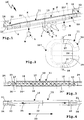
- carrier assemblies 10, 110, 210, 310 are shown, to which, for example, a trailer coupling 1 with a ball neck 2 and a ball head 3 or other coupling element can be arranged or arranged, or for example, a load carrier L can be arranged.
- the carrier assemblies 10, 110, 210, 310 have partially identical or similar components, which are provided with the same reference numerals, partially with reference numerals, which differ from each other by 100.
- the carrier assemblies 10, 110, 210, 310 have cross members 11, 111, 211, 311 from which side supports 12, 112, 212, 312 extend, which are intended to be mounted on a vehicle F.
- the carrier assemblies in particular the cross member 11, 111, 211, 311, hidden behind a bumper S of the vehicle F, which is shown partially schematically.
- the side supports 12, 112, 212, 312 attached to side members T or to a rear wall H of a body K of the vehicle F, for example screwed.
- a holder 15, 215, 315 is provided for fastening the trailer coupling 1.
- the holder 15, 215, 315 comprises, for example, a plug-in receptacle into which a plug projection of a ball bar can be inserted.
- the holder 15, 215, 315 may also be provided as a support for a pivot bearing, sliding bearing or the like, so that the hitch 1 between the solid-line service position G shown for drawing a trailer and a non-use position N, shown in dashed lines is adjustably mounted on the support assembly 10-310.
- a hitch can also be firmly attached to the cross member 11-311.
- the support concept according to the invention is also suitable for load carriers which have, for example, coupling parts M which can be fastened to, for example, plug-in receptacles attached to holders 15 'designed, for example, as plug receptacles or other coupling parts.
- the support concept is highly resilient, so that a heavier load carrier can be worn, which will become clear below.
- the side members 12 and 112 are identical and comprise, for example, a support arm 13 which is connected on the one hand to the cross member 11 or 111 and on its other, free side a support plate 14 for attachment to the body K of the vehicle F has. On the support plate 14, for example holes are provided for the insertion of screws. That does not matter.
- the cross member 11 comprises a base body 16, which is designed as a receiving body for reinforcing body 17, 18, 19.
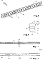
- the reinforcing body 17 is in the Figures 5-8 shown in detail.
- the reinforcing body 17 is arranged, for example, in a transverse center region 20 of the cross member 11, while the reinforcing bodies 18 and 19 are arranged next to the reinforcing body 17 in the direction of the two longitudinal ends 21 of the cross member.
- the main body 16 and the reinforcing bodies 17-19 form a multi-component support member 50.
- the base body 16 is designed, for example, as a sheet-metal forming part and has a middle section 22 with an approximately constant cross-sectional contour.
- the profile of the base body tapers 16.
- lateral portions 23 follow, which have a conical shape.
- mounting sections 24 are welded to the side beams 12, glued, screwed or the like.
- the base body 16 is presently designed as a one-piece component, wherein, of course, a multi-part construction over a longitudinal extension 25 of the cross member 11 or transverse to this longitudinal extent 25 is readily possible.
- the base body 16 has in the sections 22 and 23 a cross-sectionally U-shaped configuration with a bottom wall, which forms a first support wall 26, and protrude from the side legs in the form of support walls 27. Between the support walls 26 and 27 of the base body 16 is rounded, so that a homogeneous, uniform structure is formed. From the support walls 27 are laterally flange leg 28 from.
- the base body 16 is configured as a forming part, wherein, of course, alternatively, a casting, forged part or the like would be possible.
- the base body 16 is made of metal, in particular steel, although other materials, for example plastics, in particular fiber-reinforced plastics, are readily possible.
- the reinforcing body 17-19 fit positively into an interior 29 of the cross member 11, so that they find optimal support there.
- the reinforcing bodies 17-19 are, for example, castings, extruded components, extruded components or the like.
- the example of the reinforcing body 17 is intended to explain this concept.
- the other reinforcing bodies 18 and 19 are basically similar.
- FIG. 3 is for better understanding, where the dividing lines between the individual reinforcing bodies 17,18 and 19 so to speak, dashed lines are shown.
- the modular concept makes it possible to produce the reinforcing bodies with relatively simple tools or inexpensive tools. Nevertheless, they fulfill their stabilization and amplification function on the cross member 11.
- the reinforcing body 17 has, for example, a bottom wall 31 which is suitable for the supporting wall 26, to which side leg walls 32 adjoin, of which flange legs 33 protrude laterally.
- the outer contour of the reinforcing body 17, so to speak, its fitting contour that fits the interior 29, corresponds to the inner contour of the interior 29.
- the flange legs 28 and 33 are preferably flat, which represents an optional measure.
- a rib structure 30 is arranged in an inner space of the reinforcing body 17, which is bounded by the bottom wall 31 and the two side walls 32.
- the rib structure 30 includes with its end faces to the bottom wall 31 adjacent, wall-like ribs 34.
- the ribs 34 extend diagonally between the two lateral walls 32nd
- the ribs 34 extend horizontally in the vehicle F mounted state of the support assembly 10, ie their free end faces and connected to the bottom wall 31 end faces extend vertically. Another orientation of the ribs or individual Ribs are possible depending on stiffness requirement easily.
- knot-like reinforcements 35 are provided, for example in the form of tubes or sleeves. This measure is optional. For example, in rib structures 30 'and 30 "of the reinforcing bodies 18 and 19, no reinforcements are provided.
- the ribs of the rib structures 30 'and 30 "are slightly weaker, ie less thick than the ribs 34, because in the transverse center region 20 a higher rigidity of the cross member 11 is more expedient than in the region of the longitudinal ends 21.
- care is taken in an optimal manner in that reinforcing bodies are used in the respective desired load capacity and rigidity.
- ribs may be used to advantage, for example honeycomb structures, zigzag structures or the like, similar to e.g. in the case of the rib structures illustrated in the carrier assemblies 210 and 310.
- the reinforcing body 17-19 are glued, for example, in the base body 16, welded thereto or the like. Also clinching or other other fastening techniques, such as rivets, are readily possible. Furthermore, it would also be possible to inject the reinforcing body 17 or 18 or 19 on the base body 16, for example, to inject it into the interior 29.
- a particularly good reinforcement can also be achieved, for example, if a second basic body 16 'is arranged on the main body 16, as in FIG. 2 indicated.
- This second one Base body 16 ' which can also be stiffened with a reinforcing body or a plurality of reinforcing bodies, conceals at the same time the so-called open side of the main body 16 into which the reinforcing bodies 17-19 are inserted and thus acts as a cover.
- the second base body 16 'and another cover for covering the rib structure 30-30' arrange, for example, a film, a plate or the like.
- the cross member 111 of the support assembly 110 is equipped with an alternative stiffening concept, in which even without reinforcing body optimum strength and an optimal voltage curve is possible.
- reinforcing body in the type of reinforcing body 17-19 possible.
- the cross member 111 has a main body 116 with a central portion 122, with a relatively large cross section, to which laterally to the longitudinal ends 21 in cross section tapered portions 123 and finally longitudinal outer mounting portions 124 connect, where the side support 112 are attached.
- the basic structure of the base body 116 is therefore similar to the basic structure of the cross member 11.
- the middle portion 122 extends over a longer range of the transverse width of the vehicle F than the central portion 22.
- the two tapered portions 123 are shorter in the longitudinal direction 25.
- the main body 116 forms the cross member 111 as a whole.
- the middle section 122 has a supporting wall 126 configured as a bottom wall, from which side legs extend sideways, namely supporting walls 127. Flange legs 128 adjoin the supporting walls 127.
- the cross-sectional contours of the base body 16 and 116 are therefore very similar, these cross-sectional contours are only to be understood as an example, ie that at a base body at any time other cross-sections, for example, L-shaped cross-sections or the like are possible.
- the cross member 11 forms a cross member quasi constant tension, which is achieved by the press-hardening described below.
- the base body 116 has a reinforcing deformation in the form of a reinforcing recess or reinforcement bead 137.
- the reinforcing bead 137 is widest in the region of the transverse center 36, while the longitudinal ends 21, ie with respect to the longitudinal extent 25, becomes narrower.
- the frontal view results in a diamond-shaped shape from behind, this being understood only as a convenient measure, i. that at any time other reinforcing recesses or reinforcing transformations are possible, namely deeper, less deep, reinforcing transformations, other geometries or the like. The person skilled in the art will select the best geometry and shape for the particular application.
- reinforcing beads 138 are provided between the sections 123 and the reinforcing bead 137. These are designed in principle as elongated U-shaped longitudinal grooves.
- the base body 116 forms a support member 150.
- the reinforcement bead 137 has, for example, a bottom wall 139 and side walls 140 extending between the bottom wall 139 and the support wall 126 of the base body 116.
- the transition areas between the support wall 126 and the side walls 140 are preferably rounded.
- the end portions of the reinforcing beads 137 and 138 are also advantageously rounded.
- the main body 116 is preferably in one piece and is preformed, for example, in the context of a cold-forming process, wherein the reinforcing beads 137 and 138 are not or not present in the extent shown in the blank produced thereby. In principle, however, it would be possible to produce the reinforcement beads 137 and 138 already in the cold forming in the range shown.
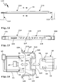
- the reinforcement bead 137 is produced by a hot forming tool 40 comprising an embossing punch 41 and an embossing punch 42 having embossing contours 43 and 44 on their front side to form the reinforcing bead 137.
- the embossing contours 43 is designed, for example, as a recess, while the embossing contour 44 forms a projection which, so to say, fits into the reinforcing bead 137.
- the forming tool 40 is heatable, expediently also coolable.
- a temperature control device 45 for controlling the temperature of a fluid e.g. Oil, water or the like, provided, which can flow into lines 46 to the embossing contour 43 and there, for example in the region of the curves between the support walls 126 and 127 causes heating of the embossing punch 41.
- the fluid can also serve as a cooling medium.
- embossing die 42 an eddy current heater 49 is exemplified, which is located in the region of the embossing contour 44 and there causes a local heating.
- the heat treatment preferably also takes place in the region of the reinforcement beads 138. There, however, a lower strength is expediently set. It can even be provided that 25 different heat-treated zones are created along the longitudinal extent, so that for example in the transverse center region 20, a high strength is achieved, which then decreases as continuously as possible in the direction of the longitudinal ends 21. There, so the cross member 111 is so to speak rather tough and yielding, while in the transverse center region 20 has a high strength and thus load capacity, for example by the trailer coupling 1 and / or in a rear impact or the like.
- the cross member 111 can also have a reinforcing body.
- a reinforcing body for example, one could incorporate a modified reinforcing body 117 in the transverse center region 20, which is in FIG. 8 is shown.
- the reinforcing body 117 has, for example, recesses 118 and 119 matching the reinforcing beads 137 and 138, so that its bottom wall 31 is positively attached to the inside of the base body 16 can be, so it rests substantially flat against the support wall 126.
- the carrier assembly 210 comprises a so-called two-part cross member 211, which is composed of support members 250.
- the support members 250 each include a side support 212.
- the side supports 212 include a plate-like support arm 213.
- the support arms 213 are bolted to, for example, side rails T of the vehicle F and the body K, respectively.
- the support arms 213 may be configured as crash components, i. they are yielding in a rear impact on the vehicle F and act impact-absorbing.
- the support arms 213 are laterally and angularly from cross member arms 251 from.
- the cross member arms 251 each form a sub-segment of the cross member 211st
- the cross member arms 251 each have a support wall 226 located closer to the rear wall H and a support wall 227 remote from the rear wall H.
- the support wall 226 has a substantially rectilinear course, in its contour thus matches the rear contour of the body K, the support wall 227 has a curved, arcuate course.
- the distance between the support wall 226 and the support wall 227 is greatest in the region of the transverse center 36 of the cross member 211, while in the region of the longitudinal ends 21, in the transition region to the side supports 212, the distance between the support walls 226 and 227 is smallest. There, the supporting walls 226 and 227 merge into one another, whereby, of course, a certain distance would still be possible there as well.
- a rib structure 230 extends between the support walls 226 and 227.
- the rib structure 230 includes ribs 234 that extend zigzag between the two support walls 226 and 227.
- the ribs 234 are plate-like.
- the ribs have a vertical orientation in the state of the carrier assembly 210 mounted on the vehicle F, i. their free narrow sides are up and down.
- the support walls 226 and 227 and the rib structure 230 are components of a base body 216.
- the carrier assembly 210 may also be covered by other components, such as a rear apron or panel B of the vehicle F
- the ribs 234 abut with their narrow sides in each case against the support walls 226 and 227 or are integrally connected therewith.
- the innovative manufacturing process in which the two support components 250 are each cast components or extruded profiles or extruded components in one piece, is used.
- the supporting components 250 are produced, for example, directly as aluminum extruded profiles. It is understood that the support members 250 also by a forming process, such as forging, can be produced.
- the two support members 250 are symmetrical, so that they can be produced with the same tools, in particular the same forms.
- the cross member arms 251 each have a receiving portion 253 for forming the holder 215.
- the two crossbar arms 251 with their end portions 252 abut each other frontally limit the receiving portions 253 each one half of the holder 215th
- integrally in the Cross member 211 may be introduced a holder for receiving a trailer hitch or the cross member 211 provide the holder for the hitch (or a load carrier).
- a further embodiment may provide that the receiving sections 253 serve, for example, as a receptacle for a separate mounting of the trailer coupling, for example a receiving tube, the trailer coupling.
- this receiving tube is received in the receptacle 254 defined by the receiving sections 253, for example soldered there, held in place by a press fit or the like.
- Such a receiving tube or other mounting component of a hitch could also be connected in other ways with the cross member arms 251, for example by a screw, welding, gluing or, which is also advantageous in the frame a Verbundgusses in the production of the support members 250 directly mitgest or formed.
- connecting webs 255 between the support walls 226 and 227 and / or the adjacent ribs 234.
- the connecting webs 255 are provided with a semi-cylindrical cross-section recess which provides the receptacle 254 in each case in half.
- a mounting flange 259 is advantageously provided in front of the lateral support walls 227.
- the mounting flanges 259 serve, for example, to connect the support components 250 to one another.
- the support members 250 are otherwise connected to each other, for example, by attached to the side walls 226 and / or 227 connecting plates or the like.
- the rib structure 230 could also have a different orientation if other rigidity requirements exist.
- it is advantageous that the cross member 211 is, so to speak, a cross member of the same voltage.
- the cross member 311 of the support assembly 310 includes integrally lateral support arms 313, thus therefore side support 312.
- the cross member 311 is thus made almost in a single piece and forms a single support member 350.
- Between lateral support walls 326 of the support member 350 extends a support wall 327.
- the support walls 326 and 327 define a U-shaped cross-section.
- connecting webs 355 are provided between the lateral support walls 326, which with Passage openings 356 are provided, can be inserted through the screws or other fastening bolts through.
- the connecting webs 355 are cylindrical, for example.
- this support structure is sufficient, since there is the connection to the body K, so no particularly high load of the support member 350 takes place.
- a rib structure 330 is disposed between the support walls 326.
- the rib structure 330 includes, for example, honeycombed ribs 334.
- the support walls 326 and 327 and the rib structure 330 are components of a base 316.
- a stiffness structure of the support member 350 is defined, for example, by the geometry of the rib structure 330.
- a relatively large number of ribs 334 or a dense rib structure 330 are provided at curvature sections 357, with which the cross member 311 merges into the side supports 312.
- the receiving tube 358 that is to say the holder 315 of the carrier arrangement 310, is integrally formed in the production of the carrying component 350.
- a mold for making the support member 350 includes corresponding contours to form the receiving tube 358.
- the receiving tube 358 may Of course, be prepared as a separate component, which is subsequently used for example in an example correspondingly cylindrical receptacle of the support member 350, in particular pressed.
- the support member 350 may be post-treated to produce different strength ranges, for example by press hardening. For example, it is advantageous to produce a firmer region in the region of the holder 315, that is to say the transverse center 36, while a lower strength is sufficient in the region of the longitudinal ends 21, i. that the support member 350 is heat-treated, for example, at a lower temperature or not at all.
- the support member 350 could be formed as a reinforcing body 417, which is inserted into a base body 416 or molded onto the base body 416.
- the main body 416 which is shown only in dashed lines, for example, is cup-shaped and has support walls 426, the side legs of a bottom wall 427 form.
- the reinforcing body 417 otherwise resembles the supporting component 350, but consists for example of a plastic material, in particular a fiber-reinforced plastic material.
- the base body 416 may be heat-treated, for example, as has already been explained in connection with the base bodies 116 and 16.
- the main body 416 consists of a steel sheet which is subjected to press hardening.
- At least one fastener 60 may be integrally formed, e.g. a hook or the like, e.g. to hold a cable or the like.
- the fastener 60 is e.g. provided on the reinforcing body 17 or on the support member 250 or 350.
Landscapes
- Engineering & Computer Science (AREA)
- Transportation (AREA)
- Mechanical Engineering (AREA)
- Body Structure For Vehicles (AREA)
Claims (14)
- Ensemble de support pour un attelage de remorque (1) ou un support de charges (L), comprenant un support transversal (11 ; 111 ; 211 ; 311) et des supports latéraux (12, 112 ; 212 ; 312) reliés au support transversal (11 ; 111 ; 211 ; 311) destinés au montage au niveau d'un hayon d'une carrosserie d'un véhicule (F), ainsi qu'au moins une fixation (15 ; 215 ; 315) disposée au niveau du support transversal (11 ; 111 ; 211 ; 311) pour un attelage de remorque (1) ou pour une partie d'attelage (M) d'un support de charges (L), dans lequel l'ensemble de support (10 ; 110 ; 210 ; 310) présente au moins un composant porteur (50 - 350), qui présente un corps de base (16 ; 116 ; 216, 316) fabriqué en totalité ou au moins par endroits par trempe à la presse, caractérisé en ce qu'un deuxième corps de support, en particulier fabriqué par trempe à la presse, fait face au corps de base (16 ; 116 ; 216, 316) du composant porteur (50 - 350).
- Ensemble de support selon la revendication 1, caractérisé en ce que le corps de base (16 ; 116 ; 216, 316) est fabriqué par trempe à la presse directe et/ou trempe à la presse indirecte et/ou trempe à la presse partielle.
- Ensemble de support selon la revendication 1 ou 2, caractérisé en ce que le corps de base (16 ; 116 ; 216, 316) est façonné dans un premier temps à froid et par la suite est usiné ultérieurement par une trempe à la presse.
- Ensemble de support selon l'une quelconque des revendications précédentes, caractérisé en ce que le corps de base (16; 116; 216, 316) comprend un acier de manganèse et/ou un acier de manganèse-bore, en particulier du 22MnB5.
- Ensemble de support selon l'une quelconque des revendications précédentes, caractérisé en ce qu'un temps de chauffage aux fins d'une austénitisation du corps de base (16 ; 116 ; 216, 316) est de 5 - 10 min et/ou une température d'austénitisation est de 880 - 950 °C et/ou un temps de refroidissement dans une zone rigide du corps de base (16 ; 116 ; 216, 316) est compris entre 1 et 10 secondes et est de plusieurs minutes dans une zone plus souple du corps de base (16 ; 116 ; 216, 316).
- Ensemble de support selon l'une quelconque des revendications précédentes, caractérisé en ce que le corps de base (16; 116; 216, 316) présente au moins une paroi en tôle épaisse en particulier de 1,5 - 3 mm.
- Ensemble de support selon l'une quelconque des revendications précédentes, caractérisé en ce que le corps de base (16 ; 116 ; 216, 316), en particulier le support transversal (11 ; 111 ; 211 ; 311) présente au niveau de ses zones d'extrémité longitudinale (21) sur sa section transversale une résistance à la traction allant d'environ 400 à 800 N/mm2 et/ou présente dans la zone de l'au moins une fixation (15 ; 215 ; 315) et/ou au centre de manière transversale ou dans une zone de milieu transversal (20) une résistance à la traction qui est supérieure à 1200 N/mm2, en particulier supérieure à 1500 N/mm2.
- Ensemble de support selon l'une quelconque des revendications précédentes, caractérisé en ce que le corps de base (16 ; 116 ; 216, 316) est pourvu d'un revêtement empêchant la formation de calamine et/ou présente un revêtement à base de AlSi et/ou un zingage.
- Ensemble de support selon l'une quelconque des revendications précédentes, caractérisé en ce que le corps de base (16; 116; 216, 316) présente au moins un façonnage de renforcement, en particulier une moulure de renforcement.
- Ensemble de support selon l'une quelconque des revendications précédentes, caractérisé en ce que l'au moins un composant porteur (50 - 350) forme un élément constitutif du support transversal (11 ; 111 ; 211 ; 311) et/ou d'au moins un support latéral (12, 112 ; 212 ; 312) et/ou de la fixation (15 ; 215 ; 315).
- Ensemble de support selon l'une quelconque des revendications précédentes, caractérisé en ce que le support transversal (11 ; 111 ; 211 ; 311) présente dans la zone de l'au moins une fixation (15 ; 215 ; 315) et/ou au centre de manière transversale ou dans une zone de milieu transversal (20), une rigidité plus élevée et/ou une section transversale plus grande et/ou un couple de résistance plus élevé qu'au niveau de ses extrémités longitudinales (21), et/ou que le support transversal (11 ; 111 ; 211 ; 311) présente le long de son axe d'extension longitudinal, entre ses extrémités longitudinales (21), en présence d'une force qui agit sur lui, une tension à peu près constante.
- Ensemble de support selon l'une quelconque des revendications précédentes, caractérisé en ce que le support transversal (11 ; 111 ; 211 ; 311) présente une paroi porteuse (26 - 426) et une paroi faisant face à la paroi porteuse (26 - 426), et qu'une distance entre la paroi porteuse (26 - 426) et la paroi faisant face est plus grande dans la zone d'un milieu transversal (36) du support transversal (11 ; 111 ; 211 ; 311) que dans la zone des extrémités longitudinales (21) du support transversal (11 ; 111 ; 211 ; 311).
- Ensemble de support selon l'une quelconque des revendications précédentes, caractérisé en ce qu'une structure nervurée (30 ; 230 ; 330) du support transversal (11 ; 111 ; 211 ; 311) présente dans la zone du milieu transversal (36) une rigidité plus élevée que dans la zone des extrémités longitudinales (21) du support transversal (11 ; 111 ; 211 ; 311).
- Ensemble de support selon l'une quelconque des revendications précédentes, caractérisé en ce qu'une première et une deuxième partie du composant porteur (50 - 350), en particulier deux parties du corps de base (16 ; 116 ; 216, 316) et/ou le corps de base (16; 116 ; 216, 316) et le corps de renforcement (17 - 19), ou deux composants porteurs (50 - 350) sont reliés entre eux par une liaison par soudure et/ou une liaison par vissage et/ou une liaison par rivetage et/ou une liaison par clinchage et/ou par un assemblage mécanique et/ou un assemblage thermique et/ou par un assemblage hybride au moyen d'une colle.
Priority Applications (1)
| Application Number | Priority Date | Filing Date | Title |
|---|---|---|---|
| EP18194764.9A EP3461659B1 (fr) | 2012-06-01 | 2013-05-27 | Dispositif de support pour une barre d'attelage doté d'un élément de support trempé à la presse |
Applications Claiming Priority (2)
| Application Number | Priority Date | Filing Date | Title |
|---|---|---|---|
| DE102012010781 | 2012-06-01 | ||
| DE102012015246A DE102012015246A1 (de) | 2012-06-01 | 2012-08-01 | Trägeranordnung für eine Anhängekupplung mit einem gehärteten Tragbauteil |
Related Child Applications (3)
| Application Number | Title | Priority Date | Filing Date |
|---|---|---|---|
| EP18194764.9A Division-Into EP3461659B1 (fr) | 2012-06-01 | 2013-05-27 | Dispositif de support pour une barre d'attelage doté d'un élément de support trempé à la presse |
| EP18194764.9A Division EP3461659B1 (fr) | 2012-06-01 | 2013-05-27 | Dispositif de support pour une barre d'attelage doté d'un élément de support trempé à la presse |
| EP18194764.9A Previously-Filed-Application EP3461659B1 (fr) | 2012-06-01 | 2013-05-27 | Dispositif de support pour une barre d'attelage doté d'un élément de support trempé à la presse |
Publications (3)
| Publication Number | Publication Date |
|---|---|
| EP2669100A2 EP2669100A2 (fr) | 2013-12-04 |
| EP2669100A3 EP2669100A3 (fr) | 2015-08-12 |
| EP2669100B1 true EP2669100B1 (fr) | 2018-10-24 |
Family
ID=48534129
Family Applications (2)
| Application Number | Title | Priority Date | Filing Date |
|---|---|---|---|
| EP18194764.9A Active EP3461659B1 (fr) | 2012-06-01 | 2013-05-27 | Dispositif de support pour une barre d'attelage doté d'un élément de support trempé à la presse |
| EP13002739.4A Active EP2669100B1 (fr) | 2012-06-01 | 2013-05-27 | Agencement de support pour un attelage avec un élément de support durci par presse |
Family Applications Before (1)
| Application Number | Title | Priority Date | Filing Date |
|---|---|---|---|
| EP18194764.9A Active EP3461659B1 (fr) | 2012-06-01 | 2013-05-27 | Dispositif de support pour une barre d'attelage doté d'un élément de support trempé à la presse |
Country Status (2)
| Country | Link |
|---|---|
| EP (2) | EP3461659B1 (fr) |
| DE (1) | DE102012015246A1 (fr) |
Families Citing this family (7)
| Publication number | Priority date | Publication date | Assignee | Title |
|---|---|---|---|---|
| DE102018211574B4 (de) | 2018-07-12 | 2022-06-30 | Thyssenkrupp Ag | Werkstückgruppe |
| DE102020115184B4 (de) | 2020-06-08 | 2024-10-24 | Dr. Ing. H.C. F. Porsche Aktiengesellschaft | Fahrzeug-Heckanordnung mit Stoßfänger-Querträger |
| CN114834533A (zh) * | 2022-06-08 | 2022-08-02 | 北京汽车集团越野车有限公司 | 一种加强型车架横梁结构及车架 |
| DE102022119905A1 (de) | 2022-08-08 | 2024-02-08 | ACPS Automotive GmbH | Anhängekupplung |
| DE102022119904A1 (de) | 2022-08-08 | 2024-02-08 | ACPS Automotive GmbH | Anhängekupplung |
| DE102023125091A1 (de) * | 2023-09-16 | 2025-03-20 | Elringklinger Ag | Tragstrukturelement, Strukturbauteil, Transportvorrichtung, Straßenfahrzeug und Verfahren zur Herstellung eines Tragstrukturelements |
| EP4556350A1 (fr) * | 2023-11-17 | 2025-05-21 | Volvo Truck Corporation | Ensemble traverse transversale et procédés de montage pour châssis de véhicule |
Citations (2)
| Publication number | Priority date | Publication date | Assignee | Title |
|---|---|---|---|---|
| DE10320014A1 (de) * | 2003-05-06 | 2004-12-02 | Josef Hesse | Verfahren zum Strangpressen von Rohren aus Stahl, Metall und Metall-Legierungen |
| DE102010012825A1 (de) * | 2010-03-25 | 2011-09-29 | Benteler Automobiltechnik Gmbh | Querträger |
Family Cites Families (8)
| Publication number | Priority date | Publication date | Assignee | Title |
|---|---|---|---|---|
| SE523794C2 (sv) | 2002-07-10 | 2004-05-18 | Monoflex Sweden Ab | Dragbalkskonstruktion |
| DE10339069A1 (de) * | 2003-08-26 | 2005-03-24 | Daimlerchrysler Ag | Pressgehärtetes Bauteil mit einer Wölbstruktur |
| DE102004008741A1 (de) * | 2003-11-19 | 2005-07-14 | Alcan Technology & Management Ag | Stoßfängersystem |
| WO2006065117A1 (fr) * | 2004-12-14 | 2006-06-22 | Thule Towing Systems B.V. | Transporteur de charge pour automobiles |
| DE102005054847B3 (de) * | 2005-11-15 | 2007-10-04 | Benteler Automobiltechnik Gmbh | Hochfestes Stahlbauteil mit gezielter Deformation im Crashfall |
| DE102007063629B4 (de) * | 2007-08-14 | 2016-07-07 | Benteler Automobiltechnik Gmbh | Verfahren zur Herstellung einer Stoßfängeranordnung eines Kraftfahrzeugs |
| DE102008044523B4 (de) * | 2008-09-15 | 2011-06-16 | Thyssenkrupp Steel Europe Ag | Warmumformprofile |
| DE202009006345U1 (de) * | 2009-05-04 | 2010-09-23 | Al-Ko Kober Ag | Trägeranordnung |
-
2012
- 2012-08-01 DE DE102012015246A patent/DE102012015246A1/de not_active Withdrawn
-
2013
- 2013-05-27 EP EP18194764.9A patent/EP3461659B1/fr active Active
- 2013-05-27 EP EP13002739.4A patent/EP2669100B1/fr active Active
Patent Citations (2)
| Publication number | Priority date | Publication date | Assignee | Title |
|---|---|---|---|---|
| DE10320014A1 (de) * | 2003-05-06 | 2004-12-02 | Josef Hesse | Verfahren zum Strangpressen von Rohren aus Stahl, Metall und Metall-Legierungen |
| DE102010012825A1 (de) * | 2010-03-25 | 2011-09-29 | Benteler Automobiltechnik Gmbh | Querträger |
Also Published As
| Publication number | Publication date |
|---|---|
| EP3461659A1 (fr) | 2019-04-03 |
| EP2669100A3 (fr) | 2015-08-12 |
| EP3461659B1 (fr) | 2022-11-02 |
| DE102012015246A1 (de) | 2013-12-05 |
| EP2669100A2 (fr) | 2013-12-04 |
Similar Documents
| Publication | Publication Date | Title |
|---|---|---|
| EP2669100B1 (fr) | Agencement de support pour un attelage avec un élément de support durci par presse | |
| DE102016116787B3 (de) | B-Säule für eine Kraftfahrzeugkarosserie sowie Kraftfahrzeugkarosserie mit einer solchen B-Säule | |
| EP2799314B1 (fr) | Structure de carrosserie, en particulier structure de plancher, de véhicule automobile | |
| EP3045551B2 (fr) | Composants de vehicule automobile et composant de carrosserie | |
| EP2711209B1 (fr) | Agencement de support pour un attelage ou un support de charge doté d'une platine de tôle | |
| DE102013015420B4 (de) | Stoßfängersystem und Verfahren für die Herstellung eines Stoßfängersystems | |
| DE102011120519A1 (de) | Verstärkung für eine Fahrzeugsäule, insbesodnere die B-Säule eines Fahrzeuges | |
| DE102015118099A1 (de) | Verfahren zur Herstellung eines Kraftfahrzeugbauteils | |
| EP2669102B1 (fr) | Agencement de support pour un attelage avec un élément de support multicomposants | |
| DE202014002086U1 (de) | Bodenstruktur einer Kraftfahrzeugkarosserie in Leichtbauweise | |
| DE4340033C2 (de) | Seitenaufprallträger | |
| DE102014005010A1 (de) | Achsträger für ein Kraftfahrzeug und Verfahren zur Herstellung eines Achsträgers | |
| EP2878459B1 (fr) | Système de support pour un attelage avec un élément de support durci | |
| EP2484561B1 (fr) | Agencement de pare-chocs | |
| EP2669101B1 (fr) | Agencement de support pour un attelage avec un élément de support obtenu par fonderie | |
| DE202008017596U1 (de) | Formbauteil aus Stahlblech | |
| EP2711208B1 (fr) | Agencement de support pour un attelage ou un support de charge doté d'un élément en matériau fibreux | |
| DE202010017552U1 (de) | Karosseriestruktur, insbesondere Bodenstruktur, für ein Kraftfahrzeug | |
| DE10108352B4 (de) | Strukturbauelement für den Fahrzeugbau | |
| DE102011052291A1 (de) | Kraftfahrzeugbauteil sowie Verfahren zur Herstellung eines Kraftfahrzeugbauteils | |
| EP4049902A1 (fr) | Agencement de pare-choc pour véhicule automobile | |
| EP4468482B1 (fr) | Support de batterie | |
| DE102015116851B4 (de) | Kraftfahrzeughybridbauteil | |
| DE102023122062B4 (de) | Scheiben- und/oder Dachrahmen für ein Kraftfahrzeug |
Legal Events
| Date | Code | Title | Description |
|---|---|---|---|
| PUAI | Public reference made under article 153(3) epc to a published international application that has entered the european phase |
Free format text: ORIGINAL CODE: 0009012 |
|
| AK | Designated contracting states |
Kind code of ref document: A2 Designated state(s): AL AT BE BG CH CY CZ DE DK EE ES FI FR GB GR HR HU IE IS IT LI LT LU LV MC MK MT NL NO PL PT RO RS SE SI SK SM TR |
|
| AX | Request for extension of the european patent |
Extension state: BA ME |
|
| PUAL | Search report despatched |
Free format text: ORIGINAL CODE: 0009013 |
|
| AK | Designated contracting states |
Kind code of ref document: A3 Designated state(s): AL AT BE BG CH CY CZ DE DK EE ES FI FR GB GR HR HU IE IS IT LI LT LU LV MC MK MT NL NO PL PT RO RS SE SI SK SM TR |
|
| AX | Request for extension of the european patent |
Extension state: BA ME |
|
| RIC1 | Information provided on ipc code assigned before grant |
Ipc: B60D 1/48 20060101AFI20150709BHEP |
|
| 17P | Request for examination filed |
Effective date: 20160204 |
|
| RBV | Designated contracting states (corrected) |
Designated state(s): AL AT BE BG CH CY CZ DE DK EE ES FI FR GB GR HR HU IE IS IT LI LT LU LV MC MK MT NL NO PL PT RO RS SE SI SK SM TR |
|
| STAA | Information on the status of an ep patent application or granted ep patent |
Free format text: STATUS: EXAMINATION IS IN PROGRESS |
|
| 17Q | First examination report despatched |
Effective date: 20170116 |
|
| GRAP | Despatch of communication of intention to grant a patent |
Free format text: ORIGINAL CODE: EPIDOSNIGR1 |
|
| STAA | Information on the status of an ep patent application or granted ep patent |
Free format text: STATUS: GRANT OF PATENT IS INTENDED |
|
| INTG | Intention to grant announced |
Effective date: 20180531 |
|
| GRAS | Grant fee paid |
Free format text: ORIGINAL CODE: EPIDOSNIGR3 |
|
| GRAA | (expected) grant |
Free format text: ORIGINAL CODE: 0009210 |
|
| STAA | Information on the status of an ep patent application or granted ep patent |
Free format text: STATUS: THE PATENT HAS BEEN GRANTED |
|
| AK | Designated contracting states |
Kind code of ref document: B1 Designated state(s): AL AT BE BG CH CY CZ DE DK EE ES FI FR GB GR HR HU IE IS IT LI LT LU LV MC MK MT NL NO PL PT RO RS SE SI SK SM TR |
|
| REG | Reference to a national code |
Ref country code: CH Ref legal event code: EP |
|
| REG | Reference to a national code |
Ref country code: IE Ref legal event code: FG4D Free format text: LANGUAGE OF EP DOCUMENT: GERMAN |
|
| REG | Reference to a national code |
Ref country code: AT Ref legal event code: REF Ref document number: 1056238 Country of ref document: AT Kind code of ref document: T Effective date: 20181115 |
|
| REG | Reference to a national code |
Ref country code: DE Ref legal event code: R096 Ref document number: 502013011390 Country of ref document: DE |
|
| REG | Reference to a national code |
Ref country code: RO Ref legal event code: EPE |
|
| REG | Reference to a national code |
Ref country code: NL Ref legal event code: MP Effective date: 20181024 |
|
| REG | Reference to a national code |
Ref country code: LT Ref legal event code: MG4D |
|
| PG25 | Lapsed in a contracting state [announced via postgrant information from national office to epo] |
Ref country code: NL Free format text: LAPSE BECAUSE OF FAILURE TO SUBMIT A TRANSLATION OF THE DESCRIPTION OR TO PAY THE FEE WITHIN THE PRESCRIBED TIME-LIMIT Effective date: 20181024 |
|
| PG25 | Lapsed in a contracting state [announced via postgrant information from national office to epo] |
Ref country code: NO Free format text: LAPSE BECAUSE OF FAILURE TO SUBMIT A TRANSLATION OF THE DESCRIPTION OR TO PAY THE FEE WITHIN THE PRESCRIBED TIME-LIMIT Effective date: 20190124 Ref country code: BG Free format text: LAPSE BECAUSE OF FAILURE TO SUBMIT A TRANSLATION OF THE DESCRIPTION OR TO PAY THE FEE WITHIN THE PRESCRIBED TIME-LIMIT Effective date: 20190124 Ref country code: IS Free format text: LAPSE BECAUSE OF FAILURE TO SUBMIT A TRANSLATION OF THE DESCRIPTION OR TO PAY THE FEE WITHIN THE PRESCRIBED TIME-LIMIT Effective date: 20190224 Ref country code: LT Free format text: LAPSE BECAUSE OF FAILURE TO SUBMIT A TRANSLATION OF THE DESCRIPTION OR TO PAY THE FEE WITHIN THE PRESCRIBED TIME-LIMIT Effective date: 20181024 Ref country code: FI Free format text: LAPSE BECAUSE OF FAILURE TO SUBMIT A TRANSLATION OF THE DESCRIPTION OR TO PAY THE FEE WITHIN THE PRESCRIBED TIME-LIMIT Effective date: 20181024 Ref country code: LV Free format text: LAPSE BECAUSE OF FAILURE TO SUBMIT A TRANSLATION OF THE DESCRIPTION OR TO PAY THE FEE WITHIN THE PRESCRIBED TIME-LIMIT Effective date: 20181024 Ref country code: PL Free format text: LAPSE BECAUSE OF FAILURE TO SUBMIT A TRANSLATION OF THE DESCRIPTION OR TO PAY THE FEE WITHIN THE PRESCRIBED TIME-LIMIT Effective date: 20181024 Ref country code: HR Free format text: LAPSE BECAUSE OF FAILURE TO SUBMIT A TRANSLATION OF THE DESCRIPTION OR TO PAY THE FEE WITHIN THE PRESCRIBED TIME-LIMIT Effective date: 20181024 Ref country code: ES Free format text: LAPSE BECAUSE OF FAILURE TO SUBMIT A TRANSLATION OF THE DESCRIPTION OR TO PAY THE FEE WITHIN THE PRESCRIBED TIME-LIMIT Effective date: 20181024 |
|
| PG25 | Lapsed in a contracting state [announced via postgrant information from national office to epo] |
Ref country code: PT Free format text: LAPSE BECAUSE OF FAILURE TO SUBMIT A TRANSLATION OF THE DESCRIPTION OR TO PAY THE FEE WITHIN THE PRESCRIBED TIME-LIMIT Effective date: 20190224 Ref country code: GR Free format text: LAPSE BECAUSE OF FAILURE TO SUBMIT A TRANSLATION OF THE DESCRIPTION OR TO PAY THE FEE WITHIN THE PRESCRIBED TIME-LIMIT Effective date: 20190125 Ref country code: SE Free format text: LAPSE BECAUSE OF FAILURE TO SUBMIT A TRANSLATION OF THE DESCRIPTION OR TO PAY THE FEE WITHIN THE PRESCRIBED TIME-LIMIT Effective date: 20181024 Ref country code: RS Free format text: LAPSE BECAUSE OF FAILURE TO SUBMIT A TRANSLATION OF THE DESCRIPTION OR TO PAY THE FEE WITHIN THE PRESCRIBED TIME-LIMIT Effective date: 20181024 Ref country code: AL Free format text: LAPSE BECAUSE OF FAILURE TO SUBMIT A TRANSLATION OF THE DESCRIPTION OR TO PAY THE FEE WITHIN THE PRESCRIBED TIME-LIMIT Effective date: 20181024 |
|
| REG | Reference to a national code |
Ref country code: DE Ref legal event code: R097 Ref document number: 502013011390 Country of ref document: DE |
|
| PG25 | Lapsed in a contracting state [announced via postgrant information from national office to epo] |
Ref country code: DK Free format text: LAPSE BECAUSE OF FAILURE TO SUBMIT A TRANSLATION OF THE DESCRIPTION OR TO PAY THE FEE WITHIN THE PRESCRIBED TIME-LIMIT Effective date: 20181024 Ref country code: IT Free format text: LAPSE BECAUSE OF FAILURE TO SUBMIT A TRANSLATION OF THE DESCRIPTION OR TO PAY THE FEE WITHIN THE PRESCRIBED TIME-LIMIT Effective date: 20181024 |
|
| PG25 | Lapsed in a contracting state [announced via postgrant information from national office to epo] |
Ref country code: SK Free format text: LAPSE BECAUSE OF FAILURE TO SUBMIT A TRANSLATION OF THE DESCRIPTION OR TO PAY THE FEE WITHIN THE PRESCRIBED TIME-LIMIT Effective date: 20181024 Ref country code: EE Free format text: LAPSE BECAUSE OF FAILURE TO SUBMIT A TRANSLATION OF THE DESCRIPTION OR TO PAY THE FEE WITHIN THE PRESCRIBED TIME-LIMIT Effective date: 20181024 Ref country code: SM Free format text: LAPSE BECAUSE OF FAILURE TO SUBMIT A TRANSLATION OF THE DESCRIPTION OR TO PAY THE FEE WITHIN THE PRESCRIBED TIME-LIMIT Effective date: 20181024 |
|
| PLBE | No opposition filed within time limit |
Free format text: ORIGINAL CODE: 0009261 |
|
| STAA | Information on the status of an ep patent application or granted ep patent |
Free format text: STATUS: NO OPPOSITION FILED WITHIN TIME LIMIT |
|
| 26N | No opposition filed |
Effective date: 20190725 |
|
| PG25 | Lapsed in a contracting state [announced via postgrant information from national office to epo] |
Ref country code: SI Free format text: LAPSE BECAUSE OF FAILURE TO SUBMIT A TRANSLATION OF THE DESCRIPTION OR TO PAY THE FEE WITHIN THE PRESCRIBED TIME-LIMIT Effective date: 20181024 |
|
| REG | Reference to a national code |
Ref country code: CH Ref legal event code: PL |
|
| GBPC | Gb: european patent ceased through non-payment of renewal fee |
Effective date: 20190527 |
|
| PG25 | Lapsed in a contracting state [announced via postgrant information from national office to epo] |
Ref country code: MC Free format text: LAPSE BECAUSE OF FAILURE TO SUBMIT A TRANSLATION OF THE DESCRIPTION OR TO PAY THE FEE WITHIN THE PRESCRIBED TIME-LIMIT Effective date: 20181024 Ref country code: CH Free format text: LAPSE BECAUSE OF NON-PAYMENT OF DUE FEES Effective date: 20190531 Ref country code: LI Free format text: LAPSE BECAUSE OF NON-PAYMENT OF DUE FEES Effective date: 20190531 |
|
| REG | Reference to a national code |
Ref country code: BE Ref legal event code: MM Effective date: 20190531 |
|
| PG25 | Lapsed in a contracting state [announced via postgrant information from national office to epo] |
Ref country code: LU Free format text: LAPSE BECAUSE OF NON-PAYMENT OF DUE FEES Effective date: 20190527 |
|
| PG25 | Lapsed in a contracting state [announced via postgrant information from national office to epo] |
Ref country code: TR Free format text: LAPSE BECAUSE OF FAILURE TO SUBMIT A TRANSLATION OF THE DESCRIPTION OR TO PAY THE FEE WITHIN THE PRESCRIBED TIME-LIMIT Effective date: 20181024 |
|
| PG25 | Lapsed in a contracting state [announced via postgrant information from national office to epo] |
Ref country code: GB Free format text: LAPSE BECAUSE OF NON-PAYMENT OF DUE FEES Effective date: 20190527 Ref country code: IE Free format text: LAPSE BECAUSE OF NON-PAYMENT OF DUE FEES Effective date: 20190527 |
|
| PG25 | Lapsed in a contracting state [announced via postgrant information from national office to epo] |
Ref country code: BE Free format text: LAPSE BECAUSE OF NON-PAYMENT OF DUE FEES Effective date: 20190531 |
|
| REG | Reference to a national code |
Ref country code: AT Ref legal event code: MM01 Ref document number: 1056238 Country of ref document: AT Kind code of ref document: T Effective date: 20190527 |
|
| PG25 | Lapsed in a contracting state [announced via postgrant information from national office to epo] |
Ref country code: AT Free format text: LAPSE BECAUSE OF NON-PAYMENT OF DUE FEES Effective date: 20190527 |
|
| PG25 | Lapsed in a contracting state [announced via postgrant information from national office to epo] |
Ref country code: CY Free format text: LAPSE BECAUSE OF FAILURE TO SUBMIT A TRANSLATION OF THE DESCRIPTION OR TO PAY THE FEE WITHIN THE PRESCRIBED TIME-LIMIT Effective date: 20181024 |
|
| PG25 | Lapsed in a contracting state [announced via postgrant information from national office to epo] |
Ref country code: MT Free format text: LAPSE BECAUSE OF FAILURE TO SUBMIT A TRANSLATION OF THE DESCRIPTION OR TO PAY THE FEE WITHIN THE PRESCRIBED TIME-LIMIT Effective date: 20181024 |
|
| PG25 | Lapsed in a contracting state [announced via postgrant information from national office to epo] |
Ref country code: MK Free format text: LAPSE BECAUSE OF FAILURE TO SUBMIT A TRANSLATION OF THE DESCRIPTION OR TO PAY THE FEE WITHIN THE PRESCRIBED TIME-LIMIT Effective date: 20181024 |
|
| PGFP | Annual fee paid to national office [announced via postgrant information from national office to epo] |
Ref country code: RO Payment date: 20220520 Year of fee payment: 10 Ref country code: HU Payment date: 20220519 Year of fee payment: 10 Ref country code: FR Payment date: 20220411 Year of fee payment: 10 Ref country code: CZ Payment date: 20220525 Year of fee payment: 10 |
|
| PG25 | Lapsed in a contracting state [announced via postgrant information from national office to epo] |
Ref country code: RO Free format text: LAPSE BECAUSE OF NON-PAYMENT OF DUE FEES Effective date: 20230527 Ref country code: HU Free format text: LAPSE BECAUSE OF NON-PAYMENT OF DUE FEES Effective date: 20230528 Ref country code: CZ Free format text: LAPSE BECAUSE OF NON-PAYMENT OF DUE FEES Effective date: 20230527 |
|
| PG25 | Lapsed in a contracting state [announced via postgrant information from national office to epo] |
Ref country code: FR Free format text: LAPSE BECAUSE OF NON-PAYMENT OF DUE FEES Effective date: 20230531 |
|
| PGFP | Annual fee paid to national office [announced via postgrant information from national office to epo] |
Ref country code: DE Payment date: 20250529 Year of fee payment: 13 |