EP2711209B1 - Agencement de support pour un attelage ou un support de charge doté d'une platine de tôle - Google Patents
Agencement de support pour un attelage ou un support de charge doté d'une platine de tôle Download PDFInfo
- Publication number
- EP2711209B1 EP2711209B1 EP13004437.3A EP13004437A EP2711209B1 EP 2711209 B1 EP2711209 B1 EP 2711209B1 EP 13004437 A EP13004437 A EP 13004437A EP 2711209 B1 EP2711209 B1 EP 2711209B1
- Authority
- EP
- European Patent Office
- Prior art keywords
- cross
- base body
- support assembly
- sheet metal
- assembly according
- Prior art date
- Legal status (The legal status is an assumption and is not a legal conclusion. Google has not performed a legal analysis and makes no representation as to the accuracy of the status listed.)
- Active
Links
Images

Classifications
-
- B—PERFORMING OPERATIONS; TRANSPORTING
- B60—VEHICLES IN GENERAL
- B60D—VEHICLE CONNECTIONS
- B60D1/00—Traction couplings; Hitches; Draw-gear; Towing devices
- B60D1/48—Traction couplings; Hitches; Draw-gear; Towing devices characterised by the mounting
- B60D1/485—Traction couplings; Hitches; Draw-gear; Towing devices characterised by the mounting mounted by means of transversal members attached to the frame of a vehicle
Definitions
- the invention relates to a carrier arrangement for a trailer coupling or a load carrier, according to the preamble of claim 1.
- Such carrier arrangements are generally hidden under a rear bumper of the vehicle, for example a passenger car, in particular with an internal combustion engine, and carry the trailer coupling or a holder therefor and / or possibly also holders for a load carrier, which can be arranged on the carrier arrangement .
- Out DE 10 2004 008 740 A1 shows a cross member for a bumper system, which is manufactured using an extrusion process.
- Out WO 2006/065117 A1 results in a trailer coupling with cross member, which is formed from a steel plate.
- the carrier arrangement is structurally simple, that is to say easy to manufacture.
- the carrier arrangement is preferably as light as possible.
- the carrier arrangement comprises a base body with cross member and a side member and / or housing for holding the trailer coupling, the base body being made from a single sheet metal plate, i.e. from a stamped and bent part or component that is first cut out and then, for example, folded, flanged or the like is otherwise formed.
- the basic body is easy to manufacture. Few operations are sufficient. The processes, welding, gluing, riveting etc. are not necessary or at least to a significantly lesser extent. However, this does not mean that it cannot also be advantageous to weld and / or glue and / or rivet sections of the carrier arrangement according to the invention.
- the structure of the carrier arrangement or of the base body is stable because no weld seams are necessary or at least only a few weld seams, so that the risk of the weld seam itself or a region of the base body located next to the weld seam is reduced or even completely avoided.
- the structure is therefore largely homogeneous, which makes a higher load-bearing capacity of the support arrangement possible, while at the same time being light in weight and construction volume.
- the housing for holding the trailer coupling can completely enclose the trailer coupling, for example its drive module, bearings or the like. It is understood that the housing can also be only a partial housing, i.e. that additional sealing measures to seal the housing against environmental influences are possible.
- a preferred embodiment provides that the holder of the trailer coupling and / or the load carrier acts in the sense of stiffening, for example is designed as a type of box that stiffens the carrier arrangement, in particular in the area of the housing for the holder.
- the housing for holding the carrier arrangement can be closed very easily, for example by a drive module or bearing module of the trailer coupling itself.
- an additional cover for example a film, a plate or the like, is also easily possible.
- the sheet metal plate is for example made of sheet metal, e.g. Steel sheet, aluminum sheet or the like, and / or from a polymer sheet. So-called organic sheets are possible, for example.
- the base material for the sheet metal blank can be a cold rolled product or a hot rolled product.
- the sheet metal blank is produced by means of a thermal separation process, for example laser cutting.
- a thermal separation process for example laser cutting.
- the stiffening elements are provided on the base body in accordance with the later load, for example by a trailer.
- the cut sheet metal plate or the cutting of the sheet metal plate is expediently adapted to the flow behavior.
- Weight optimization is also possible.
- individual cutouts or the like can be provided in order to reduce the weight of the base body.
- a recess or opening can also have a reinforcing function, for example in that edge regions of the recess are folded over.
- the method according to the invention works, for example, as follows:
- the sheet metal blank is cut out of a base material or semi-finished product, for example by means of a laser, scissors, a punching tool or the like.
- the sheet metal blank is then formed into a stamped sheet metal part, namely the base body, integrally for example the side carriers, a housing or a holder for the trailer coupling or the like are molded or reshaped in one step.
- the side beams and / or the cross beams - of course also any other element of the base body - can be recalibrated in order to enable optimum dimensional accuracy or dimensional accuracy for attachment to the towing vehicle or the vehicle.
- a sheet metal coil a so-called coil
- the stamped sheet metal part namely the base body, is produced there.
- the finished sheet metal part is removed from the forming tool and mounted directly on the vehicle, if necessary recalibrated beforehand.
- components can also be arranged on the carrier arrangement in connection with assembly or before assembly on the vehicle, for example assembly elements, fastening eyes, screws or the like.
- Base bodies with a very high degree of rigidity can be produced by means of deliberately introduced bevels, folds, ribs, beads or the like. Of course, this rigidity is not required on the entire base body, but can also be provided locally.
- the cross member in the area of the holder for the trailer coupling or the load carrier is particularly stiff and resilient. This can be achieved, for example, in that a reinforcement deformation is particularly deeply embossed or formed in the area of the holder.
- a further component for example a complementary, likewise resilient shell, can also be molded onto the base body. This creates a high-strength, thin-walled and lightweight construction.
- the cross member preferably has, for example, a U-shaped or Z-shaped or V-shaped or W-shaped cross section. Of course, other cross sections are also easily possible.
- the base body can consist of steel and / or light metal, for example.
- the basic body itself can be thin-walled, light and high-strength.
- the at least one reinforcing body arranged on the base body increases the rigidity of the supporting component.
- a thin-walled metal structure of the base body can be reinforced by a stiffener made of plastic so that it can easily absorb the forces caused by the trailer coupling or the load carrier, impact forces in the event of an accident or the like.
- the base body can have cutouts to reduce weight. Even when cutting blanks for the production of the base body or by reworking the base body, further potentials for reducing the mass can be used advantageously by local recesses. For example, a corresponding tool contour can also be used to produce local formations on the base body, which is designed in particular as a shell, which contribute to increasing the structural rigidity.
- At least one folded section and / or a local projection is expediently provided in a recess.
- a recess it is advantageous if a recess not only has a weight-reducing effect, but at the same time is also reinforcing or stiffening.
- the base body and / or the sheet metal plate are preferably produced by means of a thermal separation process, for example laser cutting. But cutting from a semi-finished coil is also possible, for example using a shear arrangement (so-called shear cutting).
- the board can be made by stamping. It goes without saying that the aforementioned separation processes apply to both the sheet metal plate, i.e. even before the production of the base body, by forming, as well as later on the finished base body, which can be reworked by at least one cut, so to speak. This need not be.
- the base body is formed, for example, by cold forming or hot forming or both.
- hot forming with controlled quenching in the tool, that is press hardening may be provided.
- the base support that is to say for example the cross member and the side supports integrally arranged thereon, has no weld seam. This can be done by cold forming, hot forming or both.
- adjacent sections of the base body overlap, butt against one another or the like.
- the adjacent sections can also be connected to one another by means of a fold, that is to say also a converter treatment. So that the structure is not impaired as far as possible, adhesive connections between adjacent sections of the base body, for example side walls of the housing for the holder, transition regions between the side member and cross member or the like, are possible.
- a resistance weld for example a roll seam weld and / or a spot weld or the like, is advantageous in order to impair the structure of the base body as little as possible.
- the base body has at least one reinforcement deformation, namely a reinforcement bead, and / or expediently a recess for weight reduction.
- a recess that results in a reduction in weight can have, for example, folded-over wall sections.
- a reinforcement deformation arranged in the area of a transverse center of the cross member between the side supports expediently has a greater depth, which extends away from a side surface of the cross member, than a (second) reinforcement deformation provided between the transverse center and a side support.
- the deeper reinforcement deformation stiffens the crossbeam, for example, better than the less deep reinforcement deformation, which is an advantage particularly in the area of the transverse center of the crossbeam (between the side girders).
- a reinforcement deformation preferably a notch depression, can be provided, for example, on an edge region of the base support.
- Such an edge recess or several such edge recesses is particularly advantageous in the case of the cross member, which is said to be particularly rigid.
- the side beams can be aligned with the cross beam.
- the side members can also run parallel to the cross member or approximately parallel, i.e. stand at a very obtuse angle of, for example, 185 ° to 175 ° to the cross member and extend it, so to speak, in the longitudinal direction.
- the side supports are provided as mounting plates for mounting on the rear area of the body of the vehicle, for example on the rear rear end plate. They are side supports that are designed in the manner of swords, i.e. Side beams that are angled to the cross beam, for example at an angle of about 80-110 °, usually about 90 °, possible.
- At least one side carrier expediently has a deformation structure for the planned deformation in the event of a rear-end collision with the vehicle.
- This approach which is a stand-alone invention in itself, ensures that the side member yields and the mounting areas of the side member maintain their position relative to the mounting areas of the body of the vehicle.
- This invention therefore relates, for example, to a carrier arrangement for a trailer coupling or a load carrier, comprising a cross member and side carriers connected to the cross member for mounting on a rear of a body of a vehicle, and at least one holder arranged on the cross member for a trailer coupling or for a coupling part of a load carrier , it being provided that at least one side carrier has a deformation structure for the planned deformation in the event of a rear-end collision with the vehicle. For example, therefore, screws with which the Side carrier is attached to the vehicle, not from. It goes without saying that such a configuration of the side carriers represents an invention which is in itself independent.
- the carrier arrangement comprises a base body which is produced from a sheet metal blank by reshaping and comprises the cross member.
- the side members do not have to be integrally formed on the cross member, but can also be connected, for example, to a profile tube that extends transversely behind the vehicle (if it is mounted there) and thus represents the cross member.
- the cross member, on which such a deformable side member is arranged, can also be a support produced by shaping, that is to say a shaping cross member, for example a cast cross member.
- the deformation structure is preferably located between two mounting areas of the side carrier, which are provided for mounting on the body of the vehicle.
- the side carrier thus also undergoes a deformation of the body or a section of the body that extends alongside the deformation structure of the side carrier. If the body deforms, the side carrier also deforms with or vice versa.
- the mounting areas of the side member and the corresponding mounting points on the body largely retain their relative position so that screws or other fastening means (welding, gluing or the like) are not damaged.
- a preferred variant of the carrier arrangement provides that at least one support component of the carrier arrangement, in particular the cross member, is reinforced by at least one fiber material element having a fiber arrangement.
- the base material for example a corresponding sheet of the component reinforced in this way, can be made relatively thin.
- composite sheets can be produced that contain relatively thin sheet metal and are then reinforced by the fiber composite material or the fiber material element.
- the fibers can be in one direction, for example. However, several layers of fibers are also possible, the longitudinal directions of the fibers being able to cross, being angled to one another or the like.
- the fiber material element can, for example, be a non-woven fiber material element, for example a nonwoven, a felt or the like. However, the fiber material element can also comprise a woven fabric or a fiber braid. Of course, the fibers can also be meshed with one another, for example to form a so-called knitted fabric. All of the aforementioned types and forms of fiber arrangement can of course be combined into a single, so to speak hybrid fiber material element.
- the fiber material element can have a thermosetting and / or thermoplastic material base or matrix.
- the matrix picks up and supports the fibers and applies forces to them.
- the matrix also fulfills the adhesive function, e.g. by heating.
- the matrix can also be adhesive without heating.
- the matrix is preferably cured.
- thermosetting variant is suitable for heating, for example, the fiber material element, here preferably in the form of a so-called prepreg or molded body, as a whole is heated or in connection with the deformation of the support component reinforced by the fiber material element, whereby this fiber-matrix combination is adhesive and adheres to the support component or its base body.
- thermosetting matrix is suitable, for example, for heating the fiber material element as a whole or heating it in connection with the deformation of the support component reinforced by the fiber material element, as a result of which the fiber material element becomes adhesive and adheres to the support component or its base body.
- the fiber material element is expediently glued to the supporting component with an adhesive.
- an adhesive for example, a multi-component adhesive is used for this purpose, which is suitable for plastic-metal connections and / or plastic-plastic connections. Adhesives that have advantages in later recycling are preferred.
- the adhesive can become liquid or adhesive, for example, during a heat treatment and can produce the adhesive connection between the at least one fiber material element and the base body of the supporting component reinforced in this way.
- the design and arrangement of one or more fiber material elements makes it possible to produce regions of the carrier arrangement which are of different strength or stiffness.
- regions of the carrier arrangement which are of different strength or stiffness.
- stiffening fiber material elements can be used, while in areas where less strength or stiffness is required, no or other, less stiffening fiber material elements are provided.
- the supporting component is thus, for example, a semi-finished product, which then forms part of the carrier arrangement.
- a preferred embodiment provides that, for example, a base support is made from a single sheet metal component or a single sheet metal blank, the base body not only the cross member, but also one or both side supports and / or a housing formed integrally by the body of the sheet metal blank includes.
- a fiber composite material with a polymer matrix increases the rigidity of, for example, open profiles, for example sheet metal profiles, over the entire cross-section or optionally only where necessary, that is locally.
- the at least one fiber material element can also be a so-called fiber molded body or prepreg, that is to say have a contour adapted to the at least one supporting component.
- the at least one fiber material element or the fiber arrangement can have fibers of different types, for example glass fibers, carbon fibers, organic fibers or the like.
- Aramid fibers are also possible.
- flax, hemp, jute and coconut are used as organic fibers and / or sisal used.
- natural fibers are useful, which also have advantages in terms of the ecological balance.
- the supporting component reinforced by the fiber material element can be reinforced by a further supplementary component, for example a complementary shell or the like.
- the supplementary component can also be reinforced by one or more fiber material elements.
- the supplementary component is, for example, a type of cover. For example, two half-shells can also be joined to one another in order to form a load-bearing component of the carrier arrangement.
- an adhesive contained in a blank of the fiber material element is heated to adhere the fiber material element to the at least one support component.
- This step of heating can take place, for example, during thermal processing of the support component as a whole, for example when coating the support component with a protective layer, a varnish or the like.
- a heating can also advantageously take place in a so-called prepreg pressing method, in which the fiber material element is quasi stamped or pressed onto the supporting component.
- the heating can also take place partially, that is to say that when the fiber material element is pressed onto the supporting component, partial heating takes place and then in a further working step, for example in a bath with dip coating, an oven or the like, the matrix of the fiber material element is cured.
- the fiber material element can be arranged inside, outside or the like on the support component.
- Multi-layer constructions are also possible, that is to say, for example, that the at least one fiber material element comes to lie between metal layers or sheet-metal layers of the supporting component, in the manner of a sandwich.
- the carrier arrangement has at least one support component designed as a multi-component component, which comprises a base body and a reinforcement body connected to the base body, which has a rib structure and / or a foam body made of a technical foam.
- a so-called hybrid component is provided, which comprises two or more components, namely on the one hand a base body and a reinforcement body connected to the base body.
- the multi-component component can also comprise further reinforcing bodies and / or basic bodies.
- the reinforcing body comprises a rib structure, for example a kind of truss structure or a technical foam or both. The reinforcing body thus fulfills its reinforcing function, while the basic body provides the basic structure of the supporting component, so to speak.
- the base body is designed, for example, as a receiving body in which the reinforcing body is received.
- the base body has a receiving recess into which the reinforcement body is introduced.
- the deepening is for example, U-shaped in cross section.
- the base body can, for example, also be designed in the manner of a shell.
- the shell consists, for example, of steel, light metal, plastic. Mixed forms of the aforementioned embodiments are of course possible.
- the introduced, at least one reinforcement body made of light metal or plastic reinforces the base body.
- the carrier arrangement has at least one support component, which is produced as a whole or at least in sections by press hardening.
- the support member has e.g. a base body produced by press hardening.
- the base body is hot formed during press hardening and then cooled, in particular quenched.
- the base body is e.g. heated before forming and / or processed in a heated press tool.
- the base body is also expediently cooled in the pressing tool.
- the base body which is press-hardened in whole or in sections, can thus have a rigidity which is best adapted to the respective requirements. It is thus possible, for example, to hot-form sections of the base body and harden it at the same time, while other sections remain untreated. Local differences in hardness in the component can ensure a homogeneous course of force and tension in the supporting component, in particular the cross member.
- Local recesses on the base body advantageously serve to reduce the mass. Local formations can expediently improve the rigidity.
- a support structure adapted to the course of force and tension is possible. Less material is required, so the support arrangement is light and inexpensive, which e.g. also saves fuel.
- the basic body is high-strength, thin-walled and light.
- the invention enables a targeted, homogeneous introduction of the forces and moments into the body.
- a cross member is expediently hardened to a higher strength in the center and has a profile with lower hardness on the outside, advantageously analogous to the force and tension profile when the cross member is used or loaded. This is e.g. adjustable by partial cooling in the mold.
- the base body is produced by direct press hardening and / or indirect press hardening and / or partial press hardening.
- the base body can, for example, first be cold formed and then reworked by press hardening.
- some areas of the base body can remain without further treatment, while other areas are post-treated by press hardening and thus have a higher strength and thus a higher rigidity and resilience.
- the high strength of the supporting component is achieved by heating boron steel to 880-950 ° C, then hot-forming and cooling in the die so that it is hardened.
- unhardened boron steel has about 600 N / mm 2 Rm and 20% A
- hardened boron steel for example 22MnB5, BTR 1650, Usibor 1500, about 1650 N / mm 2 Rm and 8% A, so that the supporting component is efficiently hardened where it brings advantages.
- Hardening directly in the tool minimizes or prevents warping of the base body or the supporting component.
- the base body comprises, for example, a manganese steel, a manganese-boron steel or the like. 22MnB5 steel is preferred.
- the base body is, for example, preformed from a sheet metal blank, for example formed and then post-processed by press hardening.
- a heating time for austenitizing the base body is, for example, 5-10 min or the like.
- the austenitizing temperature is preferably in a range from 880 ° C to 950 ° C.
- a cooling time in a rigid area of the base body is approximately between 1 s and 10 s, for example 3-5 s.
- a particularly rigid area of the base body is thus achieved.
- a softer area of the supporting component or of the base body, for example in the area of the longitudinal ends of the cross member or in the area of the side members, can cool significantly longer, for example several minutes. It can thus be achieved through targeted cooling that the base body or the supporting component has areas of different stiffness.
- the base body has, for example, a sheet metal wall that is between 1 mm and 3 mm thick, preferably between 1.5 and 2.5 mm.
- the base body particularly when it forms the cross member, has, for example, at its longitudinal end regions above it Cross section a tensile strength of about 400-800 N / mm 2 .
- the crossbeam is relatively soft at the longitudinal end areas or yields under tension.
- the cross member is advantageously significantly stronger, for example larger than 1200 N / mm 2 , in particular greater than 1500 N / mm 2 .
- the cross member has a higher rigidity and / or a larger cross section and / or a higher section modulus in the area of the at least one holder and / or in the center or in a cross center area than at its longitudinal ends.
- the cross member has an approximately constant tension along its longitudinal extension axis between its longitudinal ends when a force acts on it.
- the base body can preferably be provided with a scale-inhibiting coating. This improves post-processing, for example by welding or the like.
- the base body expediently has a coating based on aluminum-silicon. Galvanizing the base body is also advantageous. Both contribute to avoiding or at least reducing oxidation of the steel sheet when heated, for example to more than 800 ° C., which can occur during press hardening.
- the use of an AlSi-based coating prevents scaling and thus specifically reduces tool wear during forming.
- it forms the basis for appropriate corrosion protection, just like galvanizing sheet metal, which is typical for automobile construction.
- the base body expediently has at least one reinforcement deformation, in particular a reinforcement bead, or reinforcement rib.
- the reinforcement deformation in particular a reinforcement bead, is introduced into the base body during press hardening. However, it can also be introduced during cold forming and can be further deepened and / or aftertreated warm during press hardening, for example.
- the carrier arrangement expediently comprises the trailer coupling.
- a coupling body carrier on which a coupling body, for example a coupling ball, is arranged, can be detachably connected to the carrier arrangement, for example, can be plugged onto the holder or a plug receptacle arranged on the holder.
- the dome body carrier can thus be removable, in particular pluggable, or permanently mounted on the motor vehicle.
- the coupling body carrier for example a coupling arm, can also be mounted on a bearing in such a way that the coupling body carrier is adjustably mounted between a position of use and a position of non-use.
- the dome body carrier or also the dome body is hidden, for example, under a rear apron or a rear bumper of the motor vehicle, at least essentially covered from view, so that a visually appealing design is achieved.
- the coupling body protrudes rearwards in front of the vehicle, for example backwards in front of a bumper, so that the trailer can be attached.
- the bearing is, for example, a swivel bearing, a sliding bearing or a combination thereof Example of a swivel-slide bearing.
- the bearing can form part of the holder of the carrier arrangement or can be fastened to the holder.
- reference numerals assigned to the first exemplary embodiment are provided in the number range from 400
- reference numerals assigned to the second, third, fourth, fifth and sixth exemplary embodiment are provided in the number range from 500, 600, 700, 800 and 900.
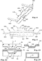
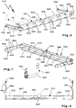
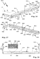
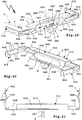
- the support assemblies 410-910 include cross members 411-911, from which side supports 412-912 protrude laterally.
- the side supports 412-912 are used for mounting on a schematically illustrated body K of a vehicle F, for example a passenger car with an internal combustion engine and / or an electric motor.
- the cross members 411-911 are often completely or partially hidden behind a rear apron or a rear bumper of the vehicle F.
- a holder 415-915 for a trailer coupling 451-951 is provided in the area of a transverse center 413 of the crossbeams 411-911.
- one or more brackets 415 'for a load carrier L can also be provided, for example.
- coupling parts M of the load carrier L can be fastened to the brackets 415 ', which have, for example, screw receptacles, plug-in receptacles or the like.
- the side members 412-912 are provided on the longitudinal ends 414 of the cross members 411-911 and are angled thereto, for example about 90 ° (larger or smaller angles are also easily possible.
- the cross member 511 of the carrier arrangement 510 are still Side carriers 512 'are drawn in, which are suitable, for example, for mounting on a rear end plate of the body of vehicle F, on the rear longitudinal ends of the longitudinal members of the body or the like.
- the longitudinal directions of extension of side members 512' and cross member 511 are approximately parallel.
- the cross-sections 411-911 are essentially U-shaped in their basic cross-section. Side walls 421-921 and side walls 492-922 protrude at an angle from a bottom wall or base wall 420-920.
- the base wall 420-920 is approximately vertical when the carrier arrangements 410-910 are installed on the vehicle F or in the installed state, while the side walls 421-921 and 492-922 run approximately horizontally and form upper and lower walls.
- the base wall 420-920 is thus, for example, a rear wall.
- the base wall 420-920 extends in each case to the longitudinal ends 414, that is to say to the side beams 412-912. However, the base wall 920 is wider in a central region 916 of the cross member 911 and has the two upper and lower side walls 921 and 992, while sections 923 of the base wall 920 narrower towards the longitudinal ends 414 have no upper and lower legs or side walls 921-922 exhibit. Among other things, this acts in the sense of a reinforcement or higher rigidity of the cross member 911 in the central region 916.
- the side walls 421-921, 422-922 are used for reinforcement, preferably in the area of the transverse center 413. Reinforcement deformations 430-930 are also provided, which improve the rigidity of the cross members 411-911.
- notch recesses 431-433, 531-533 are provided in a preferably rounded edge area (angular or polygonal would also be possible).
- the notch depressions 431, 531 arranged next to the holder 415, 515 are deeper than the notch depressions 432, 532 arranged next to them in the direction of the longitudinal ends 414, which in turn are deeper than the notch depressions 433, 533 located near the longitudinal ends 414.
- the rigidity of the cross member 411 and 511 is thus somewhat higher in the middle than transversely on the outside or in the region of the side supports 412 and 512.
- the notch depressions 431-433, 531-533 are approximately V-shaped, whereby they are embossed, so to speak, into the material of the cross member 411, 511.
- notch recesses 431-433, 531-533 and 434-934 is only to be understood as an example.
- the V-shape is not important. U-shaped depressions, depressions elsewhere, or the like, are also readily possible.
- the cross members 811 and 911 have depressions 835, 935 in their central regions which extend deeper backwards from the base wall 820 and 920 than depressions 836 and 936 which extend between the depressions 835, 935 and the side members 812 and 912 are located.
- the very deep depressions 835 and 935 have a greater stiffening effect than the less deep depressions 836, 936.
- the depressions 835, 935 and the depressions 836, 936 preferably extend in the respective longitudinal direction of the cross members 811 and 911.
- the depressions 835, 935 and the depressions 836, 936 have base walls or base walls 837, 937 or 838 and 938, between which and the base walls 820 and 920 of the cross members 811 and 911 side walls 839, 939 are provided.
- the crossbeams 811 and 911 are cross-sectionally Z-shaped or double-Z-shaped.
- the longitudinal end regions of the depressions 835, 935, 836, 936 are expediently rounded off.
- the side beams 412-912 are integrally connected to the cross beams 411-911.
- the side supports 412-912 are essentially plate-shaped.
- the side beams 412-912 have plate-shaped walls 440.
- Bores 441 are provided for mounting the side supports 412-912 on the body K of the vehicle F, through which holes screws or fastening bolts of this type can be inserted and screwed to the body K.
- the bores 441 are located on corresponding mounting areas 446 of the side carriers 412-912. While one bore 441 is near the free end of the side member 412-912, the other bore 441 is near the cross member 411-911, approximately in the area of the notch recesses 434-934.
- the deformation structure 444 bulges or bends, for example, as shown in the drawing in the event of a rear-end collision with the vehicle F inwards toward the body K or (not shown) away from the body K.
- the deformed deformation structures 444 are shown in solid lines, the undeformed side members 412-912 are shown in dashed lines.
- the cutouts 443 are located opposite one another, which is optional, so that, as it were, a cutout is provided with the cutouts 443 lying opposite one another.
- a rear impact on the cross member 411-911 i.e. an impact on the base wall 420-920
- the body K of the vehicle F is also deformed, and in addition to the deformation structure 444 there is also a region of the body K deforming in the event of a rear impact (not shown) and thus the relative spacing of screw holes or assembly areas of the body K for connection to the bolts, not shown, penetrating the bores 441 is reduced.
- the deformation structure 444 therefore also undergoes this deformation of the body K, so that the bolts (not shown) penetrating the bores 441 remain in the corresponding assembly areas or bores of the body K and do not tear out.
- the side carriers of the carrier arrangements 410-910 could also have at least local reinforcements, for example reinforcement sections 445 or the like, which is exemplary in FIG Figure 1 is drawn.
- the reinforcing sections 445 are provided, for example, in the area of the bores 441, so that the mounting areas 446 are locally reinforced.
- the reinforcing sections 445 are, for example, bent-over sections in the manner of the side walls 421, 422 which extend away from the wall 440.
- the brackets 415-915 can be provided integrally on the crossbeams 411-911 or can also comprise attached, inserted or similarly attached components.
- plug-in receptacle elements 517, 617, 717 and 817 are provided in the carrier arrangements 510-810.
- a plug-in end 553 of a coupling arm 552 of a trailer coupling 551 (for example, a plug-in end 553 of a coupling arm 551 ( Figure 7 ) can be inserted.
- Recesses 518-818 are provided on the side walls 521-821 and 522-822, the inner contour of which corresponds to the outer contour of the plug-in receptacle elements 517-817, so that these are held in a form-fitting manner.
- the plug-in receptacle elements 517-817 are glued, welded or otherwise firmly connected to the cross members 511-811, for example.
- screw connections are also possible, in particular in order not to impair the structure or material of the crossbeams 511-811.
- the carrier arrangements 410 and 910 comprise housings 450 and 950 for a trailer coupling 451, 951.
- the trailer coupling 451, 951 comprises, for example, a coupling arm 452, 952 which is provided on a coupling module 453 or is pivotably and / or displaceably mounted directly in the housing 950, for which purpose there is a bearing arrangement, not explained in more detail, with, for example, a pivot bearing and / or a sliding bearing.
- the coupling arms 452 and 952 are mounted between a working position A which projects rearward in front of the vehicle F and is intended for pulling a trailer and a rest position R which is preferably adjusted back behind a rear apron or a bumper of the vehicle F.
- drives for adjusting the coupling arms 452 and 952 are provided between these positions, for example integrated into the Coupling module 453.
- the coupling arm 452 and / or 952 it is also possible for the coupling arm 452 and / or 952 to be pivoted manually. That does not matter.
- controls for locking the coupling arms 452 and 952 in the working position A and / or the rest position R can be provided, which is also not shown in detail.
- the coupling module 453 comprises a module housing 454 in which, for example, one or more bearings (pivot bearings and / or sliding bearings) for the coupling arm 452 and / or a lock for the coupling arm 452 is present.
- bearings pivot bearings and / or sliding bearings
- the coupling module 453 or the module housing 454 can be inserted as a whole into the housing 450 and can also be locked and / or fastened there, for example by means of screws, bolts or the like.
- the coupling module 453 has an advantageous effect in terms of stiffening the housing 450.
- the housing 450 includes, for example, a rear wall 455 and side walls 456, which extend from the rear wall 455 to the base wall 420.
- a section of the base wall 420 opposite the rear wall 455 forms a front wall of the housing 450.
- An upper section of the upper side wall 421 forms, so to speak, the upper cover of the housing 450, so that apart from a lower opening 457 through which the module housing 454 can be inserted total closed housing is formed.
- the opening 457 is provided on a section 458 of the lower side wall 422.
- a coupling arm can also be mounted directly in the housing 450, for example a receiving sleeve, a bearing arrangement, motors and the like because the housing 450 offers sufficient space.
- the module housing 454 fits positively into the interior of the housing 450, so that a lower wall or lower cover of the module housing 454 closes the opening 457, so to speak, from below.
- seals e.g. Rubber elements, and the like other, easily possible.
- the module housing 454 can also be glued into the housing 450, for example.
- the housing 950 is provided by the central recess 935.
- sealing arrangement 957 which e.g. Includes sealing lips, provided.
- the carrier arrangements 410-910 each comprise integrally produced base bodies 460-960, which are produced from a single sheet metal plate 461-961 or their bodies 468-968.
- the base bodies 460-960 each include the cross members 411-911 and integrally molded thereon the side members 412-912.
- the housings 450, 950 are also provided for the brackets 415 and 915.
- the housings 450 and 950 are therefore also integral components of the base body 460-960, which makes manufacture easier.
- the sheet metal boards 461-961 consist for example of a steel sheet, aluminum sheet or the like.
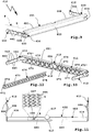
- the sheet metal plate 461 of the carrier arrangement 410 is shown as an example, which has already been cut out of a semifinished product or coil, for example by means of a laser, scissors, a punching tool or a tool arrangement which comprises one or more of the aforementioned cutting tools.
- the sheet metal plate 461 comprises, for example, a main section 462, from which the walls 440 of the side supports 412 project laterally in the longitudinal direction. Transversely to the direction of longitudinal extension, a section 463 provided to form the rear wall 455 and the side wall 456 protrude from the main section 462 and another section 464 opposite this, which later frames the opening 457, so to speak, or on which the opening 457 is formed.
- embossing lines 465 are already provided on the sheet metal plate 461, which are shown in dashed lines in the drawing and later facilitate the folding or folding or enable a targeted introduction of force. However, this is not necessary, but is an option.
- the base bodies 460-960 can already be designed in such a way by the reinforcement deformations or other measures that they have a stiffness profile or strength profile adapted to the voltage profile or an optimal introduction of force when the trailer is being pulled and / or in the event of a rear impact.
- a reinforcing body 670 is provided, which is inserted into an interior 624 of the cross member 611.
- the interior space 624 is delimited, for example, by the side walls 621 and 622 and the base wall 620.
- the reinforcing body 670 comprises, for example, a base wall 671 and side walls 672 protruding from it in a U-shape. These walls delimit an interior space in which a rib structure 673 is arranged, which has a stiffening effect.
- the rib structure 673 comprises, for example, ribs which are integrally connected to the side walls 672 and / or the base wall 671 and support them, so to speak.
- the rib structure 673 also acts in the sense of reinforcing the cross member 611, on which the reinforcing body 670 bears in a form-fitting manner or is arranged in a form-fitting manner in the interior.
- rib structures that are optimally adapted to a strength curve or stress curve can also be provided here, i.e. that, for example, a greater stiffening is desired in the area of the transverse center 613, while weaker ribs 675 and / or fewer ribs are provided along the outside or transversely outside, that is to say in the area of the longitudinal ends 414, and strong ribs 674 in the central area 413 Rib structure 673, for example, run diagonally between the side walls 672, in particular at an angle of approximately 45 ° thereto, and intersect, so that an X-shaped rib structure (in a plan view from behind) is provided.
- reinforcing body 670 there is at least one reinforcing body 670 between the holder 615 and the side supports 12 intended.
- the reinforcing body 670 is glued into the interior 624, for example.
- a rib structure or the like other reinforcing component can also be attached to a component manufactured according to the invention, i.e. e.g. can be molded from a sheet metal base body.
- a rib structure consists of plastic, which is also expediently the case with the reinforcing body 670.
- a concept that is particularly important in the one-piece, i.e. support arrangements 410-910 consisting of a base body 460-960 is advantageous, but also, for example in the case of multi-part support arrangements, not shown in the drawing, provides in particular local reinforcement of the support arrangement, where the rigidity and / or strength of the support arrangement should expediently be higher. Therefore, the concept described below is not applicable to the use of the advantageous basic bodies, which are made in one piece from a sheet metal plate, but can also be used with advantage in any other support arrangement, for example made of profile elements or the like.
- fiber material elements 480 for example triangular fiber material elements, are provided on the upper side wall 421 of the carrier arrangement 410 or of the cross member 411.
- This concept is also provided for the carrier arrangement 510, that is to say that triangular fiber material elements 580 are also provided on the cross member 511, so that an area between the center 513 and the side beams 512 is reinforced. It is also advantageous to provide reinforcement in the area of the holder 515.
- a fiber material element 581 is therefore provided there, which reinforces the holder 515 or the area around the recess 518, so to speak.
- the plug-in receptacle element 517 is therefore held particularly well by the upper side wall 521 and / or the lower side wall 522, which is optionally reinforced there with the aid of the fiber material element 581.
- a fiber material element 581 can be provided, for example, in one or both side walls 521 and / or 522.
- fiber material elements 680 are provided on the side next to the holder 615, which reinforce the upper side wall 621.
- the fiber material elements 680 comprise a mesh structure 683, a section A of which is shown enlarged.
- the meshing of fibers 684 ensures optimal reinforcement and tensile strength.
- a fiber material element 780 is glued into the interior 724 of the cross member 711.
- the fiber material element 780 is glued flatly on the inner sides of the base wall 720 and the upper and lower side walls 721 and 722, for example by means of a thermoplastic adhesive, which will become clear later.
- fiber material elements 880 are provided on the upper side wall 821.
- the fiber material elements 880 comprise, for example, a fiber mesh 885, which can be seen in an enlarged section B, with fibers 884, 886 which cross each other.
- fiber material elements can also be provided elsewhere, for example in the area of the recess 835, for example on the side wall 839 next to the holder 815.
- fiber material elements 881 are provided, which for example have a mesh structure such as the mesh structure 683 and / or a fiber mesh such as comprise the fiber braid 885.
- a fibrous material element 980 is also shown in the carrier arrangement 910, for example on the upper side wall 921 in the region of the holder 915. It would also be possible, for example, to provide one or more fibrous material elements around the cutout or the opening 957, which thus act locally reinforcing, where the opening 957 represents a certain weakening of the base body 960.
- Fiber arrangements 587-987 of the fiber material elements 580-980 or 581, 881, 981 include, for example, plastic fibers, in particular aramid fibers, and / or carbon fibers and / or Glass fibers or the like other non-organic materials that are tensile.
- plastic fibers in particular aramid fibers, and / or carbon fibers and / or Glass fibers or the like other non-organic materials that are tensile.
- other fibers are also possible, for example natural fibers made of sisal, coconut and the like.
- the fiber assemblies 587-987 can e.g. Include non-woven fiber material elements, in particular nonwovens and / or felts and / or thread or fiber fabrics, but also include a woven fabric and / or a fiber braid.
- the fiber assemblies 587-987 have e.g. fibers meshed with one another, in particular to form a knitted fabric and / or a knitted fabric.
- the fiber material elements 580-980 or 581, 881, 981 reinforce the base body 460-960, thus supporting components 488-988.
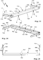
- the fiber material elements can be glued to the base body 460-960, for example by means of normal gluing, press gluing or the like. It is preferred to produce a type of composite sheet by means of a pressing tool, which is described in Figure 22 is shown schematically.
- a pressing tool 90 has a lower pressing element 91 and an upper pressing element 92.
- a receptacle 93 is provided on the lower pressing element 91, and a projection 94 corresponding to the recess or receptacle 93 is provided on the upper pressing element 92.
- the fiber material element 780 is to be glued there.
- the section 766 extends into the receptacle 93, while the fiber material element 780 still has a flat structure.
- the fiber material element 780 could already have a shape adapted to the receptacle 93, which it will later use according to the view Figure 23 Has. If the top Tool element or pressing element 92 is moved towards the lower pressing element 91 (represented by an arrow P), this presses the fiber material element 780 into the trough at the section 766, so that the fiber material element 780 assumes the contour of the trough or receptacle 93.
- the upper and / or lower pressing element 91/92 are heated (for example with a heater 99) so that an adhesive, for example a resin, a thermoplastic or the like, located in the fibers of the fiber material element 780 becomes adhesive and to the section 766 of the base body 760 adheres.
- an adhesive for example a resin, a thermoplastic or the like
- a further layer for example a sheet metal layer 767, can be pressed or stamped onto this layer structure comprising the base body 760 and the fiber material element 780, so that a kind of sandwich is produced.
- the fiber material element can also be configured in the manner of a sleeve, which is shown in Figure 24 becomes clear.
- a profile body 96 for example a tubular body, for example made of sheet metal material, is provided, which is surrounded by a fiber material element sleeve 97 and thus reinforced.
Landscapes
- Engineering & Computer Science (AREA)
- Transportation (AREA)
- Mechanical Engineering (AREA)
- Body Structure For Vehicles (AREA)
Claims (15)
- Ensemble de support pour un attelage de remorque (451 ; 551 ; 951) ou un support de charges (L), comprenant une traverse (411 - 911) et des supports latéraux (412 - 912) reliés à la traverse (411 - 911), destinés à être montés au niveau d'une partie arrière d'une carrosserie (K) d'un véhicule (F), ainsi qu'au moins une fixation (415- 915) disposée au niveau de la traverse (411 - 911) pour un attelage de remorque (451 ; 551 ; 951) ou pour une partie d'attelage (M) d'un support de charges (L), dans lequel l'ensemble de support (410 - 910) comprend un corps de base (460 - 960) produit par façonnage à partir d'une platine de tôle (461 - 961), comprenant la traverse (411 -911), dans lequel le corps de base (460 - 960) comprend en supplément de la traverse (411 - 911) au moins un support latéral (412 - 912) formé intégralement par le corps (468 - 968) de la platine de tôle (461 - 961) et/ou un boîtier (450 ; 950), formé intégralement par le corps (468 - 968) de la platine de tôle (461 - 961), de la fixation (415 - 915) pour l'attelage de remorque (451 ; 551 ; 951) ou la partie d'attelage de support de charges (M), caractérisé en ce que le corps de base (460 - 960) présente au moins un façonnage de renforcement (430 - 930), à savoir une moulure de renforcement.
- Ensemble de support selon la revendication 1, caractérisé en ce que la traverse (411 - 911) présente une section transversale en forme de U ou en forme de Z ou en forme de V ou en forme de W.
- Ensemble de support selon la revendication 1 ou 2, caractérisé en ce que le corps de base (460 - 960) est formé par un façonnage à froid et/ou un façonnage à chaud.
- Ensemble de support selon l'une quelconque des revendications précédentes, caractérisé en ce que le corps de base (460 - 960) ne présente aucune soudure, en particulier aucun cordon de soudure.
- Ensemble de support selon l'une quelconque des revendications précédentes, caractérisé en ce qu'au moins deux sections adjacentes du corps de base (460 - 960) se chevauchent et/ou sont reliées l'une à l'autre au moyen d'une feuillure et/ou d'une liaison par collage et/ou d'une liaison par soudage, en particulier d'un soudage par résistance.
- Ensemble de support selon l'une quelconque des revendications précédentes, caractérisé en ce que le corps de base (460 - 960) présente au moins un évidement pour la réduction de poids.
- Ensemble de support selon l'une quelconque des revendications précédentes, caractérisé en ce qu'un façonnage de renforcement (430 - 930) disposé dans la zone d'un milieu transversal (413) de la traverse (411 - 911) entre les supports latéraux (412 - 912) présente une profondeur s'étendant de manière à s'éloigner d'une face latérale de la traverse (411 - 911) plus grande qu'un façonnage de renforcement (430 - 930) prévu entre le milieu transversal (413) et un support latéral (412-912).
- Ensemble de support selon l'une quelconque des revendications précédentes, caractérisé en ce qu'au moins un façonnage de renforcement (430 - 930) configuré en particulier en tant que creux entaillé (431 - 934) est prévu au niveau d'une zone d'arête du corps de base (460 - 960).
- Ensemble de support selon l'une quelconque des revendications précédentes, caractérisé en ce que les supports latéraux (412 - 912) et la traverse (411 - 911) sont angulaires les uns par rapport aux autres, en particulier selon un angle d'environ 80 à 110° ou que les supports latéraux (412-912) et la traverse (411 - 911) sont parallèles et/ou sont en affleurement les uns avec les autres.
- Ensemble de support selon l'une quelconque des revendications précédentes ou selon le préambule de la revendication 1, caractérisé en ce qu'au moins un support latéral (412-912) présente une structure de déformation (444) pour la déformation planifiée en cas d'impact arrière sur le véhicule (F).
- Ensemble de support selon la revendication 10, caractérisé en ce que la structure de déformation (444) est prévue entre deux zones de montage (446) du support latéral (412 - 912) aux fins du montage au niveau de la carrosserie (K) du véhicule (F) de sorte que le support latéral (412 - 912) participe de manière correspondante à une déformation d'une section de la carrosserie (K), qui s'étend à côté de la structure de déformation (444).
- Ensemble de support selon l'une quelconque des revendications précédentes, caractérisé en ce que le corps de base (460 - 960) présente au moins une paroi de tôle épaisse en particulier de 1,5 à 3 mm.
- Ensemble de support selon l'une quelconque des revendications précédentes, caractérisé en ce qu'au moins un composant porteur (488 - 988) de l'ensemble de support (410 - 910), en particulier la traverse (411 - 911), est renforcé par au moins un élément en matériau à base de fibres (580 - 980 ; 581, 881, 981) présentant un ensemble de fibres (487 - 987).
- Ensemble de support selon la revendication 13, caractérisé en ce que l'au moins un élément en matériau à base de fibres (580 - 980 ; 581, 881, 981) comprend un élément en matériau à base de fibres non tissé (580 - 980 ; 581, 881, 981), en particulier un non-tissé et/ou un feutre et/ou un assemblage de fils ou de fibres et/ou un tissu et/ou un tressage de fibres et/ou que l'ensemble de fibres (487 - 987) comprend des fibres maillées les unes avec les autres, en particulier pour former un tissu à mailles et/ou un tricot et/ou l'au moins un élément en matériau à base de fibres (580 - 980 ; 581, 881, 981) est collé avec une colle au niveau du composant porteur (488 - 988) et/ou que l'au moins un élément en matériau à base de fibres (580 - 980 ; 581, 881, 981) présente un contour adapté à l'au moins un composant porteur (488 - 988), en particulier est configuré en tant qu'un composant de préimprégné ou un corps moulé à base de fibres.
- Procédé de fabrication d'un ensemble de support (410 - 910) pour un attelage de remorque (451 ; 551 ; 951) ou un support de charges (L), dans lequel l'ensemble de support (410 - 910) comprend une traverse (411 - 911) et des supports latéraux (412 - 912) reliés à la traverse (411 - 911), destinés à être montés au niveau d'une partie arrière d'une carrosserie (K) d'un véhicule (F), ainsi qu'au moins une fixation (415 - 915) disposée au niveau de la traverse (411 - 911) pour un attelage de remorque (451 ; 551 ; 951) ou pour une partie d'attelage (M) d'un support de charges (L), dans lequel le procédé comprend :
la fabrication d'une platine de tôle (461 - 961) par une découpe d'un matériau brut et le façonnage de la platine de tôle (461 - 961) de telle manière que l'ensemble de support (410-910) comprend un corps de base (460 - 960) produit par façonnage à partir de la platine de tôle (461 - 961), comprenant la traverse (411 - 911), et le corps de base (460 - 960) comprend, en supplément de la traverse (411 - 911), au moins un support latéral (412 - 912) formé intégralement par le corps de la platine de tôle (461 - 961) et/ou un boîtier (450 ; 950), formé intégralement par le corps (468 - 968) de la platine de tôle (461 - 961), de la fixation (415-915) pour l'attelage de remorque (451 ; 551 ; 951) ou la partie d'attelage de support de charges (M), caractérisé par la fabrication d'au moins un façonnage de renforcement (430 - 930), à savoir d'une moulure de renforcement, au niveau du corps de base (460 - 960).
Applications Claiming Priority (1)
| Application Number | Priority Date | Filing Date | Title |
|---|---|---|---|
| DE102012018547.2A DE102012018547A1 (de) | 2012-09-20 | 2012-09-20 | Trägeranordnung für eine Anhängekupplung oder einen Lastenträger aus einer Blechplatine |
Publications (3)
| Publication Number | Publication Date |
|---|---|
| EP2711209A2 EP2711209A2 (fr) | 2014-03-26 |
| EP2711209A3 EP2711209A3 (fr) | 2016-04-27 |
| EP2711209B1 true EP2711209B1 (fr) | 2020-06-17 |
Family
ID=49212544
Family Applications (1)
| Application Number | Title | Priority Date | Filing Date |
|---|---|---|---|
| EP13004437.3A Active EP2711209B1 (fr) | 2012-09-20 | 2013-09-12 | Agencement de support pour un attelage ou un support de charge doté d'une platine de tôle |
Country Status (3)
| Country | Link |
|---|---|
| EP (1) | EP2711209B1 (fr) |
| DE (1) | DE102012018547A1 (fr) |
| HU (1) | HUE049614T2 (fr) |
Families Citing this family (9)
| Publication number | Priority date | Publication date | Assignee | Title |
|---|---|---|---|---|
| DE102014014261A1 (de) * | 2014-09-25 | 2015-07-30 | Daimler Ag | Karosserie-Strukturelement für eine Fahrzeugkarosserie eines Kraftfahrzeugs |
| DE102014117886A1 (de) * | 2014-09-26 | 2016-03-31 | Westfalia-Automotive Gmbh | Trägeranordnung für eine Anhängekupplung oder einen Lastenträger |
| DE102018113909A1 (de) | 2018-02-27 | 2019-08-29 | Westfalia-Automotive Gmbh | Trägeranordnung eines Lastenträgers oder einer Kupplungseinrichtung |
| DE102019116502B3 (de) | 2019-06-18 | 2020-07-09 | Bayerische Motoren Werke Aktiengesellschaft | Querträger für einen Kraftwagen sowie die Anordnung eines Querträgers |
| GB2605614B (en) * | 2021-04-07 | 2023-11-22 | Draexlmaier Lisa Gmbh | Cross car beam for a vehicle |
| CN116331350A (zh) * | 2022-07-19 | 2023-06-27 | 赛赫智能设备(上海)股份有限公司 | 轻量级滑板式底盘 |
| DE102022119904A1 (de) * | 2022-08-08 | 2024-02-08 | ACPS Automotive GmbH | Anhängekupplung |
| DE102023125091A1 (de) * | 2023-09-16 | 2025-03-20 | Elringklinger Ag | Tragstrukturelement, Strukturbauteil, Transportvorrichtung, Straßenfahrzeug und Verfahren zur Herstellung eines Tragstrukturelements |
| DE102024101410A1 (de) * | 2024-01-18 | 2025-07-24 | ACPS Automotive GmbH | Querträger |
Citations (1)
| Publication number | Priority date | Publication date | Assignee | Title |
|---|---|---|---|---|
| EP2316670A1 (fr) * | 2009-11-03 | 2011-05-04 | Archetti Technology S.r.l. | Dispositif d'attelage de remorques légères pour véhicules |
Family Cites Families (11)
| Publication number | Priority date | Publication date | Assignee | Title |
|---|---|---|---|---|
| DE2812485A1 (de) * | 1978-03-22 | 1979-09-27 | Oris Metallbau Kg Riehle H | Anhaengerkupplung fuer kraftfahrzeuge, insbesondere fuer personenkraftwagen |
| US5853187A (en) * | 1996-11-22 | 1998-12-29 | Maier; James P. | Snowmobile hitch |
| AU734375B2 (en) * | 1997-08-21 | 2001-06-14 | Toray Industries, Inc. | Light metal/CFRP-made structural members |
| SE523794C2 (sv) | 2002-07-10 | 2004-05-18 | Monoflex Sweden Ab | Dragbalkskonstruktion |
| DE10327008B3 (de) * | 2003-06-12 | 2005-01-13 | Benteler Automobiltechnik Gmbh | Stoßfänger für ein Kraftfahrzeug |
| DE102004008741A1 (de) * | 2003-11-19 | 2005-07-14 | Alcan Technology & Management Ag | Stoßfängersystem |
| WO2006065117A1 (fr) * | 2004-12-14 | 2006-06-22 | Thule Towing Systems B.V. | Transporteur de charge pour automobiles |
| DE102006058602B4 (de) * | 2006-12-11 | 2016-06-30 | Benteler Automobiltechnik Gmbh | Verfahren zur Herstellung einer B-Säulenanordnung eines Kraftfahrzeugs |
| JP5095438B2 (ja) * | 2008-02-14 | 2012-12-12 | 富士重工業株式会社 | トレーラヒッチを備えた車体後部構造 |
| DE102010011296A1 (de) * | 2010-03-13 | 2010-10-28 | Daimler Ag | Querträger, insbesondere Biegequerträger, für eine Karosserie eines Kraftwagens sowie Verfahren zum Herstellen eines solchen Querträgers |
| US8322780B2 (en) * | 2010-12-20 | 2012-12-04 | Sabic Innovative Plastics Ip B.V. | Reinforced body in white and method of making and using the same |
-
2012
- 2012-09-20 DE DE102012018547.2A patent/DE102012018547A1/de active Pending
-
2013
- 2013-09-12 EP EP13004437.3A patent/EP2711209B1/fr active Active
- 2013-09-12 HU HUE13004437A patent/HUE049614T2/hu unknown
Patent Citations (1)
| Publication number | Priority date | Publication date | Assignee | Title |
|---|---|---|---|---|
| EP2316670A1 (fr) * | 2009-11-03 | 2011-05-04 | Archetti Technology S.r.l. | Dispositif d'attelage de remorques légères pour véhicules |
Also Published As
| Publication number | Publication date |
|---|---|
| EP2711209A3 (fr) | 2016-04-27 |
| HUE049614T2 (hu) | 2020-09-28 |
| EP2711209A2 (fr) | 2014-03-26 |
| DE102012018547A1 (de) | 2014-03-20 |
Similar Documents
| Publication | Publication Date | Title |
|---|---|---|
| EP2711209B1 (fr) | Agencement de support pour un attelage ou un support de charge doté d'une platine de tôle | |
| EP2569211B1 (fr) | Structure de carrosserie, en particulier structure de plancher, pour véhicule à moteur | |
| DE102016116787B3 (de) | B-Säule für eine Kraftfahrzeugkarosserie sowie Kraftfahrzeugkarosserie mit einer solchen B-Säule | |
| EP2025560B1 (fr) | Procédé de fabrication d'un agencement de pare-chocs d'un véhicule automobile | |
| DE102007030929A1 (de) | Achsträger für Kraftfahrzeuge | |
| EP2669100B1 (fr) | Agencement de support pour un attelage avec un élément de support durci par presse | |
| EP3271217A1 (fr) | Voiture particulière dotée d'une structure pour face avant | |
| EP1525133B1 (fr) | Structure de renfort de sol pour automobile | |
| EP3415349B1 (fr) | Dispositif de support pour une barre d'attelage et étrier de guidage dotés d'un élément de support multicomposant | |
| EP1597135B1 (fr) | Carrosserie avant ou arriere d'un vehicule et sa prise de masse | |
| EP2711208B1 (fr) | Agencement de support pour un attelage ou un support de charge doté d'un élément en matériau fibreux | |
| EP2878459B1 (fr) | Système de support pour un attelage avec un élément de support durci | |
| DE102013107179A1 (de) | Stoßabsorptionsvorrichtung für ein Kraftfahrzeug | |
| EP3427979B1 (fr) | Dispositif de support pour une barre d'attelage et étrier de guidage dotés d'un élément de support de forme étalon | |
| DE102011052291B4 (de) | Kraftfahrzeugbauteil sowie Verfahren zur Herstellung eines Kraftfahrzeugbauteils | |
| EP4494908B1 (fr) | Support de batterie | |
| DE202010017552U1 (de) | Karosseriestruktur, insbesondere Bodenstruktur, für ein Kraftfahrzeug | |
| DE102021123788B4 (de) | Kraftfahrzeug-Biegeträger | |
| DE102008033853A1 (de) | Fahrzeugkarosserie mit zumindest einer Zug-Druck-Strebe |
Legal Events
| Date | Code | Title | Description |
|---|---|---|---|
| PUAI | Public reference made under article 153(3) epc to a published international application that has entered the european phase |
Free format text: ORIGINAL CODE: 0009012 |
|
| AK | Designated contracting states |
Kind code of ref document: A2 Designated state(s): AL AT BE BG CH CY CZ DE DK EE ES FI FR GB GR HR HU IE IS IT LI LT LU LV MC MK MT NL NO PL PT RO RS SE SI SK SM TR |
|
| AX | Request for extension of the european patent |
Extension state: BA ME |
|
| PUAL | Search report despatched |
Free format text: ORIGINAL CODE: 0009013 |
|
| AK | Designated contracting states |
Kind code of ref document: A3 Designated state(s): AL AT BE BG CH CY CZ DE DK EE ES FI FR GB GR HR HU IE IS IT LI LT LU LV MC MK MT NL NO PL PT RO RS SE SI SK SM TR |
|
| AX | Request for extension of the european patent |
Extension state: BA ME |
|
| RIC1 | Information provided on ipc code assigned before grant |
Ipc: B60D 1/48 20060101AFI20160323BHEP |
|
| 17P | Request for examination filed |
Effective date: 20161021 |
|
| RBV | Designated contracting states (corrected) |
Designated state(s): AL AT BE BG CH CY CZ DE DK EE ES FI FR GB GR HR HU IE IS IT LI LT LU LV MC MK MT NL NO PL PT RO RS SE SI SK SM TR |
|
| STAA | Information on the status of an ep patent application or granted ep patent |
Free format text: STATUS: EXAMINATION IS IN PROGRESS |
|
| 17Q | First examination report despatched |
Effective date: 20180618 |
|
| GRAP | Despatch of communication of intention to grant a patent |
Free format text: ORIGINAL CODE: EPIDOSNIGR1 |
|
| STAA | Information on the status of an ep patent application or granted ep patent |
Free format text: STATUS: GRANT OF PATENT IS INTENDED |
|
| INTG | Intention to grant announced |
Effective date: 20200304 |
|
| GRAS | Grant fee paid |
Free format text: ORIGINAL CODE: EPIDOSNIGR3 |
|
| GRAA | (expected) grant |
Free format text: ORIGINAL CODE: 0009210 |
|
| STAA | Information on the status of an ep patent application or granted ep patent |
Free format text: STATUS: THE PATENT HAS BEEN GRANTED |
|
| AK | Designated contracting states |
Kind code of ref document: B1 Designated state(s): AL AT BE BG CH CY CZ DE DK EE ES FI FR GB GR HR HU IE IS IT LI LT LU LV MC MK MT NL NO PL PT RO RS SE SI SK SM TR |
|
| REG | Reference to a national code |
Ref country code: GB Ref legal event code: FG4D Free format text: NOT ENGLISH |
|
| REG | Reference to a national code |
Ref country code: CH Ref legal event code: EP |
|
| REG | Reference to a national code |
Ref country code: IE Ref legal event code: FG4D Free format text: LANGUAGE OF EP DOCUMENT: GERMAN |
|
| REG | Reference to a national code |
Ref country code: DE Ref legal event code: R096 Ref document number: 502013014800 Country of ref document: DE |
|
| REG | Reference to a national code |
Ref country code: AT Ref legal event code: REF Ref document number: 1280870 Country of ref document: AT Kind code of ref document: T Effective date: 20200715 |
|
| REG | Reference to a national code |
Ref country code: HU Ref legal event code: AG4A Ref document number: E049614 Country of ref document: HU |
|
| PG25 | Lapsed in a contracting state [announced via postgrant information from national office to epo] |
Ref country code: LT Free format text: LAPSE BECAUSE OF FAILURE TO SUBMIT A TRANSLATION OF THE DESCRIPTION OR TO PAY THE FEE WITHIN THE PRESCRIBED TIME-LIMIT Effective date: 20200617 Ref country code: GR Free format text: LAPSE BECAUSE OF FAILURE TO SUBMIT A TRANSLATION OF THE DESCRIPTION OR TO PAY THE FEE WITHIN THE PRESCRIBED TIME-LIMIT Effective date: 20200918 Ref country code: NO Free format text: LAPSE BECAUSE OF FAILURE TO SUBMIT A TRANSLATION OF THE DESCRIPTION OR TO PAY THE FEE WITHIN THE PRESCRIBED TIME-LIMIT Effective date: 20200917 Ref country code: FI Free format text: LAPSE BECAUSE OF FAILURE TO SUBMIT A TRANSLATION OF THE DESCRIPTION OR TO PAY THE FEE WITHIN THE PRESCRIBED TIME-LIMIT Effective date: 20200617 Ref country code: SE Free format text: LAPSE BECAUSE OF FAILURE TO SUBMIT A TRANSLATION OF THE DESCRIPTION OR TO PAY THE FEE WITHIN THE PRESCRIBED TIME-LIMIT Effective date: 20200617 |
|
| REG | Reference to a national code |
Ref country code: LT Ref legal event code: MG4D |
|
| REG | Reference to a national code |
Ref country code: NL Ref legal event code: MP Effective date: 20200617 |
|
| PG25 | Lapsed in a contracting state [announced via postgrant information from national office to epo] |
Ref country code: BG Free format text: LAPSE BECAUSE OF FAILURE TO SUBMIT A TRANSLATION OF THE DESCRIPTION OR TO PAY THE FEE WITHIN THE PRESCRIBED TIME-LIMIT Effective date: 20200917 Ref country code: LV Free format text: LAPSE BECAUSE OF FAILURE TO SUBMIT A TRANSLATION OF THE DESCRIPTION OR TO PAY THE FEE WITHIN THE PRESCRIBED TIME-LIMIT Effective date: 20200617 Ref country code: RS Free format text: LAPSE BECAUSE OF FAILURE TO SUBMIT A TRANSLATION OF THE DESCRIPTION OR TO PAY THE FEE WITHIN THE PRESCRIBED TIME-LIMIT Effective date: 20200617 Ref country code: HR Free format text: LAPSE BECAUSE OF FAILURE TO SUBMIT A TRANSLATION OF THE DESCRIPTION OR TO PAY THE FEE WITHIN THE PRESCRIBED TIME-LIMIT Effective date: 20200617 |
|
| PG25 | Lapsed in a contracting state [announced via postgrant information from national office to epo] |
Ref country code: AL Free format text: LAPSE BECAUSE OF FAILURE TO SUBMIT A TRANSLATION OF THE DESCRIPTION OR TO PAY THE FEE WITHIN THE PRESCRIBED TIME-LIMIT Effective date: 20200617 Ref country code: NL Free format text: LAPSE BECAUSE OF FAILURE TO SUBMIT A TRANSLATION OF THE DESCRIPTION OR TO PAY THE FEE WITHIN THE PRESCRIBED TIME-LIMIT Effective date: 20200617 |
|
| PG25 | Lapsed in a contracting state [announced via postgrant information from national office to epo] |
Ref country code: SM Free format text: LAPSE BECAUSE OF FAILURE TO SUBMIT A TRANSLATION OF THE DESCRIPTION OR TO PAY THE FEE WITHIN THE PRESCRIBED TIME-LIMIT Effective date: 20200617 Ref country code: EE Free format text: LAPSE BECAUSE OF FAILURE TO SUBMIT A TRANSLATION OF THE DESCRIPTION OR TO PAY THE FEE WITHIN THE PRESCRIBED TIME-LIMIT Effective date: 20200617 Ref country code: ES Free format text: LAPSE BECAUSE OF FAILURE TO SUBMIT A TRANSLATION OF THE DESCRIPTION OR TO PAY THE FEE WITHIN THE PRESCRIBED TIME-LIMIT Effective date: 20200617 Ref country code: PT Free format text: LAPSE BECAUSE OF FAILURE TO SUBMIT A TRANSLATION OF THE DESCRIPTION OR TO PAY THE FEE WITHIN THE PRESCRIBED TIME-LIMIT Effective date: 20201019 Ref country code: RO Free format text: LAPSE BECAUSE OF FAILURE TO SUBMIT A TRANSLATION OF THE DESCRIPTION OR TO PAY THE FEE WITHIN THE PRESCRIBED TIME-LIMIT Effective date: 20200617 Ref country code: CZ Free format text: LAPSE BECAUSE OF FAILURE TO SUBMIT A TRANSLATION OF THE DESCRIPTION OR TO PAY THE FEE WITHIN THE PRESCRIBED TIME-LIMIT Effective date: 20200617 Ref country code: IT Free format text: LAPSE BECAUSE OF FAILURE TO SUBMIT A TRANSLATION OF THE DESCRIPTION OR TO PAY THE FEE WITHIN THE PRESCRIBED TIME-LIMIT Effective date: 20200617 |
|
| PG25 | Lapsed in a contracting state [announced via postgrant information from national office to epo] |
Ref country code: SK Free format text: LAPSE BECAUSE OF FAILURE TO SUBMIT A TRANSLATION OF THE DESCRIPTION OR TO PAY THE FEE WITHIN THE PRESCRIBED TIME-LIMIT Effective date: 20200617 Ref country code: PL Free format text: LAPSE BECAUSE OF FAILURE TO SUBMIT A TRANSLATION OF THE DESCRIPTION OR TO PAY THE FEE WITHIN THE PRESCRIBED TIME-LIMIT Effective date: 20200617 Ref country code: IS Free format text: LAPSE BECAUSE OF FAILURE TO SUBMIT A TRANSLATION OF THE DESCRIPTION OR TO PAY THE FEE WITHIN THE PRESCRIBED TIME-LIMIT Effective date: 20201017 |
|
| REG | Reference to a national code |
Ref country code: DE Ref legal event code: R097 Ref document number: 502013014800 Country of ref document: DE |
|
| PLBE | No opposition filed within time limit |
Free format text: ORIGINAL CODE: 0009261 |
|
| STAA | Information on the status of an ep patent application or granted ep patent |
Free format text: STATUS: NO OPPOSITION FILED WITHIN TIME LIMIT |
|
| PG25 | Lapsed in a contracting state [announced via postgrant information from national office to epo] |
Ref country code: MC Free format text: LAPSE BECAUSE OF FAILURE TO SUBMIT A TRANSLATION OF THE DESCRIPTION OR TO PAY THE FEE WITHIN THE PRESCRIBED TIME-LIMIT Effective date: 20200617 Ref country code: DK Free format text: LAPSE BECAUSE OF FAILURE TO SUBMIT A TRANSLATION OF THE DESCRIPTION OR TO PAY THE FEE WITHIN THE PRESCRIBED TIME-LIMIT Effective date: 20200617 |
|
| REG | Reference to a national code |
Ref country code: CH Ref legal event code: PL |
|
| 26N | No opposition filed |
Effective date: 20210318 |
|
| GBPC | Gb: european patent ceased through non-payment of renewal fee |
Effective date: 20200917 |
|
| PG25 | Lapsed in a contracting state [announced via postgrant information from national office to epo] |
Ref country code: SI Free format text: LAPSE BECAUSE OF FAILURE TO SUBMIT A TRANSLATION OF THE DESCRIPTION OR TO PAY THE FEE WITHIN THE PRESCRIBED TIME-LIMIT Effective date: 20200617 |
|
| REG | Reference to a national code |
Ref country code: BE Ref legal event code: MM Effective date: 20200930 |
|
| PG25 | Lapsed in a contracting state [announced via postgrant information from national office to epo] |
Ref country code: LU Free format text: LAPSE BECAUSE OF NON-PAYMENT OF DUE FEES Effective date: 20200912 |
|
| PG25 | Lapsed in a contracting state [announced via postgrant information from national office to epo] |
Ref country code: BE Free format text: LAPSE BECAUSE OF NON-PAYMENT OF DUE FEES Effective date: 20200930 Ref country code: CH Free format text: LAPSE BECAUSE OF NON-PAYMENT OF DUE FEES Effective date: 20200930 Ref country code: GB Free format text: LAPSE BECAUSE OF NON-PAYMENT OF DUE FEES Effective date: 20200917 Ref country code: LI Free format text: LAPSE BECAUSE OF NON-PAYMENT OF DUE FEES Effective date: 20200930 Ref country code: IE Free format text: LAPSE BECAUSE OF NON-PAYMENT OF DUE FEES Effective date: 20200912 |
|
| PGFP | Annual fee paid to national office [announced via postgrant information from national office to epo] |
Ref country code: FR Payment date: 20210719 Year of fee payment: 9 |
|
| REG | Reference to a national code |
Ref country code: AT Ref legal event code: MM01 Ref document number: 1280870 Country of ref document: AT Kind code of ref document: T Effective date: 20200912 |
|
| PGFP | Annual fee paid to national office [announced via postgrant information from national office to epo] |
Ref country code: HU Payment date: 20210917 Year of fee payment: 9 |
|
| PG25 | Lapsed in a contracting state [announced via postgrant information from national office to epo] |
Ref country code: AT Free format text: LAPSE BECAUSE OF NON-PAYMENT OF DUE FEES Effective date: 20200912 |
|
| PG25 | Lapsed in a contracting state [announced via postgrant information from national office to epo] |
Ref country code: TR Free format text: LAPSE BECAUSE OF FAILURE TO SUBMIT A TRANSLATION OF THE DESCRIPTION OR TO PAY THE FEE WITHIN THE PRESCRIBED TIME-LIMIT Effective date: 20200617 Ref country code: MT Free format text: LAPSE BECAUSE OF FAILURE TO SUBMIT A TRANSLATION OF THE DESCRIPTION OR TO PAY THE FEE WITHIN THE PRESCRIBED TIME-LIMIT Effective date: 20200617 Ref country code: CY Free format text: LAPSE BECAUSE OF FAILURE TO SUBMIT A TRANSLATION OF THE DESCRIPTION OR TO PAY THE FEE WITHIN THE PRESCRIBED TIME-LIMIT Effective date: 20200617 |
|
| PG25 | Lapsed in a contracting state [announced via postgrant information from national office to epo] |
Ref country code: MK Free format text: LAPSE BECAUSE OF FAILURE TO SUBMIT A TRANSLATION OF THE DESCRIPTION OR TO PAY THE FEE WITHIN THE PRESCRIBED TIME-LIMIT Effective date: 20200617 |
|
| PG25 | Lapsed in a contracting state [announced via postgrant information from national office to epo] |
Ref country code: HU Free format text: LAPSE BECAUSE OF NON-PAYMENT OF DUE FEES Effective date: 20220913 Ref country code: FR Free format text: LAPSE BECAUSE OF NON-PAYMENT OF DUE FEES Effective date: 20220930 |
|
| PGFP | Annual fee paid to national office [announced via postgrant information from national office to epo] |
Ref country code: DE Payment date: 20250929 Year of fee payment: 13 |