EP2669487A2 - Aufgeladenes kombiniertes Kreislaufsystem mit Luftstrom-Bypass - Google Patents
Aufgeladenes kombiniertes Kreislaufsystem mit Luftstrom-Bypass Download PDFInfo
- Publication number
- EP2669487A2 EP2669487A2 EP13168441.7A EP13168441A EP2669487A2 EP 2669487 A2 EP2669487 A2 EP 2669487A2 EP 13168441 A EP13168441 A EP 13168441A EP 2669487 A2 EP2669487 A2 EP 2669487A2
- Authority
- EP
- European Patent Office
- Prior art keywords
- air
- combined cycle
- mass flow
- cycle system
- heat recovery
- Prior art date
- Legal status (The legal status is an assumption and is not a legal conclusion. Google has not performed a legal analysis and makes no representation as to the accuracy of the status listed.)
- Withdrawn
Links
- 238000000034 method Methods 0.000 claims abstract description 45
- 238000011084 recovery Methods 0.000 claims abstract description 17
- 230000015556 catabolic process Effects 0.000 claims description 5
- 238000001816 cooling Methods 0.000 claims description 5
- 238000006731 degradation reaction Methods 0.000 claims description 5
- 230000000153 supplemental effect Effects 0.000 claims 1
- 239000007789 gas Substances 0.000 description 22
- 230000008901 benefit Effects 0.000 description 7
- 238000012423 maintenance Methods 0.000 description 4
- 238000010586 diagram Methods 0.000 description 3
- 230000005611 electricity Effects 0.000 description 3
- 230000008569 process Effects 0.000 description 3
- 101100043112 Homo sapiens SERPINB3 gene Proteins 0.000 description 2
- 102100036383 Serpin B3 Human genes 0.000 description 2
- 239000000446 fuel Substances 0.000 description 2
- 230000006870 function Effects 0.000 description 2
- 238000007689 inspection Methods 0.000 description 2
- 230000003071 parasitic effect Effects 0.000 description 2
- QVGXLLKOCUKJST-UHFFFAOYSA-N atomic oxygen Chemical compound [O] QVGXLLKOCUKJST-UHFFFAOYSA-N 0.000 description 1
- 230000003190 augmentative effect Effects 0.000 description 1
- 238000004140 cleaning Methods 0.000 description 1
- 238000002485 combustion reaction Methods 0.000 description 1
- 238000010304 firing Methods 0.000 description 1
- 230000012447 hatching Effects 0.000 description 1
- 230000006872 improvement Effects 0.000 description 1
- 238000004519 manufacturing process Methods 0.000 description 1
- 238000012986 modification Methods 0.000 description 1
- 230000004048 modification Effects 0.000 description 1
- 239000001301 oxygen Substances 0.000 description 1
- 229910052760 oxygen Inorganic materials 0.000 description 1
- 230000000737 periodic effect Effects 0.000 description 1
- 238000010248 power generation Methods 0.000 description 1
- 238000010926 purge Methods 0.000 description 1
- 230000009467 reduction Effects 0.000 description 1
- 239000007787 solid Substances 0.000 description 1
- 238000011144 upstream manufacturing Methods 0.000 description 1
- 239000002918 waste heat Substances 0.000 description 1
Images

Classifications
-
- F—MECHANICAL ENGINEERING; LIGHTING; HEATING; WEAPONS; BLASTING
- F02—COMBUSTION ENGINES; HOT-GAS OR COMBUSTION-PRODUCT ENGINE PLANTS
- F02C—GAS-TURBINE PLANTS; AIR INTAKES FOR JET-PROPULSION PLANTS; CONTROLLING FUEL SUPPLY IN AIR-BREATHING JET-PROPULSION PLANTS
- F02C6/00—Plural gas-turbine plants; Combinations of gas-turbine plants with other apparatus; Adaptations of gas-turbine plants for special use
- F02C6/18—Plural gas-turbine plants; Combinations of gas-turbine plants with other apparatus; Adaptations of gas-turbine plants for special use using the waste heat of gas-turbine plants outside the plants themselves, e.g. gas-turbine power heat plants
-
- F—MECHANICAL ENGINEERING; LIGHTING; HEATING; WEAPONS; BLASTING
- F01—MACHINES OR ENGINES IN GENERAL; ENGINE PLANTS IN GENERAL; STEAM ENGINES
- F01D—NON-POSITIVE DISPLACEMENT MACHINES OR ENGINES, e.g. STEAM TURBINES
- F01D17/00—Regulating or controlling by varying flow
-
- F—MECHANICAL ENGINEERING; LIGHTING; HEATING; WEAPONS; BLASTING
- F01—MACHINES OR ENGINES IN GENERAL; ENGINE PLANTS IN GENERAL; STEAM ENGINES
- F01K—STEAM ENGINE PLANTS; STEAM ACCUMULATORS; ENGINE PLANTS NOT OTHERWISE PROVIDED FOR; ENGINES USING SPECIAL WORKING FLUIDS OR CYCLES
- F01K23/00—Plants characterised by more than one engine delivering power external to the plant, the engines being driven by different fluids
- F01K23/02—Plants characterised by more than one engine delivering power external to the plant, the engines being driven by different fluids the engine cycles being thermally coupled
- F01K23/06—Plants characterised by more than one engine delivering power external to the plant, the engines being driven by different fluids the engine cycles being thermally coupled combustion heat from one cycle heating the fluid in another cycle
- F01K23/10—Plants characterised by more than one engine delivering power external to the plant, the engines being driven by different fluids the engine cycles being thermally coupled combustion heat from one cycle heating the fluid in another cycle with exhaust fluid of one cycle heating the fluid in another cycle
- F01K23/101—Regulating means specially adapted therefor
-
- F—MECHANICAL ENGINEERING; LIGHTING; HEATING; WEAPONS; BLASTING
- F02—COMBUSTION ENGINES; HOT-GAS OR COMBUSTION-PRODUCT ENGINE PLANTS
- F02C—GAS-TURBINE PLANTS; AIR INTAKES FOR JET-PROPULSION PLANTS; CONTROLLING FUEL SUPPLY IN AIR-BREATHING JET-PROPULSION PLANTS
- F02C6/00—Plural gas-turbine plants; Combinations of gas-turbine plants with other apparatus; Adaptations of gas-turbine plants for special use
- F02C6/04—Gas-turbine plants providing heated or pressurised working fluid for other apparatus, e.g. without mechanical power output
-
- F—MECHANICAL ENGINEERING; LIGHTING; HEATING; WEAPONS; BLASTING
- F22—STEAM GENERATION
- F22B—METHODS OF STEAM GENERATION; STEAM BOILERS
- F22B1/00—Methods of steam generation characterised by form of heating method
- F22B1/02—Methods of steam generation characterised by form of heating method by exploitation of the heat content of hot heat carriers
- F22B1/18—Methods of steam generation characterised by form of heating method by exploitation of the heat content of hot heat carriers the heat carrier being a hot gas, e.g. waste gas such as exhaust gas of internal-combustion engines
- F22B1/1807—Methods of steam generation characterised by form of heating method by exploitation of the heat content of hot heat carriers the heat carrier being a hot gas, e.g. waste gas such as exhaust gas of internal-combustion engines using the exhaust gases of combustion engines
- F22B1/1815—Methods of steam generation characterised by form of heating method by exploitation of the heat content of hot heat carriers the heat carrier being a hot gas, e.g. waste gas such as exhaust gas of internal-combustion engines using the exhaust gases of combustion engines using the exhaust gases of gas-turbines
-
- Y—GENERAL TAGGING OF NEW TECHNOLOGICAL DEVELOPMENTS; GENERAL TAGGING OF CROSS-SECTIONAL TECHNOLOGIES SPANNING OVER SEVERAL SECTIONS OF THE IPC; TECHNICAL SUBJECTS COVERED BY FORMER USPC CROSS-REFERENCE ART COLLECTIONS [XRACs] AND DIGESTS
- Y02—TECHNOLOGIES OR APPLICATIONS FOR MITIGATION OR ADAPTATION AGAINST CLIMATE CHANGE
- Y02E—REDUCTION OF GREENHOUSE GAS [GHG] EMISSIONS, RELATED TO ENERGY GENERATION, TRANSMISSION OR DISTRIBUTION
- Y02E20/00—Combustion technologies with mitigation potential
- Y02E20/14—Combined heat and power generation [CHP]
-
- Y—GENERAL TAGGING OF NEW TECHNOLOGICAL DEVELOPMENTS; GENERAL TAGGING OF CROSS-SECTIONAL TECHNOLOGIES SPANNING OVER SEVERAL SECTIONS OF THE IPC; TECHNICAL SUBJECTS COVERED BY FORMER USPC CROSS-REFERENCE ART COLLECTIONS [XRACs] AND DIGESTS
- Y02—TECHNOLOGIES OR APPLICATIONS FOR MITIGATION OR ADAPTATION AGAINST CLIMATE CHANGE
- Y02E—REDUCTION OF GREENHOUSE GAS [GHG] EMISSIONS, RELATED TO ENERGY GENERATION, TRANSMISSION OR DISTRIBUTION
- Y02E20/00—Combustion technologies with mitigation potential
- Y02E20/16—Combined cycle power plant [CCPP], or combined cycle gas turbine [CCGT]
Definitions
- the subject matter disclosed herein relates to combined cycle power systems and more particularly to supercharged combined cycle systems with air flow bypass.
- Combined cycle power systems and cogeneration facilities utilize gas turbines to generate power. These gas turbines typically generate high temperature exhaust gases that are conveyed into a heat recovery steam generator (HRSG) that produces steam. The steam may be used to drive a steam turbine to generate more power and/or to provide steam for use in other processes.
- HRSG heat recovery steam generator
- Supercharging causing the inlet pressure to exceed the exhaust pressure
- Supercharged turbine systems typically include a variable speed supercharging fan located at the gas turbine inlet that is driven by steam energy derived from converting exhaust waste heat into steam. The supercharging fan is used to increase the air mass flow rate into the gas turbine so that the gas turbine shaft horsepower can be augmented.
- a problem with conventional supercharged combined cycle systems is that they are uneconomical due primarily to the prevailing "spark spread." Spark spread is the gross margin of a gas-fired power plant from selling a given amount of electricity minus the cost of fuel required to produce that given amount of electricity. Operational, maintenance, capital and other financial costs must be covered from the spark spread.
- Another problem with conventional supercharged systems is that controlling the inlet fan is difficult. In many cases, the return on investment of such systems is not attractive.
- Conventional supercharged combined cycle systems do not provide customers with sufficient system flexibility, output and efficiency over the system life cycle. Additionally, those systems require significant modifications and are sometimes not compatible with legacy systems.
- the invention resides in a combined cycle system including a gas turbine subsystem having a compressor and an output side that provides an exhaust, and a heat recovery steam generation subsystem having an inlet.
- An exhaust duct is coupled to the gas turbine system and the inlet for transporting the exhaust to the heat recovery steam generation system.
- the system also includes a controllable air stream source that produces an air flow and a ducting assembly coupled to the controllable air stream source that conveys at least a portion of the air flow to the compressor.
- a bypass coupled to the controllable air stream source and the exhaust duct adapted to selectively convey at least a portion of the air flow to the inlet is also provided.
- the invention resides in a supercharging system, the system including a forced draft fan providing a variable air flow.
- a duct that directs at least a portion of the air flow to a compressor and a bypass subsystem that diverts at least a portion of the air flow to a heat recovery steam generator are also provided.
- the system includes a control system coupled to the bypass subsystem and the forced draft fan.
- the invention resides in a method of operating a combined cycle system includes determining a first operating state and determining a desired operating state.
- the method includes determining a first mass flow quantity of air to be provided to a compressor and a second mass flow quantity of air to be provided to a heat recovery steam generator to achieve the desired operating state.
- the method includes providing source of controllable air flow, selectively conveying the first mass flow quantity of air into the compressor; and selectively conveying the second mass flow quantity of air to the heat recovery steam generator.
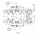
- FIG. 1 Illustrated in Figure 1 is a schematic illustration of a supercharged combined cycle system with air bypass (SCCAB system 11) in accordance with one embodiment of the present invention.
- the SCCAB system 11 includes a gas turbine subsystem 13 that in turn includes a compressor 15, having a compressor inlet 16, a combustor 17 and a turbine 19.
- An exhaust duct 21 may be coupled to the turbine 19 and a heat recovery steam generator subsystem (HRSG 23).
- the HRSG 23 recovers heat from exhaust gases from the turbine 19 that are conveyed through HRSG inlet 24 to generate steam.
- the HRSG 23 may also include a secondary burner 25 to provide additional energy to the HRSG 23.
- Some of the steam and exhaust from the HRSG 23 may be vented to stack 27 or used to drive a steam turbine 27 and provide additional power.
- the SCCAB system 11 may also include an inlet house and cooling system 29.
- the inlet house and cooling system 29 is used to cool and filter the air entering the compressor inlet 16 to increase power and avoid damage to the compressor 15.
- the SCCAB system 11 also includes a forced draft fan 30 used to create a positive pressure forcing air into the compressor 15.
- Forced draft fan 30 may have a fixed or variable blade fan (not shown) and an electric motor (not shown) to drive the blades.
- Forced draft fan 30 may be driven by a variable frequency drive (VFD 31) that controls the rotational speed of the electric motor by controlling the frequency of the electrical power supplied to the motor.
- VFD 31 provides a number of advantages, including energy savings from operating at lower than nominal speeds. Another advantage is that VFD 31 may be gradually ramped up to speed lessening the stress on the equipment.
- the forced draft fan 30 provides a controllable air stream source though a duct assembly 32 and may be used to increase the mass flow rate of air into the compressor 15. The quantity of air going into the compressor is controlled by the VFD 31.
- the compressor inlet 16 may be configured to accommodate slight positive pressure as compared to the slight negative pressure conventional design.
- the SCCAB system 11 may also include a bypass 33 (which may include external ducting) that diverts a portion of the air flow from forced draft fan 30 into the exhaust duct 21. This increased air flow provides additional oxygen to the secondary burner 25 to avoid flame out or less than optimal combustion.
- Bypass 33 may be provided with a flow sensor 35 and a damper valve 37 to control the airflow through the bypass 33.
- a control system 39 may be provided to receive data from flow sensor 35 and to control the damper valve 37 and the VFD 31. Control system 39 may be integrated into the larger control system used for operation control of SCCAB system 11.
- the airflow from the bypass is conveyed to the exhaust duct 21 where the temperature of the combined air and exhaust entering the HRSG 23 may be modulated.
- Illustrated in Figure 2 is another embodiment of a SCCAB system 11 that includes a pair of gas turbine subsystems 13.
- the exhaust of the pair of gas turbine subsystems 13 is used to drive a single steam turbine 27.
- an inlet house 41 is positioned upstream of the forced draft fan 30, and a cooling system 43, where the airflow from the fan may be cooled, is positioned downstream of the forced draft fan 30.
- the bypass 33 is coupled to the cooling system 43.
- the SCCAB system 11 provides increased air flow into the HRSG 23 resulting in a number of benefits.
- the SCCAB system 11 may provide an operator with the ability to optimize combined cycle plant flexibility, efficiency and lifecycle economics. For example, boosting the inlet pressure of the gas turbine subsystem 13 improves output and heat rate performance.
- the output performance of the SCCAB system 11 may be maintained flat (zero degradation) throughout the life cycle of SCCAB system 11 by increasing the level of supercharging (and parasitic load to drive the forced draft fan 30) over time commensurate with the degradation of SCCAB system 11.
- the use of the VFD 31 to power the forced draft fan 30 enables and substantially improves system efficiencies under partial-supercharge conditions.
- Another benefit that may be derived from the SCCAB system 11 is the expansion of the power generation to steam production ratio envelope. This may be accomplished by modulating the exhaust gas temperature at HRSG inlet 24 with air from the forced draft fan 30. Another benefit that may be derived from the SCCAB system 11 is an improved start up rate as a result of the reduction in the purge cycle (removal of built up gas).
- the SCCAB system 11 may also provide an improved load ramp rate resulting from the modulation of the exhaust temperature at the exhaust duct 21 with air from the forced draft fan 30 provided through the bypass 33.
- the forced draft fan 30 of the SCCAB system 11 also provides an effective means to force-cool the gas turbine subsystem 13 and HRSG 23, reducing maintenance outage time and improves system availability.
- the forced draft fan 30 provides comparable benefit for simple cycle and combined-cycle configurations for all heavy-duty gas turbine systems 13 delivering in the range of 20% output improvement under hot ambient conditions with modest capital cost.
- the SCCAB system 11 may implement a method of maintaining the output of a combined cycle plant over time (method 50) as illustrated with reference to Figures 3 - 4 .
- the method 50 may determine the current state (method element 51), and may determine a desired state (method element 53).
- the desired state may be to maintain a nominal output over time to compensate for performance losses. Performance losses typically arise as a result of wear of components in the gas turbine over time. These losses may be measured or calculated.
- the method 50 may determine the required increased air mass flow to maintain the desired output (method element 55). Based on that determination, the method 50 may adjust the air mass flow into the compressor inlet 16 (method element 57).
- the method 50 may adjust the combined air and exhaust mass flow into the HRSG inlet 24 (method element 59).
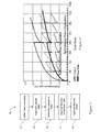
- Figure 4 illustrates the loss of output and heat rate over time (expressed in percentages) of a conventional combined cycle system and a SCCAB system 11.
- Gas turbines suffer a loss in output over time, as a result of wear of components in the gas turbine. This loss is due in part to increased turbine and compressor clearances and changes in surface finish and airfoil contour. Typically maintenance or compressor cleaning cannot recover this loss, rather the solution is the replacement of affected parts at recommended inspection intervals.
- the top curve (unbroken double line) illustrates the typical output loss of a conventional combined cycle system.
- the second curve illustrates the expected output loss with periodic inspections and routine maintenance.
- the lower curve shows that the output loss of an SCCAB system 11 may be maintained at near 0%.
- the heat rate degradation of a conventional combined cycle system may be significantly improved with an SCCAB system 11.
- Figure 5 illustrates a method of controlling the steam output of a SCCAB system 11 (method 60).
- Method 60 may initially determine the current state (method element 61). The method 60 may also determine the desired output and steam flow (method element 63). The method 60 may determine the required increased air flow (method element 65) to the compressor inlet 16 and the HRSG inlet 24. Method 60 may then adjust the air flow into the compressor inlet 16 (method element 67) and the combined exhaust and air flow into the HRSG inlet 24 (method element 69), to provide the desired steam output.
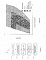
- Figure 6 illustrates expanded operating envelope to maintain constant steam flow.
- the vertical axis measures output in MW and horizontal axes measures steam mass flow.
- the interior area shows the envelope of a conventional combined cycle system.
- the envelope of an SCCA 11 is shown in diagonal cross hatching, and a larger area illustrates the performance of an SCCA 11 combined with secondary firing in the HRSG 23.
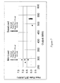
- Figure 7 is a chart that illustrates the improved operational performance of an SCCAB system 11 at a specific ambient temperature in comparison with conventional combined cycle systems at minimum and base loads.
- the horizontal axis measures output in MW and the vertical axis measures heat rate (the thermal energy (BTU's) from fuel required to produce one kWh of electricity).
- the chart illustrates the improved efficiency delivered by the SCCAB system 11.
Landscapes
- Engineering & Computer Science (AREA)
- Combustion & Propulsion (AREA)
- Chemical & Material Sciences (AREA)
- Mechanical Engineering (AREA)
- General Engineering & Computer Science (AREA)
- Life Sciences & Earth Sciences (AREA)
- Physics & Mathematics (AREA)
- Thermal Sciences (AREA)
- Sustainable Energy (AREA)
- Sustainable Development (AREA)
- Engine Equipment That Uses Special Cycles (AREA)
- Control Of Turbines (AREA)
- Air Supply (AREA)
- Structures Of Non-Positive Displacement Pumps (AREA)
Applications Claiming Priority (1)
| Application Number | Priority Date | Filing Date | Title |
|---|---|---|---|
| US13/485,160 US20130318941A1 (en) | 2012-05-31 | 2012-05-31 | Supercharged Combined Cycle System With Air Flow Bypass |
Publications (2)
| Publication Number | Publication Date |
|---|---|
| EP2669487A2 true EP2669487A2 (de) | 2013-12-04 |
| EP2669487A3 EP2669487A3 (de) | 2018-02-21 |
Family
ID=48484993
Family Applications (1)
| Application Number | Title | Priority Date | Filing Date |
|---|---|---|---|
| EP13168441.7A Withdrawn EP2669487A3 (de) | 2012-05-31 | 2013-05-20 | Aufgeladenes kombiniertes Kreislaufsystem mit Luftstrom-Bypass |
Country Status (5)
| Country | Link |
|---|---|
| US (1) | US20130318941A1 (de) |
| EP (1) | EP2669487A3 (de) |
| JP (1) | JP6334093B2 (de) |
| CN (1) | CN103452673B (de) |
| RU (1) | RU2013125139A (de) |
Cited By (1)
| Publication number | Priority date | Publication date | Assignee | Title |
|---|---|---|---|---|
| EP2740907A1 (de) * | 2012-12-05 | 2014-06-11 | General Electric Company | Laderampe und Anfahrsystem für kombiniertes Zykluskraftwerk und Betriebsverfahren |
Families Citing this family (16)
| Publication number | Priority date | Publication date | Assignee | Title |
|---|---|---|---|---|
| US9771864B2 (en) * | 2012-05-31 | 2017-09-26 | General Electric Company | Gas turbine compressor inlet pressurization and flow control system |
| JP6122775B2 (ja) * | 2013-12-26 | 2017-04-26 | 株式会社東芝 | 制御装置、及び起動方法 |
| US9273610B2 (en) * | 2014-05-20 | 2016-03-01 | Solar Turbines Incorporated | Starter/generator combination with all variable frequency drives |
| US10215070B2 (en) | 2015-06-29 | 2019-02-26 | General Electric Company | Power generation system exhaust cooling |
| US9850794B2 (en) | 2015-06-29 | 2017-12-26 | General Electric Company | Power generation system exhaust cooling |
| US9752503B2 (en) | 2015-06-29 | 2017-09-05 | General Electric Company | Power generation system exhaust cooling |
| US10087801B2 (en) | 2015-06-29 | 2018-10-02 | General Electric Company | Power generation system exhaust cooling |
| US9938874B2 (en) | 2015-06-29 | 2018-04-10 | General Electric Company | Power generation system exhaust cooling |
| US10060316B2 (en) | 2015-06-29 | 2018-08-28 | General Electric Company | Power generation system exhaust cooling |
| US9850818B2 (en) * | 2015-06-29 | 2017-12-26 | General Electric Company | Power generation system exhaust cooling |
| US9752502B2 (en) | 2015-06-29 | 2017-09-05 | General Electric Company | Power generation system exhaust cooling |
| US9856768B2 (en) | 2015-06-29 | 2018-01-02 | General Electric Company | Power generation system exhaust cooling |
| US10030558B2 (en) | 2015-06-29 | 2018-07-24 | General Electric Company | Power generation system exhaust cooling |
| US9840953B2 (en) | 2015-06-29 | 2017-12-12 | General Electric Company | Power generation system exhaust cooling |
| US10077694B2 (en) | 2015-06-29 | 2018-09-18 | General Electric Company | Power generation system exhaust cooling |
| US9964035B2 (en) * | 2015-12-15 | 2018-05-08 | General Electric Company | Power plant including exhaust gas coolant injection system and steam generating system via turbine extraction |
Family Cites Families (13)
| Publication number | Priority date | Publication date | Assignee | Title |
|---|---|---|---|---|
| DE2137977A1 (de) * | 1971-07-29 | 1973-02-15 | Aeg Kanis Turbinen | Energieerzeugungsanlage mit einem dampfkessel und einer gasturbine |
| JP2954456B2 (ja) * | 1993-07-14 | 1999-09-27 | 株式会社日立製作所 | 排気再循環型コンバインドプラント |
| FI96359C (fi) * | 1994-11-17 | 1998-08-26 | Tampella Power Oy | Menetelmä ja laitteisto kattilalaitoksen palamisilman säätämiseksi |
| EP1206634A4 (de) * | 1999-06-10 | 2005-10-12 | Enhanced Turbine Output Holdin | Aufladesystem für gasturbinen |
| US6430915B1 (en) * | 2000-08-31 | 2002-08-13 | Siemens Westinghouse Power Corporation | Flow balanced gas turbine power plant |
| US6442941B1 (en) * | 2000-09-11 | 2002-09-03 | General Electric Company | Compressor discharge bleed air circuit in gas turbine plants and related method |
| US6530224B1 (en) * | 2001-03-28 | 2003-03-11 | General Electric Company | Gas turbine compressor inlet pressurization system and method for power augmentation |
| US20030182944A1 (en) * | 2002-04-02 | 2003-10-02 | Hoffman John S. | Highly supercharged gas-turbine generating system |
| US7124591B2 (en) * | 2004-01-09 | 2006-10-24 | Siemens Power Generation, Inc. | Method for operating a gas turbine |
| US20070130952A1 (en) * | 2005-12-08 | 2007-06-14 | Siemens Power Generation, Inc. | Exhaust heat augmentation in a combined cycle power plant |
| JP2007182785A (ja) * | 2006-01-05 | 2007-07-19 | Mitsubishi Heavy Ind Ltd | ガスタービン及びガスタービンの起動方法並びに複合発電システム |
| EP2024620B1 (de) * | 2006-06-07 | 2015-07-29 | Alstom Technology Ltd | Verfahren zum betrieb einer gasturbine und kombikraftwerk zur durchführung des verfahrens |
| US9140184B2 (en) * | 2012-05-31 | 2015-09-22 | General Electric Company | Supercharged combined cycle system with air flow bypass to HRSG and fan |
-
2012
- 2012-05-31 US US13/485,160 patent/US20130318941A1/en not_active Abandoned
-
2013
- 2013-05-20 EP EP13168441.7A patent/EP2669487A3/de not_active Withdrawn
- 2013-05-28 JP JP2013111426A patent/JP6334093B2/ja not_active Expired - Fee Related
- 2013-05-30 RU RU2013125139/06A patent/RU2013125139A/ru not_active Application Discontinuation
- 2013-05-31 CN CN201310210295.0A patent/CN103452673B/zh not_active Expired - Fee Related
Non-Patent Citations (1)
| Title |
|---|
| None |
Cited By (1)
| Publication number | Priority date | Publication date | Assignee | Title |
|---|---|---|---|---|
| EP2740907A1 (de) * | 2012-12-05 | 2014-06-11 | General Electric Company | Laderampe und Anfahrsystem für kombiniertes Zykluskraftwerk und Betriebsverfahren |
Also Published As
| Publication number | Publication date |
|---|---|
| US20130318941A1 (en) | 2013-12-05 |
| JP2013249834A (ja) | 2013-12-12 |
| CN103452673B (zh) | 2017-03-01 |
| CN103452673A (zh) | 2013-12-18 |
| EP2669487A3 (de) | 2018-02-21 |
| RU2013125139A (ru) | 2014-12-10 |
| JP6334093B2 (ja) | 2018-05-30 |
Similar Documents
| Publication | Publication Date | Title |
|---|---|---|
| EP2669487A2 (de) | Aufgeladenes kombiniertes Kreislaufsystem mit Luftstrom-Bypass | |
| US9140184B2 (en) | Supercharged combined cycle system with air flow bypass to HRSG and fan | |
| US9567913B2 (en) | Systems and methods to extend gas turbine hot gas path parts with supercharged air flow bypass | |
| US20130318965A1 (en) | Supercharged Combined Cycle System With Air Flow Bypass To HRSG And Hydraulically Coupled Fan | |
| CN101078368B (zh) | 由使用空气抽取在欠频率运行期间运行燃气涡轮机的方法 | |
| EP2669492B1 (de) | System für druckbeaufschlagung und strömungskontrolle eines gasturbinenkompressoreinlasses | |
| US9822703B2 (en) | Fuel supply system | |
| US9239007B2 (en) | Gas turbine compressor inlet pressurization having a torque converter system | |
| CN103527320B (zh) | 操作带有单轴燃气涡轮的功率设备的方法及功率设备 | |
| US20110210555A1 (en) | Gas turbine driven electric power system with constant output through a full range of ambient conditions | |
| KR20190008346A (ko) | 산업용 가스터빈엔진을 새로 장착하기 위한 프로세스 및 새로 장착된 산업용 가스터빈엔진을 포함하는 파워플랜트 | |
| JP4923014B2 (ja) | 2軸式ガスタービン | |
| CN106351744B (zh) | 用于燃气涡轮的功率增大系统 | |
| CN101372914A (zh) | 扩大燃气轮机排放符合性的系统和方法 | |
| US20100175385A1 (en) | Method for Increasing Turndown Capability in an Electric Power Generation System | |
| US10036321B2 (en) | Systems and methods for utilizing gas turbine compartment ventilation discharge air | |
| EP2746554A2 (de) | Aufgeladenes GuD- Kraftwerk mit Luft-Bypass zum Abhitzedampferzeuger | |
| US20160245112A1 (en) | Method for operating a gas turbine arrangement | |
| JP3220859U (ja) | ガスタービンと空気タービン複合発電設備 | |
| US20110283708A1 (en) | Landfill gas utilization | |
| Ermolenko et al. | Construction of power-generating gas turbine units with the use of efficient thermal schemes |
Legal Events
| Date | Code | Title | Description |
|---|---|---|---|
| PUAI | Public reference made under article 153(3) epc to a published international application that has entered the european phase |
Free format text: ORIGINAL CODE: 0009012 |
|
| AK | Designated contracting states |
Kind code of ref document: A2 Designated state(s): AL AT BE BG CH CY CZ DE DK EE ES FI FR GB GR HR HU IE IS IT LI LT LU LV MC MK MT NL NO PL PT RO RS SE SI SK SM TR |
|
| AX | Request for extension of the european patent |
Extension state: BA ME |
|
| PUAL | Search report despatched |
Free format text: ORIGINAL CODE: 0009013 |
|
| AK | Designated contracting states |
Kind code of ref document: A3 Designated state(s): AL AT BE BG CH CY CZ DE DK EE ES FI FR GB GR HR HU IE IS IT LI LT LU LV MC MK MT NL NO PL PT RO RS SE SI SK SM TR |
|
| AX | Request for extension of the european patent |
Extension state: BA ME |
|
| RIC1 | Information provided on ipc code assigned before grant |
Ipc: F01D 17/00 20060101ALI20180118BHEP Ipc: F02C 1/00 20060101AFI20180118BHEP Ipc: F01K 23/10 20060101ALI20180118BHEP |
|
| 17P | Request for examination filed |
Effective date: 20180821 |
|
| RBV | Designated contracting states (corrected) |
Designated state(s): AL AT BE BG CH CY CZ DE DK EE ES FI FR GB GR HR HU IE IS IT LI LT LU LV MC MK MT NL NO PL PT RO RS SE SI SK SM TR |
|
| 17Q | First examination report despatched |
Effective date: 20190314 |
|
| STAA | Information on the status of an ep patent application or granted ep patent |
Free format text: STATUS: THE APPLICATION IS DEEMED TO BE WITHDRAWN |
|
| 18D | Application deemed to be withdrawn |
Effective date: 20190725 |