EP2746554A2 - Aufgeladenes GuD- Kraftwerk mit Luft-Bypass zum Abhitzedampferzeuger - Google Patents
Aufgeladenes GuD- Kraftwerk mit Luft-Bypass zum Abhitzedampferzeuger Download PDFInfo
- Publication number
- EP2746554A2 EP2746554A2 EP13198226.6A EP13198226A EP2746554A2 EP 2746554 A2 EP2746554 A2 EP 2746554A2 EP 13198226 A EP13198226 A EP 13198226A EP 2746554 A2 EP2746554 A2 EP 2746554A2
- Authority
- EP
- European Patent Office
- Prior art keywords
- air
- prime mover
- fan
- mass flow
- gas turbine
- Prior art date
- Legal status (The legal status is an assumption and is not a legal conclusion. Google has not performed a legal analysis and makes no representation as to the accuracy of the status listed.)
- Withdrawn
Links
- 238000011084 recovery Methods 0.000 claims abstract description 19
- 230000006698 induction Effects 0.000 claims abstract description 12
- 238000000034 method Methods 0.000 claims description 48
- MROJXXOCABQVEF-UHFFFAOYSA-N Actarit Chemical compound CC(=O)NC1=CC=C(CC(O)=O)C=C1 MROJXXOCABQVEF-UHFFFAOYSA-N 0.000 claims 9
- 239000007789 gas Substances 0.000 description 64
- 230000008901 benefit Effects 0.000 description 21
- 238000012423 maintenance Methods 0.000 description 10
- 238000001816 cooling Methods 0.000 description 8
- 230000015556 catabolic process Effects 0.000 description 7
- 238000006731 degradation reaction Methods 0.000 description 7
- 239000000446 fuel Substances 0.000 description 6
- 238000004519 manufacturing process Methods 0.000 description 5
- 230000008569 process Effects 0.000 description 5
- 238000010586 diagram Methods 0.000 description 3
- 230000005611 electricity Effects 0.000 description 3
- 230000006870 function Effects 0.000 description 3
- 230000006872 improvement Effects 0.000 description 3
- 238000010248 power generation Methods 0.000 description 3
- 238000002485 combustion reaction Methods 0.000 description 2
- 238000007689 inspection Methods 0.000 description 2
- 230000003071 parasitic effect Effects 0.000 description 2
- QVGXLLKOCUKJST-UHFFFAOYSA-N atomic oxygen Chemical compound [O] QVGXLLKOCUKJST-UHFFFAOYSA-N 0.000 description 1
- 230000003190 augmentative effect Effects 0.000 description 1
- 230000008859 change Effects 0.000 description 1
- 238000004140 cleaning Methods 0.000 description 1
- 238000013500 data storage Methods 0.000 description 1
- 230000007423 decrease Effects 0.000 description 1
- 238000013461 design Methods 0.000 description 1
- 230000005674 electromagnetic induction Effects 0.000 description 1
- 239000000284 extract Substances 0.000 description 1
- 238000010304 firing Methods 0.000 description 1
- 230000012447 hatching Effects 0.000 description 1
- 238000012986 modification Methods 0.000 description 1
- 230000004048 modification Effects 0.000 description 1
- 238000012544 monitoring process Methods 0.000 description 1
- 239000001301 oxygen Substances 0.000 description 1
- 229910052760 oxygen Inorganic materials 0.000 description 1
- 230000000737 periodic effect Effects 0.000 description 1
- 238000010926 purge Methods 0.000 description 1
- 230000009467 reduction Effects 0.000 description 1
- 239000007787 solid Substances 0.000 description 1
- 230000002459 sustained effect Effects 0.000 description 1
- 238000011144 upstream manufacturing Methods 0.000 description 1
- 239000002918 waste heat Substances 0.000 description 1
Images



Classifications
-
- F—MECHANICAL ENGINEERING; LIGHTING; HEATING; WEAPONS; BLASTING
- F02—COMBUSTION ENGINES; HOT-GAS OR COMBUSTION-PRODUCT ENGINE PLANTS
- F02C—GAS-TURBINE PLANTS; AIR INTAKES FOR JET-PROPULSION PLANTS; CONTROLLING FUEL SUPPLY IN AIR-BREATHING JET-PROPULSION PLANTS
- F02C6/00—Plural gas-turbine plants; Combinations of gas-turbine plants with other apparatus; Adaptations of gas-turbine plants for special use
- F02C6/18—Plural gas-turbine plants; Combinations of gas-turbine plants with other apparatus; Adaptations of gas-turbine plants for special use using the waste heat of gas-turbine plants outside the plants themselves, e.g. gas-turbine power heat plants
-
- F—MECHANICAL ENGINEERING; LIGHTING; HEATING; WEAPONS; BLASTING
- F01—MACHINES OR ENGINES IN GENERAL; ENGINE PLANTS IN GENERAL; STEAM ENGINES
- F01K—STEAM ENGINE PLANTS; STEAM ACCUMULATORS; ENGINE PLANTS NOT OTHERWISE PROVIDED FOR; ENGINES USING SPECIAL WORKING FLUIDS OR CYCLES
- F01K23/00—Plants characterised by more than one engine delivering power external to the plant, the engines being driven by different fluids
- F01K23/02—Plants characterised by more than one engine delivering power external to the plant, the engines being driven by different fluids the engine cycles being thermally coupled
- F01K23/06—Plants characterised by more than one engine delivering power external to the plant, the engines being driven by different fluids the engine cycles being thermally coupled combustion heat from one cycle heating the fluid in another cycle
- F01K23/10—Plants characterised by more than one engine delivering power external to the plant, the engines being driven by different fluids the engine cycles being thermally coupled combustion heat from one cycle heating the fluid in another cycle with exhaust fluid of one cycle heating the fluid in another cycle
- F01K23/101—Regulating means specially adapted therefor
-
- F—MECHANICAL ENGINEERING; LIGHTING; HEATING; WEAPONS; BLASTING
- F02—COMBUSTION ENGINES; HOT-GAS OR COMBUSTION-PRODUCT ENGINE PLANTS
- F02C—GAS-TURBINE PLANTS; AIR INTAKES FOR JET-PROPULSION PLANTS; CONTROLLING FUEL SUPPLY IN AIR-BREATHING JET-PROPULSION PLANTS
- F02C9/00—Controlling gas-turbine plants; Controlling fuel supply in air- breathing jet-propulsion plants
- F02C9/16—Control of working fluid flow
- F02C9/18—Control of working fluid flow by bleeding, bypassing or acting on variable working fluid interconnections between turbines or compressors or their stages
-
- F—MECHANICAL ENGINEERING; LIGHTING; HEATING; WEAPONS; BLASTING
- F22—STEAM GENERATION
- F22B—METHODS OF STEAM GENERATION; STEAM BOILERS
- F22B1/00—Methods of steam generation characterised by form of heating method
- F22B1/02—Methods of steam generation characterised by form of heating method by exploitation of the heat content of hot heat carriers
- F22B1/18—Methods of steam generation characterised by form of heating method by exploitation of the heat content of hot heat carriers the heat carrier being a hot gas, e.g. waste gas such as exhaust gas of internal-combustion engines
- F22B1/1807—Methods of steam generation characterised by form of heating method by exploitation of the heat content of hot heat carriers the heat carrier being a hot gas, e.g. waste gas such as exhaust gas of internal-combustion engines using the exhaust gases of combustion engines
- F22B1/1815—Methods of steam generation characterised by form of heating method by exploitation of the heat content of hot heat carriers the heat carrier being a hot gas, e.g. waste gas such as exhaust gas of internal-combustion engines using the exhaust gases of combustion engines using the exhaust gases of gas-turbines
-
- Y—GENERAL TAGGING OF NEW TECHNOLOGICAL DEVELOPMENTS; GENERAL TAGGING OF CROSS-SECTIONAL TECHNOLOGIES SPANNING OVER SEVERAL SECTIONS OF THE IPC; TECHNICAL SUBJECTS COVERED BY FORMER USPC CROSS-REFERENCE ART COLLECTIONS [XRACs] AND DIGESTS
- Y02—TECHNOLOGIES OR APPLICATIONS FOR MITIGATION OR ADAPTATION AGAINST CLIMATE CHANGE
- Y02E—REDUCTION OF GREENHOUSE GAS [GHG] EMISSIONS, RELATED TO ENERGY GENERATION, TRANSMISSION OR DISTRIBUTION
- Y02E20/00—Combustion technologies with mitigation potential
- Y02E20/14—Combined heat and power generation [CHP]
-
- Y—GENERAL TAGGING OF NEW TECHNOLOGICAL DEVELOPMENTS; GENERAL TAGGING OF CROSS-SECTIONAL TECHNOLOGIES SPANNING OVER SEVERAL SECTIONS OF THE IPC; TECHNICAL SUBJECTS COVERED BY FORMER USPC CROSS-REFERENCE ART COLLECTIONS [XRACs] AND DIGESTS
- Y02—TECHNOLOGIES OR APPLICATIONS FOR MITIGATION OR ADAPTATION AGAINST CLIMATE CHANGE
- Y02E—REDUCTION OF GREENHOUSE GAS [GHG] EMISSIONS, RELATED TO ENERGY GENERATION, TRANSMISSION OR DISTRIBUTION
- Y02E20/00—Combustion technologies with mitigation potential
- Y02E20/16—Combined cycle power plant [CCPP], or combined cycle gas turbine [CCGT]
Definitions
- the subject matter disclosed herein relates to combined cycle power systems and more particularly to supercharged combined cycle systems with air flow bypass.
- Combined cycle power systems and cogeneration facilities utilize gas turbines to generate power. These gas turbines typically generate high temperature exhaust gases that are conveyed into a heat recovery steam generator (HRSG) that produces steam. The steam may be used to drive a steam turbine to generate more power and/or to provide steam for use in other processes.
- HRSG heat recovery steam generator
- Supercharging causing the inlet pressure to exceed the ambient pressure
- Supercharged turbine systems typically include a variable speed supercharging fan located at the gas turbine inlet that is driven by steam energy derived from converting exhaust waste heat into steam. The supercharging fan is used to increase the air mass flow rate into the gas turbine so that the gas turbine shaft horsepower can be augmented.
- a problem with conventional supercharged combined cycle systems is that they are uneconomical due primarily to the prevailing "spark spread." Spark spread is the gross margin of a gas-fired power plant from selling a given amount of electricity minus the cost of fuel required to produce that given amount of electricity. Operational, maintenance, capital and other financial costs must be covered from the spark spread.
- Another problem with conventional supercharged systems is that controlling the inlet fan is difficult. In many cases, the return on investment of such systems is not attractive.
- Conventional supercharged combined cycle systems do not provide customers with sufficient system flexibility, output and efficiency over the system life cycle. Additionally, those systems require significant modifications and are sometimes not compatible with legacy systems.
- the invention relates to a combined cycle system including a gas turbine subsystem having a compressor and an output side that provides an exhaust, and a heat recovery steam generation subsystem having an inlet.
- An exhaust duct is coupled to the gas turbine system and the inlet for transporting the exhaust to the heat recovery steam generation system.
- the system also includes a controllable air stream source that produces an air flow and a ducting assembly coupled to the controllable air stream source that conveys at least a portion of the air flow to the compressor.
- a bypass coupled to the controllable air stream source and the exhaust duct adapted to selectively convey at least a portion of the air flow to the inlet is also provided.
- a supercharging system including a forced draft fan providing a variable air flow.
- a duct that directs at least a portion of the air flow to a compressor and a bypass subsystem that diverts at least a portion of the air flow to a heat recovery steam generator are also provided.
- the system includes a control system coupled to the bypass subsystem and the forced draft fan.
- a method of operating a combined cycle system includes determining a first operating state and determining a desired operating state.
- the method includes determining a first mass flow quantity of air to be provided to a compressor and a second mass flow quantity of air to be provided to a heat recovery steam generator to achieve the desired operating state.
- the method includes providing source of controllable air flow, selectively conveying the first mass flow quantity of air into the compressor; and selectively conveying the second mass flow quantity of air to the heat recovery steam generator.
- a combined cycle system has a gas turbine subsystem having a compressor and an output side that provides an exhaust, an exhaust duct coupled to the gas turbine subsystem and a heat recovery steam generation subsystem coupled to the exhaust duct.
- a fan that produces an air flow is driven by a prime mover having a drive exhaust.
- a ducting assembly coupled to the fan that conveys at least a portion of the air flow to the compressor is provided.
- a main bypass coupled to the fan and the exhaust duct adapted to selectively convey at least a portion of the air flow to exhaust duct; and a drive bypass coupled to the fan and the prime mover adapted to selectively convey at least a portion of the air flow to the prime mover are provided.
- the prime mover may be one of an aeroderivative gas turbine, a gas turbine, a reciprocating engine, a steam turbine and an induction motor.
- a supercharging system having a fan providing an air flow and a prime mover coupled to the fan.
- the supercharging system also includes a duct that directs a first portion of the air flow to a gas turbine system, a main bypass subsystem that diverts a second portion of the air flow to a heat recovery steam generator, and a drive bypass subsystem that diverts a third portion of the air flow to the prime mover.
- a method of operating a combined cycle system includes the steps of determining a first operating state, and determining a desired operating state.
- the method includes determining a first mass flow quantity of air to be provided to a gas turbine compressor to achieve the desired operating state, determining a second mass flow quantity of air to be provided to a heat recovery steam generator to achieve the desired operating state, and determining a third mass flow quantity of air to be provided to a prime mover to achieve the desired operating state.
- the method also includes the steps of driving a fan with a prime mover to provide an air flow, and dividing the air flow into a first mass flow portion associated with the first mass flow quantity of air, a second mass flow portion associated with the second mass flow quantity of air, and a third mass flow portion associated with the third mass flow quantity of air.
- the method further includes conveying the first mass flow portion into a compressor, conveying the second mass flow quantity of air to the heat recovery steam generator, and conveying the third mass flow quantity of air to the prime mover.
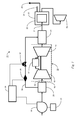
- FIG. 1 Illustrated in Figure 1 is a schematic illustration of a supercharged combined cycle system with air bypass (SCCAB system 11) in accordance with one embodiment of the present invention.
- the SCCAB system 11 includes a gas turbine subsystem 13 that in turn includes a compressor 15, having a compressor inlet 16, a combustor 17 and a turbine 19.
- An exhaust duct 21 may be coupled to the turbine 19 and a heat recovery steam generator subsystem (HRSG 23).
- the HRSG 23 recovers heat from exhaust gases from the turbine 19 that are conveyed through HRSG inlet 24 to generate steam.
- the HRSG 23 may also include a secondary burner 25 to provide additional energy to the HRSG 23.
- Some of the steam and exhaust from the HRSG 23 may be vented to stack 27 or used to drive a steam turbine 26 and provide additional power.
- the SCCAB system 11 may also include an inlet house and cooling system 29.
- the inlet house and cooling system 29 is used to cool and filter the air entering the compressor inlet 16 to increase power and avoid damage to the compressor 15.
- the SCCAB system 11 also includes a forced draft fan 30 used to create a positive pressure forcing air into the compressor 15.
- Forced draft fan 30 may have a fixed or variable blade fan (not shown) and an electric motor (not shown) to drive the blades.
- Forced draft fan 30 may be driven by a prime mover 31.
- the forced draft fan 30 provides a controllable air stream source though a duct assembly 32 and may be used to increase the mass flow rate of air into the compressor 15.
- the quantity of air going into the compressor is controlled by the prime mover 31.
- the compressor inlet 16 may be configured to accommodate slight positive pressure as compared to the slight negative pressure conventional design.
- the SCCAB system 11 may also include a bypass 33 (which may include external ducting) that diverts a portion of the air flow from forced draft fan 30 into the exhaust duct 21. This increased air flow provides additional oxygen to the secondary burner 25 to avoid flame out or less than optimal combustion.
- Bypass 33 may be provided with a flow sensor 35 and a damper valve 37 to control the airflow through the bypass 33.
- a control system 39 may be provided to receive data from flow sensor 35 and to control the damper valve 37 and the prime mover 31. Control system 39 may be integrated into the larger control system used for operation control of SCCAB system 11.
- the airflow from the bypass is conveyed to the exhaust duct 21 where the temperature of the combined air and exhaust entering the HRSG 23 may be modulated.
- Illustrated in Figure 2 is another embodiment of a SCCAB system 11 that includes a pair of gas turbine subsystem(s) 13.
- the exhaust of the pair of gas turbine subsystem(s) 13 is used to drive a steam turbine 26.
- an inlet house 41 is positioned upstream of the forced draft fan 30, and a cooling system 43, where the airflow from the fan may be cooled, is positioned downstream of the forced draft fan 30.
- the bypass 33 is coupled to the cooling system 43.
- the SCCAB system 11 provides increased air flow into the HRSG 23 resulting in a number of benefits.
- the SCCAB system 11 may provide an operator with the ability to optimize combined cycle plant flexibility, efficiency and lifecycle economics. For example, boosting the inlet pressure of the gas turbine subsystem 13 improves output and heat rate performance.
- the output performance of the SCCAB system 11 may be maintained flat (zero degradation) throughout the life cycle of SCCAB system 11 by increasing the level of supercharging (and parasitic load to drive the forced draft fan 30) over time commensurate with the degradation of SCCAB system 11.
- Another benefit that may be derived from the SCCAB system 11 is the expansion of the power generation to steam production ratio envelope.
- the SCCAB system 11 may also provide an improved load ramp rate resulting from the modulation of the exhaust temperature at the exhaust duct 21 with air from the forced draft fan 30 provided through the bypass 33.
- the forced draft fan 30 of the SCCAB system 11 also provides an effective means to force-cool the gas turbine subsystem 13 and HRSG 23, reducing maintenance outage time and improves system availability.
- the forced draft fan 30 provides comparable benefit for simple cycle and combined-cycle configurations for all gas turbine subsystem(s) 13 delivering in the range of 20% output improvement under hot ambient conditions with modest capital cost.
- the SCCAB system 11 may implement a method of maintaining the output of a combined cycle plant over time (method 50) as illustrated with reference to Figure 3 .
- the method 50 may determine the current state, and in step 53, the method 50 may determine a desired state.
- the desired state may be to maintain a nominal output over time to compensate for performance losses. Performance losses typically arise as a result of wear of components in the gas turbine over time. These losses may be measured or calculated.
- the method 50 may determine the required increased air mass flow to maintain the desired output. Based on that determination, the method 50 may, in step 57 adjust the air mass flow into the compressor inlet 16. In step 59, the method 50 may adjust the combined air and exhaust mass flow into the HRSG inlet 24.
- Figure 4 illustrates the loss of output and heat rate over time (expressed in percentages) of a conventional combined cycle system and a SCCAB system 11.
- Gas turbines suffer a loss in output over time, as a result of wear of components in the gas turbine. This loss is due in part to increased turbine and compressor clearances and changes in surface finish and airfoil contour. Typically maintenance or compressor cleaning cannot recover this loss, rather the solution is the replacement of affected parts at recommended inspection intervals.
- the top curve (unbroken double line) illustrates the typical output loss of a conventional combined cycle system.
- the second curve illustrates the expected output loss with periodic inspections and routine maintenance.
- the lower curve shows that the output loss of an SCCAB system 11 may be maintained at near 0%.
- the heat rate degradation of a conventional combined cycle system may be significantly improved with an SCCAB system 11.
- Figure 5 illustrates a method of controlling the steam output of a SCCAB system 11 (method 60).
- method 60 may initially determine the current state.
- the method 60 may also determine the desired output and steam flow.
- the method 60 may determine the required increased air flow to the compressor inlet 16 and the HRSG inlet 24.
- method 60 may then adjust the air flow into the compressor inlet 16 and in step 69, adjust the combined exhaust and air flow into the HRSG inlet 24, to provide the desired steam output.
- Figure 6 illustrates expanded operating envelope to maintain constant steam flow.
- the vertical axis measures output in MW and horizontal axes measures steam mass flow.
- the interior area shows the envelope of a conventional combined cycle system.
- the envelope of an SCCAB system 11 is shown in diagonal cross hatching, and a larger area illustrates the performance of an SCCAB system 11 combined with secondary firing in the HRSG 23.
- Figure 7 is a chart that illustrates the improved operational performance of an SCCAB system 11 at a specific ambient temperature in comparison with conventional combined cycle systems at minimum and base loads.
- the horizontal axis measures output in MW and the vertical axis measures heat rate (the thermal energy (BTU's) from fuel required to produce one kWh of electricity).
- the chart illustrates the improved efficiency delivered by the SCCAB system 11.
- FIG. 8 Illustrated in Figure 8 is a schematic illustration of a combined cycle system 111 in accordance with another embodiment of the present invention.
- the combined cycle system 111 includes a gas turbine subsystem 113 that in turn includes a compressor 115, having a compressor inlet 116, a combustor 117 and a turbine 119.
- An exhaust duct 121 may be coupled to the gas turbine subsystem 113 and a heat recovery steam generator subsystem (HRSG 123).
- the HRSG 123 recovers heat from exhaust gases from the gas turbine subsystem 113 that are conveyed through HRSG inlet 124 to generate steam.
- Some of the steam and exhaust from the HRSG 123 may be used to drive a steam turbine 126 and provide additional power or vented to stack 127.
- Some of the steam from the HRSG 123 may be transported through process steam outlet header 128 to be used for other processes.
- the combined cycle system 111 also includes a forced draft fan 130 used to create a positive pressure forcing air into the compressor 115.
- Forced draft fan 130 may be a fixed or variable blade fan. Forced draft fan 130 may be driven by a prime mover 131.
- the forced draft fan 130 provides a controllable air stream source though a duct assembly 132 and may be used to increase the mass flow rate of air into the gas turbine subsystem 113. The quantity of air going into the gas turbine subsystem 113 is controlled by the prime mover 131.
- the combined cycle system 111 may also include an inlet house 141 and cooling system 143.
- the inlet house 141 and cooling system 143 cool and filter the air entering the gas turbine subsystem 113 to increase power and avoid damage to the compressor.
- the inlet house 141 and the cooling system 143 may be combined and disposed downstream from the forced draft fan 130.
- the combined cycle system 111 may also include a bypass 133 (which may include external ducting) that diverts a portion of the air flow from forced draft fan 130 into the exhaust duct 121.
- Bypass 133 may be provided with a flow sensor 139 and a bypass damper valve 137 to control the airflow through the bypass 133.
- the airflow from the bypass is conveyed to the exhaust duct 21 where the temperature of the combined air and exhaust entering the HRSG 23 may be modulated.
- the combined cycle system 111 may also include a drive bypass 145 coupled to the prime mover 131.
- the drive bypass 145 is provided with a drive damper valve 146 and a drive system sensor 147.
- the prime mover 131 may also be provided with a secondary conduit 148 having a secondary damper valve 149 and a secondary sensor 150.
- the prime mover is coupled to the forced draft fan 130 by a conduit 151.
- the exhaust of the prime mover 131 may be conveyed to the HRSG 23 through a drive exhaust conduit 155.
- the prime mover 131 drives the forced draft fan 130 to provide an air flow at a predetermined mass flow rate.
- the air flow may be cooled by cooling system 143.
- the airflow may be divided into a first mass flow quantity to be conveyed to the compressor inlet 116, a second mass flow quantity to be conveyed to the exhaust duct 121, and in some cases a third mass flow quantity to be conveyed to the prime mover 131.
- Control of the first mass flow quantity, the second mass flow quantity, and the third mass flow quantity is effected Through the controls of bypass damper valve 137, drive damper valve 146, and secondary damper valve 149.
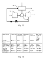
- FIG 9 illustrates the control system 161 used to control bypass damper valve 137, drive damper valve 146 and secondary damper valve 149.
- Control system 161 receives readings from flow sensor 139, drive system sensor 147 and secondary sensor 150.
- the control system 161 may be a conventional General Electric SpeedtronicTM Mark VI Gas Turbine Control System.
- the SpeedTronic controller monitors various sensors and other instruments associated with a gas turbine. In addition to controlling certain turbine functions, such as fuel flow rate, the SpeedTronic controller generates data from its turbine sensors and presents that data for display to the turbine operator. The data may be displayed using software that generates data charts and other data presentations, such as the General Electric CimplicityTM HMI software product.
- the SpeedtronicTM control system is a computer system that includes microprocessors that execute programs to control the operation of the gas turbine using sensor inputs and instructions from human operators.
- the control system includes logic units, such as sample and hold, summation and difference units, which may be implemented in software or by hardwire logic circuits.
- the commands generated by the control system processors cause actuators on the gas turbine to, for example, adjust the fuel control system that supplies fuel to the combustion chamber, set the inlet guide vanes to the compressor, and adjust other control settings on the gas turbine.
- the control system 161 includes computer processors and data storage that convert the sensor readings to data using various algorithms executed by the processors.
- the data generated by the algorithms are indicative of various operating conditions of the gas turbine.
- the data may be presented on operator displays 163, such as a computer work station, that is electronically coupled to the operator display.
- the display and or controller may generate data displays and data printouts using software, such as the General Electric CimplicityTM data monitoring and control software application.
- Illustrated in Figure 10 is an embodiment where the prime mover 131 is a gas turbine 171.
- Gas turbine 171 provides certain benefits over another type of prime mover 131. These benefit include greater reliability, particularly in applications where sustained high power output is required and high efficiencies at high loads.
- the drawback to the use of a gas turbine 171 as a prime mover 131 include lower efficiency that reciprocating engines at part loads and higher costs.
- the gas turbine 171 receives supercharged and cooled air through drive bypass 145 and its exhaust may be conveyed to the HRSG 123 though drive exhaust conduit 155 for best cycle efficiency and flexibility. This results in excellent full-load and part-load efficiency and operational flexibility.
- the forced draft fan 130 driven by gas turbine 171 eliminates output degradation over time by trading efficiency to make up for output degradation.
- the forced draft fan 130 driven by gas turbine 171 also provides the operator with the ability to expand the power generation to steam production ratio envelope. Furthermore, the forced draft fan 130 driven by gas turbine 171, increases net power production and improves efficiency of gas turbine subsystem 113 combined cycle system 111. By expanding the operating envelope, the operator may reduce the negative capital & operating cost impact of needing to add a unit at a multi-unit power block where there is a partial output shortfall.
- the use of a gas turbine 171 has the disadvantages of high capital and maintenance costs. Gas turbine 171 provides a subsystem of medium complexity with high cycle efficiency and very high peak output at fixed supercharger boost.
- FIG 11 illustrates another embodiment where an aeroderivative gas turbine 173 is used as the prime mover 131.
- An aeroderivative gas turbine 173 is a gas turbine derived from an aviation turbine. The decision to use aeroderivative gas turbine 173 is mainly based on economical and operational advantages. They are relatively light weight and offer high performance and efficiency. Aeroderivative gas turbine 173 permits efficient control of torque together with potential for integrated control. Common economic/operational advantages and benefits of the aeroderivative gas turbine 173 compared to conventional heavy frame gas turbine drivers are a 10 to 15 percent improvement in efficiency.
- An aeroderivative gas turbine 173 provides smooth, controlled start. Aeroderivative gas turbine 173 has higher availability and operational reliability and its wide load range permits economically optimized power control.
- An aeroderivative gas turbine 173 also provides an advantage over conventional heavy frame gas turbine drivers due to its ability to be shut down, ramp up rapidly and handle load changes more efficiently.
- An aeroderivative gas turbine 173 provides high cycle efficiency and very high peak output at a fixed supercharger boost.
- the advantages of the aeroderivative gas turbine 173 for this application must be balanced against some disadvantages, including high capital costs and very high maintenance costs.
- FIG 12 illustrates another embodiment where a steam turbine 175 is used as the prime mover 131.
- a steam turbine is a device that extracts thermal energy from pressurized steam and uses it to do mechanical work on a rotating output shaft.
- the use of a steam turbine 175 provides the advantage of being able to use wide range of fuels to drive the steam turbine 175.
- the steam turbine In comparison to the other prime movers, the steam turbine has a medium capital cost, maintenance cost, cycle efficiency, and peak output at fixed supercharger boost.
- Steam turbine 175 also has a high subsystem complexity. However, steam turbine 175 has the disadvantage of requiring boiler and other equipment and a higher price-to-performance ratio.
- a steam turbine 175 has a slow load change behavior, which means once running the steam turbine 175 cannot be stopped quickly. A specific amount of time is needed to slow down its revolutions.
- a steam turbine 175 also has poor part load performance.
- Figure 13 illustrates another embodiment where an induction motor 177 is used as the prime mover 131.
- An induction motor 177 is a type of AC motor where power is supplied to the rotor by means of electromagnetic induction, rather than a commutator or slip rings as in other types of motor.
- Induction motor 177 has the advantage of being rugged, easy to operate, and having low capital and maintenance costs.
- Induction motor 177 also has the advantage of providing a subsystem of low complexity.
- Another advantage of an induction motor 177 is the ability to regulate the torque output and modulate the energy output of the induction motor 177.
- Induction motor 177 has the disadvantage of having a low starting torque, low cycle efficiency and low peak output at fixed supercharger boost. Additionally, speed of the induction motor 177 decreases as the load increases.
- FIG 14 illustrates another embodiment where reciprocating engine 179 is used as the prime mover 131.
- a reciprocating engine 179 also often known as a piston engine, is a heat engine such as a diesel engine that uses one or more reciprocating pistons to convert pressure into a rotating motion.
- Use of a reciprocating engine 179 to drive the forced draft fan 130 has the advantage of providing high efficiencies at part load operation and high cycle efficiencies. Peak output at fixed supercharger boost is very high with a reciprocating engine 179, Additionally a reciprocating engine 179 has short start-up times to full loads.
- a reciprocating engine has average capital costs and maintenance cost. The complexity of the subsystem is average when compared to other prime movers.
- VFD 181 variable frequency drive
- VFD 181 is a drive that controls the rotational speed of an electric motor by controlling the frequency of the electrical power supplied to the motor.
- VFD 181 provides a number of advantages, including low subsystem complexity and low maintenance costs as well as energy savings from operating at lower than nominal speeds.
- VFD 181 has average capital costs when compared with other prime movers and provides average cycle efficiency.
- Another advantage is that VFD 181 may be gradually ramped up to speed lessening the stress on the equipment.
- a disadvantage is lower than average peak output at a fixed supercharger boost.
- Figure 17 is a flow chart of a method 211 for operating a combined cycle system 111.
- step 213 the operator determines a first operating state.
- step 215 the operator determines a desired operating state.
- desired operating states may be an improved ramp up performance of a combined cycle system 111.
- Another desired operating state may be an expanded power generation to steam production ratio for a combined cycle system 111.
- Yet another desired operating state may be an operating state where output degradation over time is reduced by sacrificing efficiency of the of the combined cycle system 111.
- Another desired operating state may be increased net power production and improvement to the efficiency of the combined cycle system 111.
- step 217 the method 211 determines a first mass flow quantity of air to be provided to a gas turbine compressor to achieve the desired operating state.
- step 219 the method 211 determines a second mass flow quantity of air to be provided to a heat recovery steam generator to achieve the desired operating state.
- step 221 the method 211 determines a third mass flow quantity of air to be provided to a prime mover to achieve the desired operating state.
- step 223 the method 211 drives a forced draft fan with a prime mover to provide an air flow
- step 225 the method 211 divides the air flow into a first mass flow portion associated with the first mass flow quantity, a second mass flow portion associated with the second mass flow quantity, and a third mass flow portion associated with the third mass flow quantity.
- step 227 the method 211 conveys the first mass flow portion into the compressor
- step 229 the method 211 conveys the second mass flow portion to the heat recovery steam generator.
- step 231 the method 211 conveys the third mass flow portion to the prime mover.
Landscapes
- Engineering & Computer Science (AREA)
- Chemical & Material Sciences (AREA)
- Combustion & Propulsion (AREA)
- General Engineering & Computer Science (AREA)
- Mechanical Engineering (AREA)
- Physics & Mathematics (AREA)
- Sustainable Energy (AREA)
- Thermal Sciences (AREA)
- Sustainable Development (AREA)
- Life Sciences & Earth Sciences (AREA)
- Fluid Mechanics (AREA)
- Engine Equipment That Uses Special Cycles (AREA)
- Control Of Turbines (AREA)
Applications Claiming Priority (1)
| Application Number | Priority Date | Filing Date | Title |
|---|---|---|---|
| US13/721,870 US9140184B2 (en) | 2012-05-31 | 2012-12-20 | Supercharged combined cycle system with air flow bypass to HRSG and fan |
Publications (2)
| Publication Number | Publication Date |
|---|---|
| EP2746554A2 true EP2746554A2 (de) | 2014-06-25 |
| EP2746554A3 EP2746554A3 (de) | 2017-12-06 |
Family
ID=49916846
Family Applications (1)
| Application Number | Title | Priority Date | Filing Date |
|---|---|---|---|
| EP13198226.6A Withdrawn EP2746554A3 (de) | 2012-12-20 | 2013-12-18 | Aufgeladenes GuD- Kraftwerk mit Luft-Bypass zum Abhitzedampferzeuger |
Country Status (3)
| Country | Link |
|---|---|
| EP (1) | EP2746554A3 (de) |
| JP (1) | JP6291245B2 (de) |
| CN (1) | CN203925754U (de) |
Families Citing this family (2)
| Publication number | Priority date | Publication date | Assignee | Title |
|---|---|---|---|---|
| US9850818B2 (en) * | 2015-06-29 | 2017-12-26 | General Electric Company | Power generation system exhaust cooling |
| CN106330055A (zh) * | 2016-09-12 | 2017-01-11 | 新疆广汇中化能源技术开发有限公司 | 转式辐射床系统 |
Family Cites Families (9)
| Publication number | Priority date | Publication date | Assignee | Title |
|---|---|---|---|---|
| US3568016A (en) * | 1968-10-14 | 1971-03-02 | Bucyrus Erie Co | Variable speed motor ventilation system |
| EP1206634A4 (de) * | 1999-06-10 | 2005-10-12 | Enhanced Turbine Output Holdin | Aufladesystem für gasturbinen |
| US6644011B2 (en) * | 2000-03-24 | 2003-11-11 | Cheng Power Systems, Inc. | Advanced Cheng Combined Cycle |
| US6430915B1 (en) * | 2000-08-31 | 2002-08-13 | Siemens Westinghouse Power Corporation | Flow balanced gas turbine power plant |
| US6530224B1 (en) * | 2001-03-28 | 2003-03-11 | General Electric Company | Gas turbine compressor inlet pressurization system and method for power augmentation |
| US20030182944A1 (en) * | 2002-04-02 | 2003-10-02 | Hoffman John S. | Highly supercharged gas-turbine generating system |
| JP5415276B2 (ja) * | 2006-12-01 | 2014-02-12 | アルストム テクノロジー リミテッド | ガスタービンを運転する方法 |
| US20090193809A1 (en) * | 2008-02-04 | 2009-08-06 | Mark Stewart Schroder | Method and system to facilitate combined cycle working fluid modification and combustion thereof |
| IL199803A (en) * | 2009-07-12 | 2012-07-31 | Lv Technologies Ltd | Method and system for enhancing engine performance |
-
2013
- 2013-12-17 JP JP2013259695A patent/JP6291245B2/ja not_active Expired - Fee Related
- 2013-12-18 EP EP13198226.6A patent/EP2746554A3/de not_active Withdrawn
- 2013-12-20 CN CN201320851076.6U patent/CN203925754U/zh not_active Expired - Fee Related
Non-Patent Citations (1)
| Title |
|---|
| None |
Also Published As
| Publication number | Publication date |
|---|---|
| JP6291245B2 (ja) | 2018-03-14 |
| CN203925754U (zh) | 2014-11-05 |
| EP2746554A3 (de) | 2017-12-06 |
| JP2014122623A (ja) | 2014-07-03 |
Similar Documents
| Publication | Publication Date | Title |
|---|---|---|
| US9140184B2 (en) | Supercharged combined cycle system with air flow bypass to HRSG and fan | |
| US9567913B2 (en) | Systems and methods to extend gas turbine hot gas path parts with supercharged air flow bypass | |
| US20130318965A1 (en) | Supercharged Combined Cycle System With Air Flow Bypass To HRSG And Hydraulically Coupled Fan | |
| EP2669487A2 (de) | Aufgeladenes kombiniertes Kreislaufsystem mit Luftstrom-Bypass | |
| RU2718735C2 (ru) | Комплексный блок генерации энергии и сжатия и соответствующий способ | |
| US9388737B2 (en) | Aero boost—gas turbine energy supplementing systems and efficient inlet cooling and heating, and methods of making and using the same | |
| JP4923014B2 (ja) | 2軸式ガスタービン | |
| US10107199B2 (en) | Aero boost—gas turbine energy supplementing systems and efficient inlet cooling and heating, and methods of making and using the same | |
| EP2669491A2 (de) | Gasturbinenkompressoreinlass-Druckbeaufschlagung mit einem Drehmomentwandlersystem | |
| US9822705B2 (en) | Power augmentation system for a gas turbine | |
| CA2902461A1 (en) | Hybrid turbo electric aero-propulsion system control | |
| RU2626038C1 (ru) | Приводная газотурбинная установка газоперекачивающего агрегата с утилизационной турбоустановкой автономного электроснабжения | |
| US20170096936A1 (en) | Gas turbine assembly | |
| WO2018106991A1 (en) | Air logic control for auxiliary air injection system | |
| EP2746554A2 (de) | Aufgeladenes GuD- Kraftwerk mit Luft-Bypass zum Abhitzedampferzeuger | |
| CN105545770A (zh) | 大型静叶可调轴流式风机汽电交替驱动和联合驱动的轴系 | |
| CN205331014U (zh) | 大型静叶可调轴流式风机汽电交替驱动和联合驱动的轴系 | |
| RU2557834C2 (ru) | Газотурбодетандерная энергетическая установка газораспределительной станции | |
| RU2740388C1 (ru) | Способ работы компрессорной станции магистральных газопроводов с газотурбинными и электроприводными газоперекачивающими агрегатами и газотурбодетандерной энергетической установкой | |
| JP2011027047A (ja) | 2軸式ガスタービン及びその制御装置 | |
| US20160245112A1 (en) | Method for operating a gas turbine arrangement | |
| GB2395753A (en) | Fuel compressor system for a gas turbine | |
| CN204827550U (zh) | 直流发电机调速的背压式小汽机驱动风机系统及配置该系统的发电机组 | |
| AU2016303372A1 (en) | Engine | |
| JPH06101502A (ja) | ガスタービンシステム |
Legal Events
| Date | Code | Title | Description |
|---|---|---|---|
| PUAI | Public reference made under article 153(3) epc to a published international application that has entered the european phase |
Free format text: ORIGINAL CODE: 0009012 |
|
| 17P | Request for examination filed |
Effective date: 20131218 |
|
| AK | Designated contracting states |
Kind code of ref document: A2 Designated state(s): AL AT BE BG CH CY CZ DE DK EE ES FI FR GB GR HR HU IE IS IT LI LT LU LV MC MK MT NL NO PL PT RO RS SE SI SK SM TR |
|
| AX | Request for extension of the european patent |
Extension state: BA ME |
|
| PUAL | Search report despatched |
Free format text: ORIGINAL CODE: 0009013 |
|
| AK | Designated contracting states |
Kind code of ref document: A3 Designated state(s): AL AT BE BG CH CY CZ DE DK EE ES FI FR GB GR HR HU IE IS IT LI LT LU LV MC MK MT NL NO PL PT RO RS SE SI SK SM TR |
|
| AX | Request for extension of the european patent |
Extension state: BA ME |
|
| RIC1 | Information provided on ipc code assigned before grant |
Ipc: F01K 23/10 20060101ALI20171102BHEP Ipc: F02C 6/18 20060101AFI20171102BHEP Ipc: F02C 9/18 20060101ALI20171102BHEP Ipc: F01D 17/00 20060101ALI20171102BHEP |
|
| R17P | Request for examination filed (corrected) |
Effective date: 20180606 |
|
| RBV | Designated contracting states (corrected) |
Designated state(s): AL AT BE BG CH CY CZ DE DK EE ES FI FR GB GR HR HU IE IS IT LI LT LU LV MC MK MT NL NO PL PT RO RS SE SI SK SM TR |
|
| GRAP | Despatch of communication of intention to grant a patent |
Free format text: ORIGINAL CODE: EPIDOSNIGR1 |
|
| INTG | Intention to grant announced |
Effective date: 20190404 |
|
| STAA | Information on the status of an ep patent application or granted ep patent |
Free format text: STATUS: THE APPLICATION IS DEEMED TO BE WITHDRAWN |
|
| 18D | Application deemed to be withdrawn |
Effective date: 20190817 |