EP2669512A1 - Erdungsanordnung - Google Patents
Erdungsanordnung Download PDFInfo
- Publication number
- EP2669512A1 EP2669512A1 EP20120170517 EP12170517A EP2669512A1 EP 2669512 A1 EP2669512 A1 EP 2669512A1 EP 20120170517 EP20120170517 EP 20120170517 EP 12170517 A EP12170517 A EP 12170517A EP 2669512 A1 EP2669512 A1 EP 2669512A1
- Authority
- EP
- European Patent Office
- Prior art keywords
- grounding
- rotor
- brush
- generator
- stator
- Prior art date
- Legal status (The legal status is an assumption and is not a legal conclusion. Google has not performed a legal analysis and makes no representation as to the accuracy of the status listed.)
- Granted
Links
- 238000012423 maintenance Methods 0.000 claims abstract description 13
- 238000000034 method Methods 0.000 claims abstract description 11
- 230000000295 complement effect Effects 0.000 claims description 6
- 238000002955 isolation Methods 0.000 claims description 5
- OKTJSMMVPCPJKN-UHFFFAOYSA-N Carbon Chemical compound [C] OKTJSMMVPCPJKN-UHFFFAOYSA-N 0.000 description 48
- 229910052799 carbon Inorganic materials 0.000 description 45
- 238000010586 diagram Methods 0.000 description 9
- 230000008901 benefit Effects 0.000 description 4
- 238000013461 design Methods 0.000 description 4
- 230000000694 effects Effects 0.000 description 4
- 229910000831 Steel Inorganic materials 0.000 description 3
- 238000011161 development Methods 0.000 description 3
- 230000007246 mechanism Effects 0.000 description 3
- 239000010959 steel Substances 0.000 description 3
- RYGMFSIKBFXOCR-UHFFFAOYSA-N Copper Chemical compound [Cu] RYGMFSIKBFXOCR-UHFFFAOYSA-N 0.000 description 2
- 230000009471 action Effects 0.000 description 2
- 239000004020 conductor Substances 0.000 description 2
- 229910052802 copper Inorganic materials 0.000 description 2
- 239000010949 copper Substances 0.000 description 2
- 230000002349 favourable effect Effects 0.000 description 2
- 229910002804 graphite Inorganic materials 0.000 description 2
- 239000010439 graphite Substances 0.000 description 2
- 239000000463 material Substances 0.000 description 2
- 239000007787 solid Substances 0.000 description 2
- 229910001369 Brass Inorganic materials 0.000 description 1
- 239000000956 alloy Substances 0.000 description 1
- 229910045601 alloy Inorganic materials 0.000 description 1
- 238000013459 approach Methods 0.000 description 1
- 239000010951 brass Substances 0.000 description 1
- 238000012937 correction Methods 0.000 description 1
- 230000008878 coupling Effects 0.000 description 1
- 238000010168 coupling process Methods 0.000 description 1
- 238000005859 coupling reaction Methods 0.000 description 1
- 230000007812 deficiency Effects 0.000 description 1
- 230000001419 dependent effect Effects 0.000 description 1
- 238000007599 discharging Methods 0.000 description 1
- 238000009826 distribution Methods 0.000 description 1
- 239000011152 fibreglass Substances 0.000 description 1
- 239000011810 insulating material Substances 0.000 description 1
- 238000009413 insulation Methods 0.000 description 1
- 238000003754 machining Methods 0.000 description 1
- 238000004519 manufacturing process Methods 0.000 description 1
- 239000002184 metal Substances 0.000 description 1
- 229910052751 metal Inorganic materials 0.000 description 1
- 238000003801 milling Methods 0.000 description 1
- 238000012986 modification Methods 0.000 description 1
- 230000004048 modification Effects 0.000 description 1
- 239000002245 particle Substances 0.000 description 1
- 230000008439 repair process Effects 0.000 description 1
- 238000007789 sealing Methods 0.000 description 1
- 238000004804 winding Methods 0.000 description 1
Images

Classifications
-
- H—ELECTRICITY
- H02—GENERATION; CONVERSION OR DISTRIBUTION OF ELECTRIC POWER
- H02K—DYNAMO-ELECTRIC MACHINES
- H02K11/00—Structural association of dynamo-electric machines with electric components or with devices for shielding, monitoring or protection
- H02K11/40—Structural association with grounding devices
-
- F—MECHANICAL ENGINEERING; LIGHTING; HEATING; WEAPONS; BLASTING
- F03—MACHINES OR ENGINES FOR LIQUIDS; WIND, SPRING, OR WEIGHT MOTORS; PRODUCING MECHANICAL POWER OR A REACTIVE PROPULSIVE THRUST, NOT OTHERWISE PROVIDED FOR
- F03D—WIND MOTORS
- F03D80/00—Details, components or accessories not provided for in groups F03D1/00 - F03D17/00
- F03D80/30—Lightning protection
-
- F—MECHANICAL ENGINEERING; LIGHTING; HEATING; WEAPONS; BLASTING
- F03—MACHINES OR ENGINES FOR LIQUIDS; WIND, SPRING, OR WEIGHT MOTORS; PRODUCING MECHANICAL POWER OR A REACTIVE PROPULSIVE THRUST, NOT OTHERWISE PROVIDED FOR
- F03D—WIND MOTORS
- F03D80/00—Details, components or accessories not provided for in groups F03D1/00 - F03D17/00
- F03D80/70—Bearing or lubricating arrangements
-
- F—MECHANICAL ENGINEERING; LIGHTING; HEATING; WEAPONS; BLASTING
- F05—INDEXING SCHEMES RELATING TO ENGINES OR PUMPS IN VARIOUS SUBCLASSES OF CLASSES F01-F04
- F05B—INDEXING SCHEME RELATING TO WIND, SPRING, WEIGHT, INERTIA OR LIKE MOTORS, TO MACHINES OR ENGINES FOR LIQUIDS COVERED BY SUBCLASSES F03B, F03D AND F03G
- F05B2220/00—Application
- F05B2220/70—Application in combination with
- F05B2220/706—Application in combination with an electrical generator
- F05B2220/7066—Application in combination with an electrical generator via a direct connection, i.e. a gearless transmission
-
- F—MECHANICAL ENGINEERING; LIGHTING; HEATING; WEAPONS; BLASTING
- F05—INDEXING SCHEMES RELATING TO ENGINES OR PUMPS IN VARIOUS SUBCLASSES OF CLASSES F01-F04
- F05B—INDEXING SCHEME RELATING TO WIND, SPRING, WEIGHT, INERTIA OR LIKE MOTORS, TO MACHINES OR ENGINES FOR LIQUIDS COVERED BY SUBCLASSES F03B, F03D AND F03G
- F05B2240/00—Components
- F05B2240/50—Bearings
-
- H—ELECTRICITY
- H02—GENERATION; CONVERSION OR DISTRIBUTION OF ELECTRIC POWER
- H02K—DYNAMO-ELECTRIC MACHINES
- H02K7/00—Arrangements for handling mechanical energy structurally associated with dynamo-electric machines, e.g. structural association with mechanical driving motors or auxiliary dynamo-electric machines
- H02K7/18—Structural association of electric generators with mechanical driving motors, e.g. with turbines
- H02K7/1807—Rotary generators
- H02K7/1823—Rotary generators structurally associated with turbines or similar engines
- H02K7/183—Rotary generators structurally associated with turbines or similar engines wherein the turbine is a wind turbine
- H02K7/1838—Generators mounted in a nacelle or similar structure of a horizontal axis wind turbine
-
- Y—GENERAL TAGGING OF NEW TECHNOLOGICAL DEVELOPMENTS; GENERAL TAGGING OF CROSS-SECTIONAL TECHNOLOGIES SPANNING OVER SEVERAL SECTIONS OF THE IPC; TECHNICAL SUBJECTS COVERED BY FORMER USPC CROSS-REFERENCE ART COLLECTIONS [XRACs] AND DIGESTS
- Y02—TECHNOLOGIES OR APPLICATIONS FOR MITIGATION OR ADAPTATION AGAINST CLIMATE CHANGE
- Y02E—REDUCTION OF GREENHOUSE GAS [GHG] EMISSIONS, RELATED TO ENERGY GENERATION, TRANSMISSION OR DISTRIBUTION
- Y02E10/00—Energy generation through renewable energy sources
- Y02E10/70—Wind energy
- Y02E10/72—Wind turbines with rotation axis in wind direction
Definitions
- the invention describes a grounding arrangement for a direct-drive wind turbine generator; a grounding element for use in such a grounding arrangement; a direct-drive wind turbine generator; and a method of performing maintenance on a grounding arrangement.
- a shaft voltage can build up on the rotating part of the machine.
- the shaft voltages appear to be caused by converter PWM (pulse-width modulation) switching.
- PWM pulse-width modulation
- a current associated with this shaft voltage will seek a path to ground.
- the only path to ground may go through a bearing between the rotor and the stator. Over time, these discharge currents can damage the bearing by causing fretting in raceways and on rollers. Since the bearing must fulfil the very critical function of ensuring a smooth operation of the rotor, it is of paramount importance to protect the bearing from such discharge currents.
- Grounding mechanisms for the bearings of an electrical machine are known, and there are several different approaches, depending on the type of machine.
- High-speed, relatively small machines can use solid metal grounding rings arranged between shaft and bearing casing to provide a current path to electrical ground.
- grounding solution In a wind turbine generator, the choice of grounding solution depends to a large extent on the topology of the wind turbine drive. In many conventional wind turbines, the drive train and generator are separate and are coupled by means of a gearbox. Grounding is not difficult to achieve for such machines, since the rotor is an inner rotor and is coupled to the gear box shaft, so that a path to electrical ground, circumventing any bearing, can easily be found for a voltage that has built up on the rotor.
- the generator and drive train are realised as a single entity, without any gearbox. Instead, the generator is coupled directly to the rotor, usually an outer rotor, of the wind turbine. Due to the large rotor size - in the order of several meters in diameter - and other geometric constraints, it is very difficult to ground the bearing current in such a direct-drive generator. In a medium- to low-speed direct-drive generator, because of the large dimensions involved, it is practically impossible to employ grounding rings. Such a grounding ring cannot be applied to an outer rotor of a direct-drive permanent magnet machine, since there is no shaft-like structure to which it could be connected. Therefore, the use of such grounding rings is limited to high-speed applications with correspondingly small shaft diameters.
- a ring of insulating material is usually arranged about the bearing.
- electrical grade fibre-glass is often used as an insulation layer between the main bearing inner ring and the main shaft.
- the presence of the insulating ring will not prevent any voltage from developing on the rotor. Therefore, if the insulating ring is not perfectly realised or does not have the required electrical grade, a voltage on the rotor may still result in a current succeeding in finding a path through the bearing.
- input and output filters are used to counteract the influence of the PWM switching converter.
- these filters are expensive and therefore add to the overall cost of the generator. Furthermore, such filters cannot always reliably rule out the development of voltages on the rotor.
- the grounding arrangement for a direct-drive generator comprises an outer rotor, a stator, and a bearing arranged between the rotor and the stator; which grounding arrangement comprises a number of grounding elements, and wherein a grounding element comprises a grounding brush arranged to provide a current path from the rotor to electrical ground, which current path bypasses the bearing.
- An advantage of the grounding arrangement according to the invention is that the electrical current can always be safely diverted from the bearing by always offering it a direct path to ground, for example a low-resistance path to a casing of the generator.
- An electrical current will always chose the path of least resistance, so that the likelihood of a current seeking a path through the bearing can safely be ruled out.
- expensive filter arrangements are no longer required to counteract the effects of the switching converter.
- the grounding arrangement according to the invention is therefore favourably economical.
- the grounding element for providing a current path to electrical ground from the rotor of a direct-drive wind turbine generator, comprises a grounding brush comprising a spring-loaded portion and a contact portion for electrically contacting a rotor region; a bracket realised to be mounted to a stationary part of the generator; and a holding element realised to hold the grounding brush in the bracket such that the contact portion is pressed against the rotor region.
- grounding element is that it can be manufactured very economically and will not add significantly to the costs of the generator.
- the co-operation of the bracket and holding element serves to ensure that the grounding brush is always pressed against a surface of the generator to offer a current a safe path to ground.
- the direct-drive generator comprises an outer rotor, a stator, and a bearing arranged between the rotor and the stator, which generator comprises a grounding arrangement according to the invention to provide a current path from the rotor to electrical ground, and wherein the grounding arrangement preferably comprises a number of grounding elements according to the invention.
- An advantage of the direct-drive generator according to the invention is that the bearing can be reliably protected from the negative effects of a current discharge. Therefore, the direct-drive generator according to the invention does not explicitly require an expensive filter arrangement to avoid the build-up of voltages on the rotor. Instead, such voltages may be deliberately allowed to build up, since the grounding arrangement can effectively deal with them. The costs of manufacture and maintenance for the direct-drive generator according to the invention are also favourably reduced.
- the method of performing maintenance on such a grounding arrangement comprises the step of adjusting the position of the grounding brush in a grounding element to increase a pressure between the contact portion of the grounding brush and a corresponding contact region to ensure an uninterrupted current path from the outer rotor to electrical ground that bypasses the bearing.
- This pressure may be referred to in the following simply as the "contact pressure”.
- An advantage of the method according to the invention is that the functionality of a grounding element of the grounding arrangement can be quickly and easily ensured.
- a maintenance procedure can simply involve a correction of the position of a grounding brush. Since a grounding element can be secured at a convenient position on the generator, the grounding element can be quickly accessed and adjusted, as will be made clear in the description and the diagrams.
- the direct-drive generator is the generator of a wind turbine.
- the rotor is an outer rotor arranged about the stator, and the rotor rotates at a relatively low speed, typically in the order of only a few revolutions per minute (rpm).
- the rotor blades are usually very long, and a rotor blade can be 20 - 30 m or more in length.
- the outer rotor may be assumed in the following to comprise a rotor housing in the form of a cylindrical structure, with a plurality of magnets arranged on its interior; a rotor front plate at the drive or hub end of the rotor housing that extends from an outer perimeter of the rotor housing to the main bearing; and a brake plate at the non-drive end that serves to halt the rotation of the rotor housing when necessary.
- the stator may be assumed to comprise a stator main shaft to which the main bearing is connected, and an outer frame to which the stator windings or coils are mounted such that these face the magnets across a narrow air-gap.
- the main bearing of a direct-drive wind turbine is generally located at the hub side, between the rotor and the stator.
- An inner ring of the main bearing is usually bolted about a main shaft of the stator.
- a physical contact between the rotor and the main bearing is usually achieved by a circular front plate that is part of the rotor and that extends from an outer rotor edge inward to the bearing. This will be shown in the diagrams.
- a first set of grounding elements is arranged at the main bearing side, i.e. the hub side of the generator. In this case, a grounding element makes an electrical contact between the rotor front plate and the stator main shaft.
- any rotor shaft voltages that build up can discharge directly in a current path through the front plate, and into the stator main shaft, which can be effectively regarded as electrical ground, since the main shaft usually makes direct electrical contact to a bed-frame, which in turn is either in electrical contact with a tower top flange, or a low-resistance path between the bed-frame and tower top flange can be provided by other means.
- a wind turbine is equipped with a lightning protection system, so that there would be a lightning grounding path from the blades to a tower top flange, and the bearing grounding arrangement according to the invention could avail of this.
- the grounding arrangement according to the invention comprises a second set of grounding elements arranged at the brake side of the generator. With these grounding elements at the opposite end of the rotor to the hub side, the shaft voltage can optimally discharge at the brake side.
- a grounding arrangement using only non-drive-end grounding elements could be used to provide a low-resistance current path to ground, and might be included in the initial wind turbine design. Such a grounding arrangement may be added later, should an initial bearing protection fail, for example if a bearing isolation ring becomes damaged at some stage and cannot provide complete protection for the bearing.
- the grounding arrangement comprises an isolation ring arranged about the bearing.
- the grounding brush used in the grounding element according to the invention can be any off-the-shelf or custom component.
- Off-the-shelf carbon brushes used for contacting the commutation slip rings of an electric motor for, generally comprise a block-like contact portion and a spring-loaded portion used to press the contact portion of the brush against a surface.
- the contact portion can be made of pressed graphite or carbon powder, sometimes with added copper for improved conductivity, and can be manufactured as a solid block, as a braided element, or as a bunch of fibres.
- a brush is simply referred to as a "carbon brush”.
- Such a carbon brush can be used to good effect in a grounding arrangement according to the invention, where it is not used for commutation purposes, but is instead used to divert a current away from the main bearing.
- grounding brush carbon brush
- brush may be used interchangeably.
- the present invention uses the carbon brush to good effect, namely to ground the outer rotor of a permanent-magnet direct-drive generator, which would not otherwise require carbon brushes since commutation is not an issue for such a generator.
- One reason why such brushes would not be used in grounding solutions for generators is that they are highly unsuitable for use in a high-speed permanent-magnet machine.
- the geometry and electrical design of a high speed inner rotor machine such as an electric motor readily lends itself to the used of a grounding ring, and the uses of carbon brushes has been restricted to commutation.
- at high rpm rates typically in the order of hundreds or even thousands of rpm, such brushes would wear down extremely quickly and require frequent servicing.
- the holding element of the grounding element comprises a first cavity realised to accommodate the carbon brush such that the contact portion of the carbon brush protrudes beyond an outer face of the holding element.
- the first cavity is preferably machined to fit snugly about the contact portion, so that the front of the contact portion is always pressed flat against the surface with which it should make contact.
- the contact portion has a square or rectangular cross-section.
- the first cavity is formed to have such a square or rectangular cross-section, at least over a section of its length.
- one end of the first cavity at the outer end of the holding element can be milled to form a square cross-section.
- the length of the milled square cross-section might correspond to one half, one third or any suitable fraction of the length of the contact portion of a carbon brush. Since milling a square or rectangular opening is generally relatively expensive, the square portion of the first cavity can be kept to a reasonable minimum, and any remaining length of the first cavity can be formed as a simple round bore.
- a contact portion with a square or rectangular cross-section is better at maintaining a favourable electrical contact at all times, since the contact portion cannot rotate about its longitudinal axis within the cavity.
- a first cavity with a square portion is preferable.
- a carbon brush with an essentially cylindrical contact portion having a round cross-section could conceivably be used, in which case the entire first cavity could be formed relatively cheaply as a straightforward circular bore.
- the grounding element comprises a feed adjuster for adjusting the position of the carbon brush in the holding element.
- the feed adjuster is preferably realised to increase the contact pressure between the outer face of the contact portion and the surface against which it is pressed.
- the holding element comprises a second cavity realised to accommodate the feed adjuster.
- the feed adjuster can be preferably realised as a screw that can be turned to move it further into the holding element such that it would act to compress the spring portion of the carbon brush.
- the holding element comprises an inner threaded portion realised to complement an outer threaded portion of the feed adjuster.
- the feed adjuster is realised as a grub screw, to allow a compact realisation of the grounding element, and the second cavity is threaded to accommodate such a grub screw.
- a grub screw usually has a hex socket so that it can be tightened or loosened using a corresponding Allen key.
- the length of the second cavity and its inner thread are preferably machined to complement the length of the "surplus" contact portion held in the first cavity, so that as much as possible of the carbon brush can be effectively used, before having to replace it, for example by screwing the feed adjuster further into the second cavity.
- An indication that a carbon brush is worn down to a critical limit might be given when the feed adjuster cannot be moved any further into the second cavity.
- the grounding element comprises a bracket with which the holding element is secured relative to the rotating part of the generator.
- the bracket and holding element could be realised in one piece. This might require very exact machining to ensure that the holding element is at a correct distance from the rotating part.
- the bracket and holding element are realised separately, so that the position of the holding element relative to the rotating part can be adjusted as required.
- the holding element and bracket could be realised such that the holding element is clamped in the bracket, for example.
- the holding element comprises an outer threaded portion realised to complement an inner threaded portion of the bracket, so that the holding element can be screwed into the bracket.
- the threaded realisation allows a very precise adjustment of the distance between the holding element (and therefore also of the carbon brush it contains) and the rotating part of the generator.
- the grounding arrangement can comprise grounding elements mounted at the drive end (the hub side) or the non-drive end (the brake side) of the generator.
- the geometries of the drive end and the non-drive end are very different. Therefore, in a further preferred embodiment of the invention, the bracket is realised for mounting to a stator shaft such that the carbon brush contacts a bearing surface to provide a current path from the rotor through the stator shaft to electrical ground and/or for mounting to a brake disc such that the carbon brush contacts a rotor surface to provide a current path from the rotor through the brake disc to electrical ground.
- the bracket can be realised accordingly.
- the bracket could be three-dimensional, flat, curved; with an L-shape, a straight shape, etc.
- a grounding arrangement can comprise any appropriate number of grounding elements.
- a single grounding element may be sufficient to ensure good contact and a low-resistance path to ground. Care should be taken to replace the worn brush in good time.
- a grounding arrangement comprises two or more brushes.
- a first "three-brush" grounding arrangement could comprise three grounding elements arranged between the stator shaft and the rotor front plate.
- a second grounding arrangement for example at the non-drive end, might be a "two-brush" grounding arrangement with a pair of grounding elements arranged between the brake plate and the rotor housing.
- the material(s) of which the holding element and/or feed adjuster and/or bracket are made comprise good conductive materials such as steel, brass, copper, an alloy of two or more materials, etc.
- an appropriate component preferably comprises a number of access openings arranged to provide access to a bracket of a grounding element.
- an access opening in the stator front plate can allow quick and easy access to the feed adjuster of the grounding element, so that a contact pressure can be adjusted, or a worn-down brush can be easily replaced by a new one.
- an access opening may be required, for example for a wind turbine with a high IP (International Protection) rating.
- Such access openings may be realised with sealing covers, so that, when not in use, an air-tight seal is made, to prevent moisture or air-borne particles from entering.
- a cover may not be mandatory, so that the grounding elements can be accessed very easily.
- a maintenance step for ensuring good contact to the carbon brushes, preferably comprises the steps of removing a feed adjuster of a grounding element and then removing the carbon brush from that grounding element. Then, a replacement carbon brush can be inserted, and the feed adjuster can be replaced and tightened such that a pressure is established between the contact portion of the carbon brush and a corresponding contact region.
- the carbon brushes of a grounding arrangement may be installed such that, initially, they have different lengths. They may be assumed to wear down equally over time. By ensuring that the carbon brushes of the grounding elements have different lengths, even if one or two carbon brushes of a multi-brush grounding arrangement should wear down, at least one brush remains to fulfil the function of providing a current path to ground that bypasses the bearing until a maintenance step can be carried out.
- Such an arrangement, with varying initial brush lengths can be advantageous also in the case when the rotor has an inherent imbalance or eccentricity that results in an uneven loading of the brushes. The length of a brush that is subject to more wear could initially be longer than the other brushes, to counteract the uneven loading by the rotor.
- the time taken to wear down a carbon brush can be reliably estimated, since information pertaining to the number of revolutions made by the rotor housing, the force acting to press the contact portion against a rotating part, the original length of the contact portion, etc., can be determined. Using this information, the expected lifetime of a carbon brush (i.e. the useful lifetime of the contact portion) can be computed.
- a maintenance procedure can therefore be planned in advance, for example to coincide with other maintenance work on other components or units of the generator.
- the worn-down brush and the other only partially worn-down brushes may all be replaced by brushes of different lengths, as mentioned above, or by new brushes of equal length.
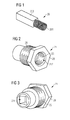
- Fig. 1 shows a carbon brush 20 for use in a grounding element according to the invention.
- the carbon brush 20 has a spring-loaded portion 201 and a contact portion 202 for electrically contacting a rotor region.
- the contact portion 202 usually made mostly of graphite, may wear down over time on account of the friction between the front face of the contact portion 202 and the part against which it presses.
- the spring-loaded portion 201 usually made of steel and partially embedded in the contact portion 202, has a spring constant large enough to ensure that the contact portion 202 is pressed with sufficient force against the relevant part to be contacted.
- the diameter of the spring portion 201 does not exceed the width of the contact portion 202.
- Figs. 2, 3 , and 4 show various views of a holding element 21 according to an embodiment of the invention, for holding the carbon brush 20 of Fig. 1 .
- the entire holding element 21 can be made in one piece of an electrically conductive material such as industrial grade steel.
- the holding element 21 comprises a first cavity 211 that is shaped to accommodate the carbon brush 20, and a second cavity 212 shaped to accommodate a feed adjuster 24.
- the first cavity 211 in this embodiment has a square cross-section, over its entire length, into which both the "square" contact portion 202 and the "round” spring portion 201 fit.
- the width of the first cavity 211 is just slightly wider than the width of the contact portion 202 and the diameter of the spring portion 201.
- the exterior of the holding element 21 is realised to complement a bracket, and comprises an outer thread 26 that matches an inner thread of a bracket, as will be explained with the aid of Fig. 5 below.
- the holding element 21 also comprises a hex head 28 for tightening the holding element 21 in the bracket with a suitable tool such as a hex wrench.
- the holding element 21 has an inner thread 25 to match that of a feed adjuster 24 for adjusting the position of the carbon brush 20, as shown in Fig. 4 .
- the first cavity 211 could have a "square" cavity at its outer end to provide a snug fit for the contact portion 202 of the carbon brush, and a "round” cavity at the other end to contain the spring portion, formed as a counter-bored circular opening that circumscribes the "square" cavity.
- This counter-bored circular cavity can be formed as an extension of the second cavity 212 of the holding element 21.
- the first cavity 211 and second cavity 212 are realised so that a carbon brush can be inserted into the holding element from the "front", i.e. through the second cavity 212.
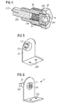
- Fig. 4 shows a cross-section through the holding element 21 containing a carbon brush 20, and a feed adjuster 24, in this case a grub screw 24.
- the carbon brush 20 fits snugly in the first cavity 211, while allowing the contact portion 202 to move in the direction shown, and the spring-loaded portion 201 is also free to extend.
- the inner thread 25 of the second cavity 212 is a right-hand thread
- a force will be applied to the spring-loaded portion 201 when the feed adjuster 24 is turned clockwise.
- the spring portion 201 will compel the contact portion 202 to move "outwards" in the direction shown along the first cavity 201 to extend beyond an outer face of the holding element 21.
- Fig. 5 shows a first embodiment of a bracket 23 realised to accommodate the holding element 2.
- the bracket 23 comprises a three-dimensional L-shaped element with a number of threaded mounting bushings 230 by means of which the bracket 23 can be secured to a component such as a stator shaft.
- the bracket 23 also comprises a holder bushing 231 with an inner thread 232 to match the outer thread 26 of a holding element 21.
- Fig. 6 shows a holding element 21 mounted in a bracket 23.
- the diagram also shows how the feed adjuster 24 can easily be accessed from the front of the bracket 23, while the contact portion 202 of the carbon brush 20 is seen to protrude from beyond the end of the holding element 21.
- Fig. 7 shows a cross-section of a part of a generator 3 and a grounding element 2.
- a circular rotor housing 30 is arranged about a circular main bearing 32 by means of a rotor front plate 301.
- a grounding element 2 is mounted between the stator shaft 31 and the rotor front plate 301 such that the contact portion 202 of a carbon brush is pressed against a surface of the rotor front plate 301. Since the grounding element 2 is entirely conductive, any voltage V SHAFT building up on the rotor housing 30 can safely discharge as a current travelling through the rotor front plate 301, grounding element 2, and stator shaft 31 through the path P SS to ground.
- the contact portion 202 since the contact portion 202 is actively pressed by the spring portion 201 onto the rotor front plate 301, the contact portion 202 will wear down over time on account of friction between it and the rotor front plate 301.
- the feed adjuster can easily be accessed through an access opening 310 in a stator front plate 311, as shown. A technician can simply tighten the grub screw if the remaining contact portion is long enough.
- the technician can simply remove the grub screw, remove the worn carbon brush, insert a new carbon brush, and replace the grub screw, tightening it sufficiently to ensure a good electrical contact to the rotor front plate 301 again.
- Fig. 7 also shows an additional possible location for a grounding element 2 to contact the rotor hub 302.
- the grounding element 2 is mounted to an anti-ovalization ring 34 that in turn is mounted to the inner race of the main bearing 32. Any shaft voltages V SHAFT that build up on the rotor hub 302 can safely be discharged through the grounding element 2 along the path P OV shown.
- This grounding element 2 can be accessed relatively easily too, since a passage through the cylindrical stator shaft 31 is usually given between the nacelle interior and the hub interior in a direct-drive wind turbine.
- a safe path for any shaft current is afforded either by a path P SS through the stator shaft 31 to ground GND, or by the path P OV through the anti-ovalization ring 34 to ground GND.
- These low-resistance paths P SS , P OV ensure that a current discharge would not seek the path P X through the bearing 32, as indicated in Fig. 8 , which shows a prior art grounding arrangement for a direct-drive wind turbine generator, comprising an isolation ring 4 between the bearing 32 and the rotating parts 301, 302. Any deficiency in the isolation ring 4 can be sufficient to allow a current to discharge through a path P X through the bearing 32, thereby damaging the bearing 32 and resulting in serious damage and costly repairs.
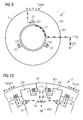
- Fig. 9 is a very simplified cross-section through a generator 3 according to the invention.
- the diagram shows a grounding arrangement 1 comprising three grounding elements 2 arranged more or less equidistantly about the stator shaft 31.
- any shaft voltages V SHAFT that build up can safely discharge as current along the current paths P SS to electrical ground GND, through the rotor front plate 301, the grounding elements 2 and the stator shaft 31.
- the diagram only shows the current path through one exemplary grounding element 2, but it should be understood that the shaft voltage V SHAFT can be distributed about the entire rotor housing 303, and can discharge through each of the three grounding elements 2 and through the stator shaft 31 to ground GND.
- Fig. 10 is a schematic representation of part of a generator 3 according to the invention, as seen from the brake side.
- the diagram shows a brake arrangement with brake shoes 330 and a rotor lock 331 on a stationary brake plate 33, which in turn is mounted to the stator shaft (not shown).
- a flat right-angled bracket 23' for a grounding element 2 is connected to the brake plate 33, so that the grounding element 2 it contains can be pressed against a corresponding surface of the rotor housing 303 as this rotates.
- Another, straight bracket 23" can be secured to the rotor lock 331 so that the grounding element 2 it contains can be pressed against the rotor housing 303 as this rotates.
- any shaft voltages V SHAFT that build up can safely discharge through brake plate current paths P EP to electrical ground GND.
- the braking arrangement can comprise two or three such brake plates 33 arranged about the rotor housing 303 at the nacelle end of the generator 3, and the grounding arrangement 1 can comprise a corresponding number of grounding elements 2.
- grounding arrangement according to the invention could be used in any applications using a direct-drive outer rotor permanent-magnet machine with a single bearing arrangement. Apart from its use in a wind turbine, the grounding arrangement could be used in an application such as large power drives.
Landscapes
- Engineering & Computer Science (AREA)
- Life Sciences & Earth Sciences (AREA)
- Sustainable Development (AREA)
- Sustainable Energy (AREA)
- Chemical & Material Sciences (AREA)
- Combustion & Propulsion (AREA)
- Mechanical Engineering (AREA)
- General Engineering & Computer Science (AREA)
- Power Engineering (AREA)
- Motor Or Generator Frames (AREA)
- Wind Motors (AREA)
- Connection Of Motors, Electrical Generators, Mechanical Devices, And The Like (AREA)
Priority Applications (2)
| Application Number | Priority Date | Filing Date | Title |
|---|---|---|---|
| DK12170517.2T DK2669512T3 (en) | 2012-06-01 | 2012-06-01 | grounding device |
| EP12170517.2A EP2669512B1 (de) | 2012-06-01 | 2012-06-01 | Erdungsanordnung |
Applications Claiming Priority (1)
| Application Number | Priority Date | Filing Date | Title |
|---|---|---|---|
| EP12170517.2A EP2669512B1 (de) | 2012-06-01 | 2012-06-01 | Erdungsanordnung |
Publications (2)
| Publication Number | Publication Date |
|---|---|
| EP2669512A1 true EP2669512A1 (de) | 2013-12-04 |
| EP2669512B1 EP2669512B1 (de) | 2015-09-16 |
Family
ID=46229264
Family Applications (1)
| Application Number | Title | Priority Date | Filing Date |
|---|---|---|---|
| EP12170517.2A Not-in-force EP2669512B1 (de) | 2012-06-01 | 2012-06-01 | Erdungsanordnung |
Country Status (2)
| Country | Link |
|---|---|
| EP (1) | EP2669512B1 (de) |
| DK (1) | DK2669512T3 (de) |
Cited By (2)
| Publication number | Priority date | Publication date | Assignee | Title |
|---|---|---|---|---|
| EP3972095A1 (de) * | 2020-09-18 | 2022-03-23 | Siemens Aktiengesellschaft | Spaltrohr einer dynamoelektrischen maschine |
| CN117189515A (zh) * | 2022-05-30 | 2023-12-08 | 北京金风科创风电设备有限公司 | 风力发电机组 |
Families Citing this family (2)
| Publication number | Priority date | Publication date | Assignee | Title |
|---|---|---|---|---|
| US11149795B2 (en) | 2019-03-01 | 2021-10-19 | Pratt & Whitney Canada Corp. | Turbine engine bearing used as a static electricity leak path |
| EP4210203A1 (de) | 2022-01-08 | 2023-07-12 | General Electric Renovables España S.L. | Elektrische maschinen und verfahren zur verminderung von lagerströmen |
Citations (5)
| Publication number | Priority date | Publication date | Assignee | Title |
|---|---|---|---|---|
| US5804903A (en) * | 1993-10-22 | 1998-09-08 | Fisher; Rodney R. | Motor shaft discharge device |
| US5988996A (en) * | 1997-11-05 | 1999-11-23 | Baker Hughes Incorporated | Electrical shaft grounding brush assembly and holder for a submersible pump motor |
| US6249058B1 (en) * | 1999-12-03 | 2001-06-19 | Monte L. Rea | Wind driven generator having counter-rotating armature and rotor |
| US20030086630A1 (en) * | 2001-11-06 | 2003-05-08 | Illinois Tool Works, Inc. | Method and system for reducing bearing fluting in electromechanical machine |
| DE102009017531A1 (de) * | 2009-04-17 | 2010-10-21 | Avantis Ltd. | Bremssystem eines Generators einer Windenergieanlage |
-
2012
- 2012-06-01 EP EP12170517.2A patent/EP2669512B1/de not_active Not-in-force
- 2012-06-01 DK DK12170517.2T patent/DK2669512T3/en active
Patent Citations (5)
| Publication number | Priority date | Publication date | Assignee | Title |
|---|---|---|---|---|
| US5804903A (en) * | 1993-10-22 | 1998-09-08 | Fisher; Rodney R. | Motor shaft discharge device |
| US5988996A (en) * | 1997-11-05 | 1999-11-23 | Baker Hughes Incorporated | Electrical shaft grounding brush assembly and holder for a submersible pump motor |
| US6249058B1 (en) * | 1999-12-03 | 2001-06-19 | Monte L. Rea | Wind driven generator having counter-rotating armature and rotor |
| US20030086630A1 (en) * | 2001-11-06 | 2003-05-08 | Illinois Tool Works, Inc. | Method and system for reducing bearing fluting in electromechanical machine |
| DE102009017531A1 (de) * | 2009-04-17 | 2010-10-21 | Avantis Ltd. | Bremssystem eines Generators einer Windenergieanlage |
Cited By (4)
| Publication number | Priority date | Publication date | Assignee | Title |
|---|---|---|---|---|
| EP3972095A1 (de) * | 2020-09-18 | 2022-03-23 | Siemens Aktiengesellschaft | Spaltrohr einer dynamoelektrischen maschine |
| WO2022058171A1 (de) * | 2020-09-18 | 2022-03-24 | Flender Gmbh | Dynamoelektrische rotatorische maschine mit einem spaltrohr |
| US12374968B2 (en) | 2020-09-18 | 2025-07-29 | Flender Gmbh | Dynamoelectric rotary machine with a can |
| CN117189515A (zh) * | 2022-05-30 | 2023-12-08 | 北京金风科创风电设备有限公司 | 风力发电机组 |
Also Published As
| Publication number | Publication date |
|---|---|
| DK2669512T3 (en) | 2016-01-04 |
| EP2669512B1 (de) | 2015-09-16 |
Similar Documents
| Publication | Publication Date | Title |
|---|---|---|
| US5804903A (en) | Motor shaft discharge device | |
| US7808149B2 (en) | Generator/electric motor, in particular for wind power plants, cable controlled plants or for hydraulic plants | |
| US5661356A (en) | Motor shaft discharge device | |
| EP2669512B1 (de) | Erdungsanordnung | |
| US9379583B2 (en) | Magnet assembly | |
| US9859672B2 (en) | Electric machine and connecting unit for an electric machine | |
| US20120091724A1 (en) | Braking system of a generator of a wind turbine | |
| EP2187506A1 (de) | Windenergieturbine zur Herstellung elektrischer Energie | |
| CN109314445A (zh) | 电动机转子放电保护 | |
| KR20220136837A (ko) | 통전의 보조 베어링을 장착한 모터 및 발전기의 축전류 방전 장치 | |
| WO2016094972A1 (pt) | Sistema de aterramento de mancais de máquinas elétricas girantes e máquina elétrica correspondente | |
| JP6121980B2 (ja) | 回転電機 | |
| CN213959915U (zh) | 一种无磨损转子轴电压导出装置 | |
| EP2779378A2 (de) | Erdungsvorrichtung für elektrische Maschine und Verfahren zur dessen Montage | |
| KR101588142B1 (ko) | 풍력 발전기에서 미주 전류를 방지하기 위한 배열 및 방법 | |
| EP3824181B1 (de) | Behandlung eines antriebsstrangs einer windturbine | |
| CN204810098U (zh) | 有刷电机 | |
| US20120049518A1 (en) | Switchgear cubicle arrangement | |
| CN111478524A (zh) | 一种柔性导电纤维电机轴电压接地螺栓装置 | |
| JP5105838B2 (ja) | 給電装置 | |
| CN112186975B (zh) | 一种电机轴电流消除结构及电机 | |
| US20120049519A1 (en) | Pole wheel for a wind turbine | |
| CN114221481B (zh) | 一种电机及车辆 | |
| CN212115086U (zh) | 一种柔性导电纤维电机轴电压接地螺栓装置 | |
| JP2006104969A (ja) | 風力発電装置 |
Legal Events
| Date | Code | Title | Description |
|---|---|---|---|
| PUAI | Public reference made under article 153(3) epc to a published international application that has entered the european phase |
Free format text: ORIGINAL CODE: 0009012 |
|
| AK | Designated contracting states |
Kind code of ref document: A1 Designated state(s): AL AT BE BG CH CY CZ DE DK EE ES FI FR GB GR HR HU IE IS IT LI LT LU LV MC MK MT NL NO PL PT RO RS SE SI SK SM TR |
|
| AX | Request for extension of the european patent |
Extension state: BA ME |
|
| 17P | Request for examination filed |
Effective date: 20140120 |
|
| RBV | Designated contracting states (corrected) |
Designated state(s): AL AT BE BG CH CY CZ DE DK EE ES FI FR GB GR HR HU IE IS IT LI LT LU LV MC MK MT NL NO PL PT RO RS SE SI SK SM TR |
|
| GRAP | Despatch of communication of intention to grant a patent |
Free format text: ORIGINAL CODE: EPIDOSNIGR1 |
|
| INTG | Intention to grant announced |
Effective date: 20150410 |
|
| GRAS | Grant fee paid |
Free format text: ORIGINAL CODE: EPIDOSNIGR3 |
|
| GRAA | (expected) grant |
Free format text: ORIGINAL CODE: 0009210 |
|
| AK | Designated contracting states |
Kind code of ref document: B1 Designated state(s): AL AT BE BG CH CY CZ DE DK EE ES FI FR GB GR HR HU IE IS IT LI LT LU LV MC MK MT NL NO PL PT RO RS SE SI SK SM TR |
|
| REG | Reference to a national code |
Ref country code: GB Ref legal event code: FG4D |
|
| REG | Reference to a national code |
Ref country code: CH Ref legal event code: EP |
|
| REG | Reference to a national code |
Ref country code: IE Ref legal event code: FG4D |
|
| REG | Reference to a national code |
Ref country code: AT Ref legal event code: REF Ref document number: 750038 Country of ref document: AT Kind code of ref document: T Effective date: 20151015 |
|
| REG | Reference to a national code |
Ref country code: DE Ref legal event code: R096 Ref document number: 602012010569 Country of ref document: DE |
|
| REG | Reference to a national code |
Ref country code: DK Ref legal event code: T3 Effective date: 20151223 |
|
| REG | Reference to a national code |
Ref country code: NL Ref legal event code: MP Effective date: 20150916 |
|
| PG25 | Lapsed in a contracting state [announced via postgrant information from national office to epo] |
Ref country code: LV Free format text: LAPSE BECAUSE OF FAILURE TO SUBMIT A TRANSLATION OF THE DESCRIPTION OR TO PAY THE FEE WITHIN THE PRESCRIBED TIME-LIMIT Effective date: 20150916 Ref country code: NO Free format text: LAPSE BECAUSE OF FAILURE TO SUBMIT A TRANSLATION OF THE DESCRIPTION OR TO PAY THE FEE WITHIN THE PRESCRIBED TIME-LIMIT Effective date: 20151216 Ref country code: GR Free format text: LAPSE BECAUSE OF FAILURE TO SUBMIT A TRANSLATION OF THE DESCRIPTION OR TO PAY THE FEE WITHIN THE PRESCRIBED TIME-LIMIT Effective date: 20151217 Ref country code: FI Free format text: LAPSE BECAUSE OF FAILURE TO SUBMIT A TRANSLATION OF THE DESCRIPTION OR TO PAY THE FEE WITHIN THE PRESCRIBED TIME-LIMIT Effective date: 20150916 Ref country code: LT Free format text: LAPSE BECAUSE OF FAILURE TO SUBMIT A TRANSLATION OF THE DESCRIPTION OR TO PAY THE FEE WITHIN THE PRESCRIBED TIME-LIMIT Effective date: 20150916 |
|
| REG | Reference to a national code |
Ref country code: LT Ref legal event code: MG4D |
|
| REG | Reference to a national code |
Ref country code: AT Ref legal event code: MK05 Ref document number: 750038 Country of ref document: AT Kind code of ref document: T Effective date: 20150916 |
|
| PG25 | Lapsed in a contracting state [announced via postgrant information from national office to epo] |
Ref country code: RS Free format text: LAPSE BECAUSE OF FAILURE TO SUBMIT A TRANSLATION OF THE DESCRIPTION OR TO PAY THE FEE WITHIN THE PRESCRIBED TIME-LIMIT Effective date: 20150916 Ref country code: SE Free format text: LAPSE BECAUSE OF FAILURE TO SUBMIT A TRANSLATION OF THE DESCRIPTION OR TO PAY THE FEE WITHIN THE PRESCRIBED TIME-LIMIT Effective date: 20150916 Ref country code: HR Free format text: LAPSE BECAUSE OF FAILURE TO SUBMIT A TRANSLATION OF THE DESCRIPTION OR TO PAY THE FEE WITHIN THE PRESCRIBED TIME-LIMIT Effective date: 20150916 |
|
| PG25 | Lapsed in a contracting state [announced via postgrant information from national office to epo] |
Ref country code: NL Free format text: LAPSE BECAUSE OF FAILURE TO SUBMIT A TRANSLATION OF THE DESCRIPTION OR TO PAY THE FEE WITHIN THE PRESCRIBED TIME-LIMIT Effective date: 20150916 |
|
| PG25 | Lapsed in a contracting state [announced via postgrant information from national office to epo] |
Ref country code: SK Free format text: LAPSE BECAUSE OF FAILURE TO SUBMIT A TRANSLATION OF THE DESCRIPTION OR TO PAY THE FEE WITHIN THE PRESCRIBED TIME-LIMIT Effective date: 20150916 Ref country code: EE Free format text: LAPSE BECAUSE OF FAILURE TO SUBMIT A TRANSLATION OF THE DESCRIPTION OR TO PAY THE FEE WITHIN THE PRESCRIBED TIME-LIMIT Effective date: 20150916 Ref country code: IT Free format text: LAPSE BECAUSE OF FAILURE TO SUBMIT A TRANSLATION OF THE DESCRIPTION OR TO PAY THE FEE WITHIN THE PRESCRIBED TIME-LIMIT Effective date: 20150916 Ref country code: ES Free format text: LAPSE BECAUSE OF FAILURE TO SUBMIT A TRANSLATION OF THE DESCRIPTION OR TO PAY THE FEE WITHIN THE PRESCRIBED TIME-LIMIT Effective date: 20150916 Ref country code: CZ Free format text: LAPSE BECAUSE OF FAILURE TO SUBMIT A TRANSLATION OF THE DESCRIPTION OR TO PAY THE FEE WITHIN THE PRESCRIBED TIME-LIMIT Effective date: 20150916 Ref country code: IS Free format text: LAPSE BECAUSE OF FAILURE TO SUBMIT A TRANSLATION OF THE DESCRIPTION OR TO PAY THE FEE WITHIN THE PRESCRIBED TIME-LIMIT Effective date: 20160116 |
|
| PG25 | Lapsed in a contracting state [announced via postgrant information from national office to epo] |
Ref country code: PT Free format text: LAPSE BECAUSE OF FAILURE TO SUBMIT A TRANSLATION OF THE DESCRIPTION OR TO PAY THE FEE WITHIN THE PRESCRIBED TIME-LIMIT Effective date: 20160118 Ref country code: PL Free format text: LAPSE BECAUSE OF FAILURE TO SUBMIT A TRANSLATION OF THE DESCRIPTION OR TO PAY THE FEE WITHIN THE PRESCRIBED TIME-LIMIT Effective date: 20150916 Ref country code: RO Free format text: LAPSE BECAUSE OF FAILURE TO SUBMIT A TRANSLATION OF THE DESCRIPTION OR TO PAY THE FEE WITHIN THE PRESCRIBED TIME-LIMIT Effective date: 20150916 Ref country code: AT Free format text: LAPSE BECAUSE OF FAILURE TO SUBMIT A TRANSLATION OF THE DESCRIPTION OR TO PAY THE FEE WITHIN THE PRESCRIBED TIME-LIMIT Effective date: 20150916 |
|
| REG | Reference to a national code |
Ref country code: DE Ref legal event code: R097 Ref document number: 602012010569 Country of ref document: DE |
|
| PLBE | No opposition filed within time limit |
Free format text: ORIGINAL CODE: 0009261 |
|
| STAA | Information on the status of an ep patent application or granted ep patent |
Free format text: STATUS: NO OPPOSITION FILED WITHIN TIME LIMIT |
|
| 26N | No opposition filed |
Effective date: 20160617 |
|
| PG25 | Lapsed in a contracting state [announced via postgrant information from national office to epo] |
Ref country code: SI Free format text: LAPSE BECAUSE OF FAILURE TO SUBMIT A TRANSLATION OF THE DESCRIPTION OR TO PAY THE FEE WITHIN THE PRESCRIBED TIME-LIMIT Effective date: 20150916 |
|
| PG25 | Lapsed in a contracting state [announced via postgrant information from national office to epo] |
Ref country code: BE Free format text: LAPSE BECAUSE OF FAILURE TO SUBMIT A TRANSLATION OF THE DESCRIPTION OR TO PAY THE FEE WITHIN THE PRESCRIBED TIME-LIMIT Effective date: 20150916 |
|
| PG25 | Lapsed in a contracting state [announced via postgrant information from national office to epo] |
Ref country code: MC Free format text: LAPSE BECAUSE OF FAILURE TO SUBMIT A TRANSLATION OF THE DESCRIPTION OR TO PAY THE FEE WITHIN THE PRESCRIBED TIME-LIMIT Effective date: 20150916 |
|
| REG | Reference to a national code |
Ref country code: CH Ref legal event code: PL |
|
| REG | Reference to a national code |
Ref country code: IE Ref legal event code: MM4A |
|
| REG | Reference to a national code |
Ref country code: FR Ref legal event code: ST Effective date: 20170228 |
|
| PG25 | Lapsed in a contracting state [announced via postgrant information from national office to epo] |
Ref country code: LI Free format text: LAPSE BECAUSE OF NON-PAYMENT OF DUE FEES Effective date: 20160630 Ref country code: CH Free format text: LAPSE BECAUSE OF NON-PAYMENT OF DUE FEES Effective date: 20160630 Ref country code: FR Free format text: LAPSE BECAUSE OF NON-PAYMENT OF DUE FEES Effective date: 20160630 |
|
| PG25 | Lapsed in a contracting state [announced via postgrant information from national office to epo] |
Ref country code: IE Free format text: LAPSE BECAUSE OF NON-PAYMENT OF DUE FEES Effective date: 20160601 |
|
| PG25 | Lapsed in a contracting state [announced via postgrant information from national office to epo] |
Ref country code: SM Free format text: LAPSE BECAUSE OF FAILURE TO SUBMIT A TRANSLATION OF THE DESCRIPTION OR TO PAY THE FEE WITHIN THE PRESCRIBED TIME-LIMIT Effective date: 20150916 Ref country code: HU Free format text: LAPSE BECAUSE OF FAILURE TO SUBMIT A TRANSLATION OF THE DESCRIPTION OR TO PAY THE FEE WITHIN THE PRESCRIBED TIME-LIMIT; INVALID AB INITIO Effective date: 20120601 Ref country code: CY Free format text: LAPSE BECAUSE OF FAILURE TO SUBMIT A TRANSLATION OF THE DESCRIPTION OR TO PAY THE FEE WITHIN THE PRESCRIBED TIME-LIMIT Effective date: 20150916 |
|
| PG25 | Lapsed in a contracting state [announced via postgrant information from national office to epo] |
Ref country code: LU Free format text: LAPSE BECAUSE OF NON-PAYMENT OF DUE FEES Effective date: 20160601 Ref country code: MT Free format text: LAPSE BECAUSE OF NON-PAYMENT OF DUE FEES Effective date: 20160630 Ref country code: MK Free format text: LAPSE BECAUSE OF FAILURE TO SUBMIT A TRANSLATION OF THE DESCRIPTION OR TO PAY THE FEE WITHIN THE PRESCRIBED TIME-LIMIT Effective date: 20150916 Ref country code: TR Free format text: LAPSE BECAUSE OF FAILURE TO SUBMIT A TRANSLATION OF THE DESCRIPTION OR TO PAY THE FEE WITHIN THE PRESCRIBED TIME-LIMIT Effective date: 20150916 |
|
| PG25 | Lapsed in a contracting state [announced via postgrant information from national office to epo] |
Ref country code: BG Free format text: LAPSE BECAUSE OF FAILURE TO SUBMIT A TRANSLATION OF THE DESCRIPTION OR TO PAY THE FEE WITHIN THE PRESCRIBED TIME-LIMIT Effective date: 20150916 |
|
| PG25 | Lapsed in a contracting state [announced via postgrant information from national office to epo] |
Ref country code: AL Free format text: LAPSE BECAUSE OF FAILURE TO SUBMIT A TRANSLATION OF THE DESCRIPTION OR TO PAY THE FEE WITHIN THE PRESCRIBED TIME-LIMIT Effective date: 20150916 |
|
| PGFP | Annual fee paid to national office [announced via postgrant information from national office to epo] |
Ref country code: DE Payment date: 20180820 Year of fee payment: 7 |
|
| REG | Reference to a national code |
Ref country code: DE Ref legal event code: R081 Ref document number: 602012010569 Country of ref document: DE Owner name: SIEMENS GAMESA RENEWABLE ENERGY A/S, DK Free format text: FORMER OWNER: SIEMENS AKTIENGESELLSCHAFT, 80333 MUENCHEN, DE |
|
| PGFP | Annual fee paid to national office [announced via postgrant information from national office to epo] |
Ref country code: DK Payment date: 20190621 Year of fee payment: 8 |
|
| PGFP | Annual fee paid to national office [announced via postgrant information from national office to epo] |
Ref country code: GB Payment date: 20190610 Year of fee payment: 8 |
|
| REG | Reference to a national code |
Ref country code: GB Ref legal event code: 732E Free format text: REGISTERED BETWEEN 20191128 AND 20191204 |
|
| REG | Reference to a national code |
Ref country code: DE Ref legal event code: R119 Ref document number: 602012010569 Country of ref document: DE |
|
| PG25 | Lapsed in a contracting state [announced via postgrant information from national office to epo] |
Ref country code: DE Free format text: LAPSE BECAUSE OF NON-PAYMENT OF DUE FEES Effective date: 20200101 |
|
| REG | Reference to a national code |
Ref country code: DK Ref legal event code: EBP Effective date: 20200630 |
|
| GBPC | Gb: european patent ceased through non-payment of renewal fee |
Effective date: 20200601 |
|
| PG25 | Lapsed in a contracting state [announced via postgrant information from national office to epo] |
Ref country code: GB Free format text: LAPSE BECAUSE OF NON-PAYMENT OF DUE FEES Effective date: 20200601 |
|
| PG25 | Lapsed in a contracting state [announced via postgrant information from national office to epo] |
Ref country code: DK Free format text: LAPSE BECAUSE OF NON-PAYMENT OF DUE FEES Effective date: 20200630 |