EP2670614B1 - Filtre destiné à être introduit dans la tubulure de remplissage d'un récipient - Google Patents
Filtre destiné à être introduit dans la tubulure de remplissage d'un récipient Download PDFInfo
- Publication number
- EP2670614B1 EP2670614B1 EP12704024.4A EP12704024A EP2670614B1 EP 2670614 B1 EP2670614 B1 EP 2670614B1 EP 12704024 A EP12704024 A EP 12704024A EP 2670614 B1 EP2670614 B1 EP 2670614B1
- Authority
- EP
- European Patent Office
- Prior art keywords
- filter
- sock
- reinforcement device
- filter sock
- reinforcement
- Prior art date
- Legal status (The legal status is an assumption and is not a legal conclusion. Google has not performed a legal analysis and makes no representation as to the accuracy of the status listed.)
- Not-in-force
Links
Images
Classifications
-
- B—PERFORMING OPERATIONS; TRANSPORTING
- B60—VEHICLES IN GENERAL
- B60K—ARRANGEMENT OR MOUNTING OF PROPULSION UNITS OR OF TRANSMISSIONS IN VEHICLES; ARRANGEMENT OR MOUNTING OF PLURAL DIVERSE PRIME-MOVERS IN VEHICLES; AUXILIARY DRIVES FOR VEHICLES; INSTRUMENTATION OR DASHBOARDS FOR VEHICLES; ARRANGEMENTS IN CONNECTION WITH COOLING, AIR INTAKE, GAS EXHAUST OR FUEL SUPPLY OF PROPULSION UNITS IN VEHICLES
- B60K15/00—Arrangement in connection with fuel supply of combustion engines or other fuel consuming energy converters, e.g. fuel cells; Mounting or construction of fuel tanks
- B60K15/03—Fuel tanks
- B60K15/04—Tank inlets
-
- B—PERFORMING OPERATIONS; TRANSPORTING
- B01—PHYSICAL OR CHEMICAL PROCESSES OR APPARATUS IN GENERAL
- B01D—SEPARATION
- B01D35/00—Filtering devices having features not specifically covered by groups B01D24/00 - B01D33/00, or for applications not specifically covered by groups B01D24/00 - B01D33/00; Auxiliary devices for filtration; Filter housing constructions
- B01D35/02—Filters adapted for location in special places, e.g. pipe-lines, pumps, stop-cocks
- B01D35/027—Filters adapted for location in special places, e.g. pipe-lines, pumps, stop-cocks rigidly mounted in or on tanks or reservoirs
- B01D35/0273—Filtering elements with a horizontal or inclined rotation or symmetry axis submerged in tanks or reservoirs
-
- B—PERFORMING OPERATIONS; TRANSPORTING
- B60—VEHICLES IN GENERAL
- B60K—ARRANGEMENT OR MOUNTING OF PROPULSION UNITS OR OF TRANSMISSIONS IN VEHICLES; ARRANGEMENT OR MOUNTING OF PLURAL DIVERSE PRIME-MOVERS IN VEHICLES; AUXILIARY DRIVES FOR VEHICLES; INSTRUMENTATION OR DASHBOARDS FOR VEHICLES; ARRANGEMENTS IN CONNECTION WITH COOLING, AIR INTAKE, GAS EXHAUST OR FUEL SUPPLY OF PROPULSION UNITS IN VEHICLES
- B60K15/00—Arrangement in connection with fuel supply of combustion engines or other fuel consuming energy converters, e.g. fuel cells; Mounting or construction of fuel tanks
- B60K15/03—Fuel tanks
- B60K2015/03236—Fuel tanks characterised by special filters, the mounting thereof
-
- F—MECHANICAL ENGINEERING; LIGHTING; HEATING; WEAPONS; BLASTING
- F01—MACHINES OR ENGINES IN GENERAL; ENGINE PLANTS IN GENERAL; STEAM ENGINES
- F01N—GAS-FLOW SILENCERS OR EXHAUST APPARATUS FOR MACHINES OR ENGINES IN GENERAL; GAS-FLOW SILENCERS OR EXHAUST APPARATUS FOR INTERNAL-COMBUSTION ENGINES
- F01N2610/00—Adding substances to exhaust gases
- F01N2610/02—Adding substances to exhaust gases the substance being ammonia or urea
-
- F—MECHANICAL ENGINEERING; LIGHTING; HEATING; WEAPONS; BLASTING
- F01—MACHINES OR ENGINES IN GENERAL; ENGINE PLANTS IN GENERAL; STEAM ENGINES
- F01N—GAS-FLOW SILENCERS OR EXHAUST APPARATUS FOR MACHINES OR ENGINES IN GENERAL; GAS-FLOW SILENCERS OR EXHAUST APPARATUS FOR INTERNAL-COMBUSTION ENGINES
- F01N2610/00—Adding substances to exhaust gases
- F01N2610/14—Arrangements for the supply of substances, e.g. conduits
- F01N2610/1406—Storage means for substances, e.g. tanks or reservoirs
- F01N2610/1413—Inlet and filling arrangements therefore
-
- F—MECHANICAL ENGINEERING; LIGHTING; HEATING; WEAPONS; BLASTING
- F01—MACHINES OR ENGINES IN GENERAL; ENGINE PLANTS IN GENERAL; STEAM ENGINES
- F01N—GAS-FLOW SILENCERS OR EXHAUST APPARATUS FOR MACHINES OR ENGINES IN GENERAL; GAS-FLOW SILENCERS OR EXHAUST APPARATUS FOR INTERNAL-COMBUSTION ENGINES
- F01N2610/00—Adding substances to exhaust gases
- F01N2610/14—Arrangements for the supply of substances, e.g. conduits
- F01N2610/1426—Filtration means
Definitions
- the present invention relates to a filter for insertion into a particular curved filler neck of a container, preferably tanks for fuel or urea solution or other liquids, according to the preamble of claim 1.
- filters which have a filter sock which is molded onto a head of a holder and which protrudes over a certain length in the filler neck of the container, wherein the length of the filter sock of the length used nozzles and of the volume to be filled per unit time to prevent a Backlog is dependent.
- the filter sock of such a filter is relatively flexible and therefore can not be easily mounted in a filler neck.
- the filter sock is so far sensitive, as the unprotected and unreinforced seams during assembly can easily rupture when the filler neck, in which the filter flow is to be introduced, is not exclusively straight.
- filters which have a filter sock are the US 2,647,636 .
- FR 908 341 or US 2010/0200 115 to take is.
- Object of the present invention is therefore to provide a filter for insertion into the filler neck of a container which can be mounted in a simpler manner in the filler neck, without the risk that the filter sock is compressed or otherwise damaged.
- the filter when inserting the filter into the filler neck in particular when the filler neck is curved, the filter can easily follow this course, without damaging the filter sock or upsetting example, the leading end of the filter sock to is afraid.
- stiffener result from the features of one or more of claims 2 to 4.
- Advantageous in this case is the outer peripheral side course of the stiffening of the filter sock, which means a simplification of the production.
- the web or ribbon-like configuration of the stiffener provides flexibility in one or both perpendicular to the longitudinal direction extending directions with it.
- the features of claim 5 prevents a possible folding of the filter sock during its insertion into the filler neck.
- the features are provided according to claim 6 or 7.
- an element is provided on the stiffener that supports the free end or covers and thus stiffened.
- the features according to claim 8 and / or 9 and / or 10 are further provided in further embodiments, so that on the one hand, the connection points of the filter sock are protected and on the other hand, a further stiffening of the filter sock.
- the filter is designed as a particle filter and made of a plastic braid, which leads to a loose net-like structure. According to the application, the mesh size of the filter sock is selected.
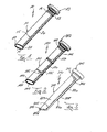
- filters 10, 110 and 210 preferably as a particle filter is designed for insertion into a particular curved filler neck of a container, preferably a tank for fuel, urea solutions or other liquids.
- the filter 10 has a filter sock 11,111 or 211 of a plastic mesh with a specific mesh size, which is molded onto a head 12, 112 and 212 of a graduated in diameter holder 13, 113, 213 made of plastic or otherwise secured.
- the filter sock 11, 111, 211 is a certain one depending on the used filling gun or the like and the filling pressure per unit time relatively long, is prevented according to the present invention, the one loosely net-like structure possessing filter sock 11, 111 and 211 at the onset of Filters 10, 110, 210 in a particular curved filler neck is neither damaged nor compressed or deformed in any other way.
- the filter 10, 110, 210 or its filter sock 11, 111, 211 has a stiffening arrangement 15, 115 or 215 which is flexible in at least partial areas.
- FIG. 1 shows the filter 10, the filter sleeve 11 is formed tubular-cylindrical over its entire length.
- the filter sock 11 has at its end facing away from the filling end 16 free end 17 a cover 18, which may be formed either of liquid-permeable sock material or liquid-impermeable solid material.
- the stiffening assembly 15 consists of a web-like or band-like stiffening element 20 which is connected at one end to the head 12 and the other end extends to the free end 17 of the filter sock 11.
- this made of plastic axial stiffening member 20 extends on an outer peripheral portion of the filter sleeve 11 over its entire axial length.
- the axial stiffening element 20 is connected to a plastic ring 21, which forms the circumferential connection between the free end 17 of the filter sleeve 11 of the cover 18.
- the stiffening element 20 preferably covers the non-visible longitudinal seam of the filter sock 11.
- the axial stiffening element 20 is wholly or in certain axial distances with the filter stocking 11, for example, punctiform connected or welded.
- the axial stiffening element 20 may have any cross-sections.
- the in FIG. 2 shown filter 110 is basically like the filter 10 after FIG. 1 constructed, with the stiffening assembly 115 is provided with additional stiffening elements 124 and 125 and equipped.
- the stiffening arrangement 115 for the filter sock 111 has an axially extending stiffening element 120, which corresponds to the stiffening element 20 of the filter 10 FIG. 1 equivalent.
- the axial bracing member 120 is provided in certain axial regions or sections with an additional bracing member or stiffening rib 124 and / or 125.
- the additional stiffening rib 124 is a closed ring, which leads around the hose-like cylindrical filter stocking 111 on the outer circumference side and is connected or integrated with the axial stiffening element 120.
- the additional stiffening rib 125 forms a unilaterally open ring, the opening side of the axial stiffening element 120 diametrically opposite. This additional stiffening rib 125 is also connected to the axial stiffening element 120 or in one piece.
- the stiffening ribs 124 and 125 may be the radial stiffening the axial stiffening element 120 additionally connected in a point-like manner with the filter sock 111.
- each one additional stiffening rib 124 and an additional stiffening rib 125 are shown, it is understood that depending on the axial length of the filter sock 111 either only one or more than two of the Stiffening elements 124 and / or 125 can be used.
- the filter sock 211 is not tube-like cylindrical over a part of its axial length but wedge-shaped like a tube, that is to say it has an approximately rectangular cross section (not shown) along an end region of certain axial length.
- the stiffening assembly 215 also has an axial stiffening member 220 extending along the outside of the cylindrical filter sock region and along a narrow side 228 of the wedge-shaped end portion 230 of the filter sock 211.
- This axial stiffening element 220 may also be connected or welded at certain axial intervals, for example, in a point-like manner to the cylindrical outer circumference or the narrow side 228 of the filter sock 211.
- the stiffening assembly 215 of the filter 210 according to FIG.
- the 3 also has an additional stiffening element 226, which is integral with the axial stiffening element 220 and is bent at a right angle thereto, so that this additional stiffening element 226 covers the free end 217 of the filter stocking 211 liquid-tight and is preferably firmly connected or welded.
- the free end 217 thus forms the wedge end, on which the two opposite and wedge-shaped mutually extending broad sides 229 of the filter sock 211 converge and are interconnected.
- the filter sock 211 of the filter 210 may be wedge-shaped over its entire length instead of only over a partial length, which connects the filter sump cylinder emanating from the filling end 216.
Landscapes
- Engineering & Computer Science (AREA)
- Chemical & Material Sciences (AREA)
- Chemical Kinetics & Catalysis (AREA)
- Life Sciences & Earth Sciences (AREA)
- Sustainable Development (AREA)
- Sustainable Energy (AREA)
- Combustion & Propulsion (AREA)
- Transportation (AREA)
- Mechanical Engineering (AREA)
- Details Of Rigid Or Semi-Rigid Containers (AREA)
- Filtering Materials (AREA)
- Filtration Of Liquid (AREA)
Claims (10)
- Filtre (10, 110, 210) destiné à être inséré dans une tubulure de remplissage en particulier courbée d'un récipient, de préférence d'un réservoir pour carburant, solution d'urée ou autres liquides, comprenant un manchon filtrant (11, 111, 211) dont l'extrémité de remplissage (16, 116, 216) est fixée sur une tête (12, 112, 212) d'un support (13, 113, 213) et dont l'extrémité libre (17, 117, 217) qui est opposée à ladite extrémité de remplissage (16, 116, 216) est couverte ou fermée, ledit manchon filtrant (11, 111, 211) étant pourvu d'un ensemble raidisseur (15, 115, 215) flexible partant de ladite tête de support (12, 112, 212) et s'étendant longitudinalement au moins en partie, caractérisé par le fait que l'élément raidisseur axial (20, 120, 220) dudit ensemble raidisseur (15, 115, 215) suit une couture de liaison dudit manchon filtrant (11, 111, 211) et couvre celle-ci.
- Filtre selon la revendication 1, caractérisé par le fait que ledit ensemble raidisseur (15, 115, 215) est prévu sur ledit manchon filtrant (11, 111, 211) sur la périphérie extérieure de celui-ci.
- Filtre selon la revendication 1 ou 2, caractérisé par le fait que ledit ensemble raidisseur (15, 115, 215) présente un élément raidisseur axial (20, 120, 220) qui s'étend à la manière d'une entretoise ou bande sur l'ensemble de la longueur du manchon filtrant (11, 111, 211).
- Filtre selon l'une au moins des revendications précédentes, caractérisé par le fait que ledit élément raidisseur axial (20, 120, 220) de l'ensemble raidisseur (15, 115, 215) est flexible dans l'une ou les deux des directions s'étendant perpendiculairement à l'extension longitudinale du manchon filtrant (11, 111, 211).
- Filtre selon l'une au moins des revendications précédentes, caractérisé par le fait que ledit élément raidisseur axial (120) de l'ensemble raidisseur (115) est pourvu, sur une ou plusieurs zones périphériques espacées axialement, de nervures raidisseuses (124, 125) ouvertes ou fermées sur la périphérie.
- Filtre selon l'une au moins des revendications 1 à 5, caractérisé par le fait que ledit manchon filtrant (11, 111) est cylindrique en forme de tuyau flexible sur l'ensemble de sa longueur et, à l'extrémité libre (17, 117) opposée à ladite extrémité de remplissage (16, 116), il est couvert par un disque (18, 118) en matière de manchon filtrant ou un disque imperméable et est entouré sur le bord par un anneau (21, 121) de l'ensemble raidisseur (15, 115).
- Filtre selon l'une au moins des revendications 1 à 5, caractérisé par le fait que ledit manchon filtrant (211), au moins sur une longueur partielle de la zone terminale opposée à l'extrémité de remplissage (216), est réuni en forme de coin vers ladite extrémité libre (217) qui est recouverte par une nervure (226) de l'ensemble raidisseur (215).
- Filtre selon l'une au moins des revendications précédentes, caractérisé par le fait que ledit ensemble raidisseur (15, 115, 215) est injecté sur la face extérieure sur ledit ou bien autour dudit manchon filtrant (11, 111, 211) injecté sur un noyau.
- Filtre selon l'une au moins des revendications précédentes, caractérisé par le fait que ledit ensemble raidisseur (15, 115, 215) est relié, au moins sur des zones partielles, audit manchon filtrant (11, 111, 211).
- Filtre selon l'une au moins des revendications précédentes, caractérisé par le fait qu'il est réalisé en tant que filtre à particules à partir d'un treillis en matière plastique.
Applications Claiming Priority (2)
| Application Number | Priority Date | Filing Date | Title |
|---|---|---|---|
| DE202011002684U DE202011002684U1 (de) | 2011-02-03 | 2011-02-03 | Filter zum Einsetzen in den Einfüllstutzen eines Behälters |
| PCT/EP2012/051858 WO2012104414A1 (fr) | 2011-02-03 | 2012-02-03 | Filtre destiné à être introduit dans la tubulure de remplissage d'un récipient |
Publications (2)
| Publication Number | Publication Date |
|---|---|
| EP2670614A1 EP2670614A1 (fr) | 2013-12-11 |
| EP2670614B1 true EP2670614B1 (fr) | 2015-01-07 |
Family
ID=45607225
Family Applications (1)
| Application Number | Title | Priority Date | Filing Date |
|---|---|---|---|
| EP12704024.4A Not-in-force EP2670614B1 (fr) | 2011-02-03 | 2012-02-03 | Filtre destiné à être introduit dans la tubulure de remplissage d'un récipient |
Country Status (3)
| Country | Link |
|---|---|
| EP (1) | EP2670614B1 (fr) |
| DE (1) | DE202011002684U1 (fr) |
| WO (1) | WO2012104414A1 (fr) |
Families Citing this family (6)
| Publication number | Priority date | Publication date | Assignee | Title |
|---|---|---|---|---|
| DE102013012917B4 (de) | 2013-08-05 | 2020-07-09 | Mann+Hummel Gmbh | Flüssigkeitsfilter, insbesondere für Kraftstoff |
| DE202013012843U1 (de) | 2013-08-05 | 2020-06-08 | Mann+Hummel Gmbh | Flüssigkeitsfilter, insbesondere für Kraftstoff |
| US9468875B2 (en) | 2014-01-14 | 2016-10-18 | Caterpillar Inc. | Filter system and filtration method for fluid reservoirs |
| US9248390B2 (en) | 2014-01-14 | 2016-02-02 | Caterpillar Inc. | Filter system and filtration method for fluid reservoirs |
| DE102015010082A1 (de) * | 2015-08-07 | 2017-02-09 | Mann+Hummel Gmbh | Wasserabscheideelement |
| WO2018112670A1 (fr) * | 2016-12-23 | 2018-06-28 | Westport Power Inc. | Appareil et procédé de filtration de fluide cryogénique |
Family Cites Families (9)
| Publication number | Priority date | Publication date | Assignee | Title |
|---|---|---|---|---|
| US1581947A (en) * | 1925-04-17 | 1926-04-20 | Hobbs Kermit | Gasoline filter |
| FR908341A (fr) * | 1944-12-19 | 1946-04-05 | Filtre pour les carburants liquides et gazeux | |
| US2647636A (en) * | 1948-09-21 | 1953-08-04 | Arthur W Rafferty | Unloading header fitting and strainer |
| US3826372A (en) * | 1973-06-14 | 1974-07-30 | Kuss R & Co Inc | Flexible filter |
| DE8124632U1 (de) * | 1981-08-22 | 1983-01-20 | Ferch, Alois, 4040 Neuss | Filter fuer fluessigkeiten, insbesondere fuer kraftstoff |
| DE19946551A1 (de) * | 1999-09-29 | 2001-04-05 | Mannesmann Vdo Ag | Zur Montage strömungsseitig vor einer Pumpe einer Scheibenreinigungsanlage eines Kraftfahrzeuges vorgesehener Filter |
| JP2001120920A (ja) * | 1999-10-21 | 2001-05-08 | Gp Daikyo Corp | オイルストレーナ |
| JP2004217141A (ja) * | 2003-01-17 | 2004-08-05 | Hitachi Constr Mach Co Ltd | 建設機械の燃料タンク |
| ITTO20090014U1 (it) * | 2009-02-09 | 2010-08-10 | Rototech S R L | Dispositivo di guida, di abilitazione al riempimento e di filtrazione per un serbatoio, in particolare per un serbatoio di soluzione di urea per un autoveicolo provvisto di un motore diesel |
-
2011
- 2011-02-03 DE DE202011002684U patent/DE202011002684U1/de not_active Expired - Lifetime
-
2012
- 2012-02-03 WO PCT/EP2012/051858 patent/WO2012104414A1/fr not_active Ceased
- 2012-02-03 EP EP12704024.4A patent/EP2670614B1/fr not_active Not-in-force
Also Published As
| Publication number | Publication date |
|---|---|
| EP2670614A1 (fr) | 2013-12-11 |
| DE202011002684U1 (de) | 2012-05-08 |
| WO2012104414A1 (fr) | 2012-08-09 |
Similar Documents
| Publication | Publication Date | Title |
|---|---|---|
| DE3813192C2 (fr) | ||
| EP3386811B1 (fr) | Support de tuyau pour bras d'essuie-glace, bras d'essuie-glace muni d'un support de tuyau, et procédé de production dudit support de tuyau | |
| WO2012104414A1 (fr) | Filtre destiné à être introduit dans la tubulure de remplissage d'un récipient | |
| EP2530799B1 (fr) | Dispositif de fermeture étanche d'une extrémité de tuyau de protection de câble | |
| AT517085A4 (de) | Steckverbinder zum Verbinden von Leitungen für flüssige oder gasförmige Medien | |
| WO2014023398A1 (fr) | Machine de construction routière | |
| EP2665901B1 (fr) | Tubulure de remplissage pour un réservoir de liquide, en particulier un réservoir d'urée, sur des véhicules automobiles | |
| WO2017089450A1 (fr) | Dispositif de protection pour un collier de serrage | |
| DE202011105646U1 (de) | Anschlussverbindung zwischen einem rohrförmigen Tankstutzen und einem flexiblen Rohr | |
| EP3118041B1 (fr) | Élement ameliore orientant l'ecoulement pour un manchon de remplissage de reservoir | |
| EP2012009B1 (fr) | Garniture de soupape de non-retour pour une pompe de dosage de carburant | |
| EP3217057A2 (fr) | Dispositif et procédé de fixation destiné à rendre étanche un passage de conduite dans une cloison d'un bâtiment | |
| DE4134367A1 (de) | Fluessigkeitsfilter | |
| EP2607133B1 (fr) | Agencement de tuyau de remplissage pour un récipient de réservoir de liquide pour véhicules automobiles | |
| DE7626528U1 (de) | Verbindungselement, insbesondere nippel | |
| DE10338065B4 (de) | Sicherheitsvorrichtung | |
| EP2759437A1 (fr) | Dispositif de remplissage d'au moins un réservoir de carburant disposé dans un véhicule automobile | |
| DE102014106047A1 (de) | Tank- oder Lademulde für ein Kraftfahrzeug | |
| DE20102217U1 (de) | Filter für Flüssigkeiten, insbesondere Kraftstoffe | |
| DE102014100247A1 (de) | Befüllvorrichtung für einen Fahrzeugtank | |
| DE202012012136U1 (de) | Abdeckung mit Einfüllstutzen | |
| EP2686568B1 (fr) | Dispositif d'amortissement | |
| DE112018002708B4 (de) | Behälter eines Reparatursets für Reifenlöcher | |
| DE102013110828B4 (de) | Einrichtung zum dichten Verschließen eines Tanks | |
| EP1795494B1 (fr) | Dispositif pour remplir et vider un conteneur |
Legal Events
| Date | Code | Title | Description |
|---|---|---|---|
| PUAI | Public reference made under article 153(3) epc to a published international application that has entered the european phase |
Free format text: ORIGINAL CODE: 0009012 |
|
| 17P | Request for examination filed |
Effective date: 20130514 |
|
| AK | Designated contracting states |
Kind code of ref document: A1 Designated state(s): AL AT BE BG CH CY CZ DE DK EE ES FI FR GB GR HR HU IE IS IT LI LT LU LV MC MK MT NL NO PL PT RO RS SE SI SK SM TR |
|
| DAX | Request for extension of the european patent (deleted) | ||
| GRAP | Despatch of communication of intention to grant a patent |
Free format text: ORIGINAL CODE: EPIDOSNIGR1 |
|
| INTG | Intention to grant announced |
Effective date: 20140516 |
|
| GRAS | Grant fee paid |
Free format text: ORIGINAL CODE: EPIDOSNIGR3 |
|
| GRAP | Despatch of communication of intention to grant a patent |
Free format text: ORIGINAL CODE: EPIDOSNIGR1 |
|
| INTG | Intention to grant announced |
Effective date: 20140930 |
|
| GRAA | (expected) grant |
Free format text: ORIGINAL CODE: 0009210 |
|
| AK | Designated contracting states |
Kind code of ref document: B1 Designated state(s): AL AT BE BG CH CY CZ DE DK EE ES FI FR GB GR HR HU IE IS IT LI LT LU LV MC MK MT NL NO PL PT RO RS SE SI SK SM TR |
|
| REG | Reference to a national code |
Ref country code: GB Ref legal event code: FG4D Free format text: NOT ENGLISH |
|
| REG | Reference to a national code |
Ref country code: CH Ref legal event code: EP |
|
| REG | Reference to a national code |
Ref country code: IE Ref legal event code: FG4D Free format text: LANGUAGE OF EP DOCUMENT: GERMAN |
|
| REG | Reference to a national code |
Ref country code: AT Ref legal event code: REF Ref document number: 705433 Country of ref document: AT Kind code of ref document: T Effective date: 20150215 |
|
| REG | Reference to a national code |
Ref country code: DE Ref legal event code: R096 Ref document number: 502012002042 Country of ref document: DE Effective date: 20150226 |
|
| REG | Reference to a national code |
Ref country code: NL Ref legal event code: VDEP Effective date: 20150107 |
|
| REG | Reference to a national code |
Ref country code: LT Ref legal event code: MG4D |
|
| PG25 | Lapsed in a contracting state [announced via postgrant information from national office to epo] |
Ref country code: BE Free format text: LAPSE BECAUSE OF NON-PAYMENT OF DUE FEES Effective date: 20150228 |
|
| PG25 | Lapsed in a contracting state [announced via postgrant information from national office to epo] |
Ref country code: NO Free format text: LAPSE BECAUSE OF FAILURE TO SUBMIT A TRANSLATION OF THE DESCRIPTION OR TO PAY THE FEE WITHIN THE PRESCRIBED TIME-LIMIT Effective date: 20150407 Ref country code: FI Free format text: LAPSE BECAUSE OF FAILURE TO SUBMIT A TRANSLATION OF THE DESCRIPTION OR TO PAY THE FEE WITHIN THE PRESCRIBED TIME-LIMIT Effective date: 20150107 Ref country code: SE Free format text: LAPSE BECAUSE OF FAILURE TO SUBMIT A TRANSLATION OF THE DESCRIPTION OR TO PAY THE FEE WITHIN THE PRESCRIBED TIME-LIMIT Effective date: 20150107 Ref country code: HR Free format text: LAPSE BECAUSE OF FAILURE TO SUBMIT A TRANSLATION OF THE DESCRIPTION OR TO PAY THE FEE WITHIN THE PRESCRIBED TIME-LIMIT Effective date: 20150107 Ref country code: BG Free format text: LAPSE BECAUSE OF FAILURE TO SUBMIT A TRANSLATION OF THE DESCRIPTION OR TO PAY THE FEE WITHIN THE PRESCRIBED TIME-LIMIT Effective date: 20150407 Ref country code: ES Free format text: LAPSE BECAUSE OF FAILURE TO SUBMIT A TRANSLATION OF THE DESCRIPTION OR TO PAY THE FEE WITHIN THE PRESCRIBED TIME-LIMIT Effective date: 20150107 Ref country code: LT Free format text: LAPSE BECAUSE OF FAILURE TO SUBMIT A TRANSLATION OF THE DESCRIPTION OR TO PAY THE FEE WITHIN THE PRESCRIBED TIME-LIMIT Effective date: 20150107 |
|
| PG25 | Lapsed in a contracting state [announced via postgrant information from national office to epo] |
Ref country code: RS Free format text: LAPSE BECAUSE OF FAILURE TO SUBMIT A TRANSLATION OF THE DESCRIPTION OR TO PAY THE FEE WITHIN THE PRESCRIBED TIME-LIMIT Effective date: 20150107 Ref country code: NL Free format text: LAPSE BECAUSE OF FAILURE TO SUBMIT A TRANSLATION OF THE DESCRIPTION OR TO PAY THE FEE WITHIN THE PRESCRIBED TIME-LIMIT Effective date: 20150107 Ref country code: LV Free format text: LAPSE BECAUSE OF FAILURE TO SUBMIT A TRANSLATION OF THE DESCRIPTION OR TO PAY THE FEE WITHIN THE PRESCRIBED TIME-LIMIT Effective date: 20150107 Ref country code: IS Free format text: LAPSE BECAUSE OF FAILURE TO SUBMIT A TRANSLATION OF THE DESCRIPTION OR TO PAY THE FEE WITHIN THE PRESCRIBED TIME-LIMIT Effective date: 20150507 Ref country code: GR Free format text: LAPSE BECAUSE OF FAILURE TO SUBMIT A TRANSLATION OF THE DESCRIPTION OR TO PAY THE FEE WITHIN THE PRESCRIBED TIME-LIMIT Effective date: 20150408 Ref country code: PL Free format text: LAPSE BECAUSE OF FAILURE TO SUBMIT A TRANSLATION OF THE DESCRIPTION OR TO PAY THE FEE WITHIN THE PRESCRIBED TIME-LIMIT Effective date: 20150107 |
|
| REG | Reference to a national code |
Ref country code: CH Ref legal event code: PL |
|
| REG | Reference to a national code |
Ref country code: DE Ref legal event code: R097 Ref document number: 502012002042 Country of ref document: DE |
|
| PG25 | Lapsed in a contracting state [announced via postgrant information from national office to epo] |
Ref country code: MC Free format text: LAPSE BECAUSE OF FAILURE TO SUBMIT A TRANSLATION OF THE DESCRIPTION OR TO PAY THE FEE WITHIN THE PRESCRIBED TIME-LIMIT Effective date: 20150107 Ref country code: DK Free format text: LAPSE BECAUSE OF FAILURE TO SUBMIT A TRANSLATION OF THE DESCRIPTION OR TO PAY THE FEE WITHIN THE PRESCRIBED TIME-LIMIT Effective date: 20150107 Ref country code: EE Free format text: LAPSE BECAUSE OF FAILURE TO SUBMIT A TRANSLATION OF THE DESCRIPTION OR TO PAY THE FEE WITHIN THE PRESCRIBED TIME-LIMIT Effective date: 20150107 Ref country code: CH Free format text: LAPSE BECAUSE OF NON-PAYMENT OF DUE FEES Effective date: 20150228 Ref country code: RO Free format text: LAPSE BECAUSE OF FAILURE TO SUBMIT A TRANSLATION OF THE DESCRIPTION OR TO PAY THE FEE WITHIN THE PRESCRIBED TIME-LIMIT Effective date: 20150107 Ref country code: LI Free format text: LAPSE BECAUSE OF NON-PAYMENT OF DUE FEES Effective date: 20150228 Ref country code: SK Free format text: LAPSE BECAUSE OF FAILURE TO SUBMIT A TRANSLATION OF THE DESCRIPTION OR TO PAY THE FEE WITHIN THE PRESCRIBED TIME-LIMIT Effective date: 20150107 Ref country code: CZ Free format text: LAPSE BECAUSE OF FAILURE TO SUBMIT A TRANSLATION OF THE DESCRIPTION OR TO PAY THE FEE WITHIN THE PRESCRIBED TIME-LIMIT Effective date: 20150107 |
|
| PLBE | No opposition filed within time limit |
Free format text: ORIGINAL CODE: 0009261 |
|
| STAA | Information on the status of an ep patent application or granted ep patent |
Free format text: STATUS: NO OPPOSITION FILED WITHIN TIME LIMIT |
|
| REG | Reference to a national code |
Ref country code: IE Ref legal event code: MM4A |
|
| REG | Reference to a national code |
Ref country code: FR Ref legal event code: ST Effective date: 20151030 |
|
| 26N | No opposition filed |
Effective date: 20151008 |
|
| PG25 | Lapsed in a contracting state [announced via postgrant information from national office to epo] |
Ref country code: IT Free format text: LAPSE BECAUSE OF FAILURE TO SUBMIT A TRANSLATION OF THE DESCRIPTION OR TO PAY THE FEE WITHIN THE PRESCRIBED TIME-LIMIT Effective date: 20150107 |
|
| PG25 | Lapsed in a contracting state [announced via postgrant information from national office to epo] |
Ref country code: IE Free format text: LAPSE BECAUSE OF NON-PAYMENT OF DUE FEES Effective date: 20150203 |
|
| PG25 | Lapsed in a contracting state [announced via postgrant information from national office to epo] |
Ref country code: SI Free format text: LAPSE BECAUSE OF FAILURE TO SUBMIT A TRANSLATION OF THE DESCRIPTION OR TO PAY THE FEE WITHIN THE PRESCRIBED TIME-LIMIT Effective date: 20150107 Ref country code: FR Free format text: LAPSE BECAUSE OF NON-PAYMENT OF DUE FEES Effective date: 20150309 |
|
| GBPC | Gb: european patent ceased through non-payment of renewal fee |
Effective date: 20160203 |
|
| PG25 | Lapsed in a contracting state [announced via postgrant information from national office to epo] |
Ref country code: MT Free format text: LAPSE BECAUSE OF FAILURE TO SUBMIT A TRANSLATION OF THE DESCRIPTION OR TO PAY THE FEE WITHIN THE PRESCRIBED TIME-LIMIT Effective date: 20150107 |
|
| PG25 | Lapsed in a contracting state [announced via postgrant information from national office to epo] |
Ref country code: GB Free format text: LAPSE BECAUSE OF NON-PAYMENT OF DUE FEES Effective date: 20160203 |
|
| PG25 | Lapsed in a contracting state [announced via postgrant information from national office to epo] |
Ref country code: HU Free format text: LAPSE BECAUSE OF FAILURE TO SUBMIT A TRANSLATION OF THE DESCRIPTION OR TO PAY THE FEE WITHIN THE PRESCRIBED TIME-LIMIT; INVALID AB INITIO Effective date: 20120203 Ref country code: SM Free format text: LAPSE BECAUSE OF FAILURE TO SUBMIT A TRANSLATION OF THE DESCRIPTION OR TO PAY THE FEE WITHIN THE PRESCRIBED TIME-LIMIT Effective date: 20150107 |
|
| PG25 | Lapsed in a contracting state [announced via postgrant information from national office to epo] |
Ref country code: CY Free format text: LAPSE BECAUSE OF FAILURE TO SUBMIT A TRANSLATION OF THE DESCRIPTION OR TO PAY THE FEE WITHIN THE PRESCRIBED TIME-LIMIT Effective date: 20150107 |
|
| PG25 | Lapsed in a contracting state [announced via postgrant information from national office to epo] |
Ref country code: PT Free format text: LAPSE BECAUSE OF FAILURE TO SUBMIT A TRANSLATION OF THE DESCRIPTION OR TO PAY THE FEE WITHIN THE PRESCRIBED TIME-LIMIT Effective date: 20150507 |
|
| PG25 | Lapsed in a contracting state [announced via postgrant information from national office to epo] |
Ref country code: TR Free format text: LAPSE BECAUSE OF FAILURE TO SUBMIT A TRANSLATION OF THE DESCRIPTION OR TO PAY THE FEE WITHIN THE PRESCRIBED TIME-LIMIT Effective date: 20150107 |
|
| PG25 | Lapsed in a contracting state [announced via postgrant information from national office to epo] |
Ref country code: LU Free format text: LAPSE BECAUSE OF NON-PAYMENT OF DUE FEES Effective date: 20150203 |
|
| REG | Reference to a national code |
Ref country code: AT Ref legal event code: MM01 Ref document number: 705433 Country of ref document: AT Kind code of ref document: T Effective date: 20170203 |
|
| PG25 | Lapsed in a contracting state [announced via postgrant information from national office to epo] |
Ref country code: AT Free format text: LAPSE BECAUSE OF NON-PAYMENT OF DUE FEES Effective date: 20170203 |
|
| PG25 | Lapsed in a contracting state [announced via postgrant information from national office to epo] |
Ref country code: MK Free format text: LAPSE BECAUSE OF FAILURE TO SUBMIT A TRANSLATION OF THE DESCRIPTION OR TO PAY THE FEE WITHIN THE PRESCRIBED TIME-LIMIT Effective date: 20150107 |
|
| PGFP | Annual fee paid to national office [announced via postgrant information from national office to epo] |
Ref country code: DE Payment date: 20180423 Year of fee payment: 7 |
|
| PG25 | Lapsed in a contracting state [announced via postgrant information from national office to epo] |
Ref country code: AL Free format text: LAPSE BECAUSE OF FAILURE TO SUBMIT A TRANSLATION OF THE DESCRIPTION OR TO PAY THE FEE WITHIN THE PRESCRIBED TIME-LIMIT Effective date: 20150107 |
|
| REG | Reference to a national code |
Ref country code: DE Ref legal event code: R119 Ref document number: 502012002042 Country of ref document: DE |
|
| PG25 | Lapsed in a contracting state [announced via postgrant information from national office to epo] |
Ref country code: DE Free format text: LAPSE BECAUSE OF NON-PAYMENT OF DUE FEES Effective date: 20190903 |