EP3217057A2 - Dispositif et procédé de fixation destiné à rendre étanche un passage de conduite dans une cloison d'un bâtiment - Google Patents
Dispositif et procédé de fixation destiné à rendre étanche un passage de conduite dans une cloison d'un bâtiment Download PDFInfo
- Publication number
- EP3217057A2 EP3217057A2 EP17156192.1A EP17156192A EP3217057A2 EP 3217057 A2 EP3217057 A2 EP 3217057A2 EP 17156192 A EP17156192 A EP 17156192A EP 3217057 A2 EP3217057 A2 EP 3217057A2
- Authority
- EP
- European Patent Office
- Prior art keywords
- passage
- wall
- channel
- building
- sealing
- Prior art date
- Legal status (The legal status is an assumption and is not a legal conclusion. Google has not performed a legal analysis and makes no representation as to the accuracy of the status listed.)
- Granted
Links
Images





Classifications
-
- F—MECHANICAL ENGINEERING; LIGHTING; HEATING; WEAPONS; BLASTING
- F16—ENGINEERING ELEMENTS AND UNITS; GENERAL MEASURES FOR PRODUCING AND MAINTAINING EFFECTIVE FUNCTIONING OF MACHINES OR INSTALLATIONS; THERMAL INSULATION IN GENERAL
- F16L—PIPES; JOINTS OR FITTINGS FOR PIPES; SUPPORTS FOR PIPES, CABLES OR PROTECTIVE TUBING; MEANS FOR THERMAL INSULATION IN GENERAL
- F16L5/00—Devices for use where pipes, cables or protective tubing pass through walls or partitions
- F16L5/02—Sealing
-
- G—PHYSICS
- G02—OPTICS
- G02B—OPTICAL ELEMENTS, SYSTEMS OR APPARATUS
- G02B6/00—Light guides; Structural details of arrangements comprising light guides and other optical elements, e.g. couplings
- G02B6/44—Mechanical structures for providing tensile strength and external protection for fibres, e.g. optical transmission cables
- G02B6/4439—Auxiliary devices
- G02B6/4459—Ducts; Conduits; Hollow tubes for air blown fibres
-
- G—PHYSICS
- G02—OPTICS
- G02B—OPTICAL ELEMENTS, SYSTEMS OR APPARATUS
- G02B6/00—Light guides; Structural details of arrangements comprising light guides and other optical elements, e.g. couplings
- G02B6/46—Processes or apparatus adapted for installing or repairing optical fibres or optical cables
- G02B6/47—Installation in buildings
- G02B6/475—Mechanical aspects of installing cables in ducts or the like for buildings
-
- H—ELECTRICITY
- H02—GENERATION; CONVERSION OR DISTRIBUTION OF ELECTRIC POWER
- H02G—INSTALLATION OF ELECTRIC CABLES OR LINES, OR OF COMBINED OPTICAL AND ELECTRIC CABLES OR LINES
- H02G3/00—Installations of electric cables or lines or protective tubing therefor in or on buildings, equivalent structures or vehicles
- H02G3/22—Installations of cables or lines through walls, floors or ceilings, e.g. into buildings
Definitions
- a generic device for fastening and sealing the leading through a wall opening of the building wall line bushing, such as a conduit, is off EP 2 410 222 B1 known.
- a distributor sleeve as a rigid passage tube is arranged at a distance concentrically between the passage wall and the empty tube to be fastened, wherein a sealing bead is provided on a building wall outside, which can be clamped against the building wall outside via a clamping device to be operated on the building wall inside.
- a filling tube is deeply inserted, over the in the middle of a hollow block of the building wall a viscous flowing Aushärtsubstanz can be introduced.
- the distributor sleeve comprises a sleeve-shaped sealing end or sealing sleeve facing in particular the building interior side.
- the sealing end preferably forms a cylindrical inner sealing surface which has an inner diameter which is adapted to a particularly constant outer diameter of the conduit feedthrough, such as the empty tube, such that a clearance-free fit, in particular a transition fit or press fit, is formed between the conduit feedthrough and the distributor sleeve. in particular in order to realize a seal against an axial exit of the curing substance from the annular gap space.
- the invention relates to the distributor sleeve itself, which can be used in particular with the above-mentioned fastening and sealing device.
- the distributor sleeve serves to enclose the conduit bushing, such as the empty tube, in particular concentrically and thereby to form the annular, in particular annular, circumferential gap space. In the gap, the flowable Aushärtsubstanz should be introduced.
- the manifold collar has a rigid or flexible sheath body having a plurality of through holes for radially passing the curing substance from the inside of the manifold collar to the outside thereof to make contact with the inside of the building wall passageway.
- the distributor sleeve in particular at an axial end section, has a contact flange, in particular for application to a building side, preferably a building exterior wall, in order to impart a clear axial and optionally also a radial position to the enveloping body for mounting the distribution collar, in particular the sealing and fastening device.
- the abutment flange has a connection via which the curing substance is to be introduced into the gap space.
- the port can be used to connect an external curing agent source.
- the port includes an inlet channel for guiding the particular pasty Aushärtsubstanz in the gap.
- At least the enveloping body and the connection with the channel wall boundary of the inlet duct and optionally the abutment flange are made of a piece of material, in particular molded from a piece of plastic. It was found that with this technical measure an extremely compact distribution collar and a compact sealing and fastening device can be achieved and the gap space can be formed with a significantly lower volume. In this way, the Belegevolumen the empty tube can be significantly increased. It has also been found that the operability of the sealing and fastening device in the assembly and in the injection of the Aushärtsubstanz is significantly simplified, because according to the invention a violation of the separate line structures is largely excluded.
- the inlet channel has a connection-side channel end section which extends from a free connection end axially, in particular substantially to the axial height of a contact surface of the contact flange or the building contact surface and / or substantially has a cylindrical passage cross-section.
- the inlet channel has a transition channel portion which connects in the axial direction stepwise at the channel end portion.
- the radial outer boundary walls of the transition channel portion jump radially inwardly of the outer boundary walls of the channel end portion, thereby reducing a radial height of the channel cross section.
- the circumferential wall portion of the channel is widened to compensate for a reduction in cross-section, or at least to keep small or completely compensate.
- the transition channel portion has a radially-inside passage opening through which a fluid connection between the inlet channel and the gap space is achieved.
- the outer wall of the channel transition section is widened radially outwards relative to the outer wall of the longitudinally extending distribution channel, which is formed on the inside of the enveloping body by the particular cylindrical enveloping body, preferably by less than 3 mm, the offset outer wall being more than 10 mm extends in the axial longitudinal direction of the contact surface into the interior of the wall passage and then opens into the cylindrical envelope body by means of a step disappearing.
- the wall thickness along the entire inlet channel from the port to the gap space is substantially constant.
- a channel inner wall of the channel transition section, in particular in the region of the axial height of the contact surface can be provided with a passage opening for the fluidic connection of the inlet channel to the distribution channel adjoining the transition channel.
- the passage opening can extend axially by at least 5 mm in the longitudinal direction, wherein it has a smaller circumferential width than axial length.
- a channel boundary wall section of the enveloping body located at the top (radially on the outside) is free of any through holes and / or slots.
- the Kanalbegrenzungswandabites without through holes may have a minimum circumferential width of at least 5 mm, in particular, the through hole-free Hüll stressesabites extends in the longitudinal direction by at least half of the longitudinal extent of the enveloping body.
- the through hole-free Hüll stressesabites includes at least one row of particular identical through holes and / or slots.
- the invention relates to a hose-like, in particular membrane-like, in particular manually deformable, flexible distributor sleeve for the device for fastening and sealing the through a wall passage leading through the building wall line bushing, as defined above, for example.
- the cable feedthrough can be an empty tube in which the electrical conductors or optical waveguides are to be arranged.
- the attachment of the flexible distributor sleeve is to be done on and opposite the building wall, wherein the flexible distributor sleeve forms with the line feedthrough, to which it can be arranged concentrically, an annular, in particular annular, circumferential gap.
- the manifold collar has a plurality of passage slots formed by slots having a minimum slot width of at least 0.3 mm, 0.4 mm or 0.5 mm.
- the slot length and the slot width are dimensioned such that in the assembled state, in particular when applying a Aushärtsubstanztiks on the distributor sleeve, the opposite slot edges do not come into contact but the slot remains open to ensure passage of the Aushärtsubstanz.
- the injection pressure of the hardening substance into the gap space need not be applied to provide a passage area in the slot.
- the flexible distribution sleeve is made of a piece of elastomeric material, in particular injected.
- at least one slot row extending in the axial longitudinal direction of the distributor sleeve is provided with slots arranged in the same slot orientation, preferably with the same slot length and width.
- two mutually adjacent rows of slots can each have a mutually different slot length, in particular, a difference in length of at least 5 mm, 1 cm or 2 cm, in particular, the slot width of the slots of both rows of slots, in particular all rows of slots, is substantially equal.
- the slots are already realized in the context of manufacturing the flexible distributor sleeve, for example by a corresponding injection molding method.
- the invention relates to a rigid distribution sleeve, in particular of a rigid material, such as metal or plastic, for a particular device described above for attaching and sealing a leading through the wall passage of the building wall line bushing, such as a conduit, on and opposite the building wall and for enclosing the line bushing to form a ring-shaped, in particular annular, surrounding gap space.
- a flowable Aushärtsubstanz can be introduced, which realizes the final sealing function and attachment function.
- the rigid distributor sleeve comprises an enveloping body with a plurality of passage openings, through which the hardening substance can emerge from the gap space towards the wall passage.
- the passage openings each have an oblong hole shape, wherein their passage width, which is constant, in particular in the slot longitudinal direction, is less than 1 mm and greater than 3 mm, preferably between 0.4 mm and 0.8 mm.
- this slot size proved to be advantageous in that a sufficient fürlouquanttician can be realized through the passages, without affecting the stability of the envelope too strong.
- a uniform distribution of the above-dimensioned elongated holes ensures a large-volume distribution of Aushärtsubstanz, which on the one hand, an improved sealing effect and a stronger attachment resistance can be generated.
- an area ratio between a total passage cross section of the passage openings, which results from the sum of all passage cross sections of the passage opening in the enveloping body, and the total outer circumference of the particular cylindrical enveloping body is greater than 0.5 and less than 0.7, preferably between 0 , 52 and 0.6, in particular between 0.55 and 0.65.
- a first passage long hole row has a short hole length of less than 4 mm and another with a long slot length greater than 4 mm or 5 mm.
- the enveloping body has a passageway-free bridge area having a width of at least 4 mm, 5 mm or 6 mm.
- the passage-free hole-free region extends at least half of the total length of the enveloping body, in particular has the same length as the inside distribution channel.
- the sealing and fastening device is formed with an above-mentioned sleeve depending on the design.
- the invention relates to a leading through a wall passage of a building wall line bushing, such as a conduit, on and opposite the building wall.
- a distributor sleeve is preferably dimensioned such that, in particular in the case of a concentric arrangement of the distributor sleeve around the cable feedthrough, an annular gap is formed whose radial width is in particular greater than 0.5 mm and in particular less than 5 mm.
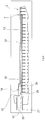
- Fig. 2 the device 1 according to the invention for fastening and sealing the empty tube 5 is shown in cross section, wherein the clamping and sealing device 7 is mounted in the empty tube 5.
- a driver slides in the axial direction, whereby two Abdichtwülste 29 are axially compressed and expand radially to form an enclosing sealing contact with the inside of the empty tube 5.
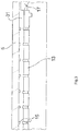
- the enveloping body 13 comprises a plurality of substantially uniformly distributed passage elongated holes 15, which are arranged in several axial rows one behind the other at substantially the same axial distance. The arrangement of the passage-long holes 15 will be described later particularly with reference to FIG 10 and 11 received.
- a side of the abutment flange 11 a integrally formed with the abutment flange 11 connecting or injection nozzle 21 is formed, which forms a Kanalendabêt 22 or inlet channel in particular circular cylindrical cross-section, with the formed on the inside of the envelope body distribution channel 19 for forwarding the Aushärtsubstanz is connected beyond the center of the envelope 13 addition.
- the injection nozzle 21 forms the circular cylindrical connector for easy connection of an injection tube or other filling aid (not shown), and has an inner diameter of 5 mm to 20 mm, in particular about 10 mm.
- a pasty, flow-like curing substance such as Tangit
- the connecting piece 21 is arranged eccentrically to the longitudinal axis L of the distributor sleeve 3 substantially at a radial height r of the cylindrical envelope 13, which corresponds substantially to the maximum radial distance of the distributor sleeve 3, in particular slightly larger than the maximum radial distance of the outer periphery of the empty tube 5 to the longitudinal axis L. and is slightly smaller than the radial distance of the inside of the wall passage 18 to the longitudinal axis L.
- the distribution channel 19 extends axially not over the entire longitudinal extent of the envelope 13 but over at least half but less than three-quarters of the total longitudinal extent of the envelope 13.
- the distribution channel 19 ends with the jumping back of the long ribs 32 to the inside of the cylindrical envelope 13th This exit point is provided with the reference numeral u.
- the distribution channel 19 is a partial ring section in cross section and changes its cross section in the region of the dome-shaped expansion 16, which is formed in the axial connection to the abutment flange 11.
- the distribution channel 19 is bounded radially on the outside by the correspondingly assigned cylindrical section of the enveloping body 13.
- An additional stabilizing rib 33 which is provided for stabilizing / centering the enveloping body 13 on the empty tube 5, is assigned to the pair of longitudinal ribs 32 substantially diametrically opposite the longitudinal axis L.
- the long ribs 32 and the stabilizing rib 33 are made in one piece with the enveloping body 13, in particular made of plastic.
- the stabilizing rib 33 extends in the axial direction as far as the long ribs 32 in order to achieve an unhindered distribution of the curing substance in the rib-free end region of the distributor sleeve 3.
- the radial widening 16 of the enveloping body 13 Adjacent to the building exterior wall side A protruding a few millimeters into the wall passage, the radial widening 16 of the enveloping body 13 is formed on the outer region of a transition duct section connecting the distribution passage 19 with the inlet passage.
- the expansion 16 and the radial outer boundary region of the distribution channel 19 in the axial connection to the expansion 16 should be formed according to a preferred embodiment of the invention free of any passage opening, so as to ensure that the amount of injected Aushärtsubstanz loss-free reaches the exit region u of the distribution channel 19 , With regard to the radially outer injection nozzle half of the injection nozzle 21, a transition channel portion 20 forms a radial recess despite the widening 16.
- the passage cross-section of the injection nozzle is substantially circular to the contact surface 10, wherein in the region of the transition channel portion 20, which comprises the expansion 16, a sudden cross-sectional reduction is provided.
- the transition duct section 20 extends axially into the wall passage 18 via the position of the contact surface 10, wherein the transition duct section 20 is initially delimited axially on the inside by the neck extension 25.
- Several millimeters, in particular 5 mm to 15 mm from the reduction of the passage cross-section ends the nozzle extension 25 and opens into the inside passage opening 26.
- On the outside and in the circumferential direction of the transition channel portion 20 is limited by the expansion 16 and by the long ribs 32.
- the distribution channel 19 allows leakage in the circumferential direction only from the point u, so that in the entire gap 31 from the field u a pasty Aushärtmaterial passes, which can be introduced via the injection nozzle 21. From the point u, the Aushärtsubstanz distributed in the circumferential direction, radial direction and axial direction uniformly in both the gap 31 and in the direction of the building exterior wall side A.
- the injection nozzle 21, the abutment flange 11 and the enveloping body 13 and the distribution channels 19 limiting long ribs 32 are made of a Injected plastic piece.
- passage longitudinal holes 15 are introduced to provide a radial escape of the flowable Aushärtsubstanz (not shown) from the filled via the injection nozzle 21 gap 31 in the radial direction to the outside of the envelope 13 and towards the inside of the wall passage 18.
- the long hole extension of the through holes 15 is aligned in the circumferential direction, that is perpendicular to the longitudinal axis L, wherein the circumferential length of the passage-long holes 15 may be different for each row.
- the circumferential length of the passage long holes 15 may be constant.
- the passage-long holes 15 are arranged at an equal axial distance from each other in all rows.
- the axial rows of the passage-long holes 15 are separated by a continuous bridge portion 45 of the envelope body (13) of 1 mm to 5 mm, each bridge section 15 two circumferentially adjacent through holes 15 separated from each other.
- the distributor sleeve 3 is provided on the entire circumference with the passage longitudinal holes, which is dimensioned such that a sufficient occurrence of the Aushärtsubstanz from the gap 31 to the inside of the wall passage 18 is ensured. Only in the circumferential and longitudinal extent of the distribution channel 19, no passages in the enveloping body 13 are formed.
- the passage-long holes 15 are each arranged in a row, with the passage-long holes 15 of each row having the same length or circumferential extent.
- Adjacent to the distribution channel 19 are each a row of slot rows arranged with a first length, in particular of 6 mm, the adjacent slot row may have a second length in particular of 3.5 mm.
- the passage-long holes 15 are introduced either in a flexibly deformable envelope 13 or in a rigid sleeve body 13.
- the slots are greater than 0.3 mm in width and smaller than 1 mm, preferably between 0.4 mm and 0, 8 mm, formed.
- the passage-long holes 15 are formed as part of the manufacturing process, In particular, the injection molding process of the enveloping body 13 and can be prepared so dimensionally accurate that a post-processing of the passage-long holes 15 is not necessary. It is clear that in particular with a rigid material for the enveloping body 13, a material removal method, such as punching or sawing, can be used.
- the passage-long holes 15 are in particular formed so wide that the opposite slot sides do not touch in the mounted state, but the fürgangslanglochö réelle always remains open, even if no Aushärtsubstanz is introduced.
- the flexible, tubular casing body 13 may be formed of a rubber-elastic material and have a wall thickness of less than 1 mm.
- the shell body 13 can also be formed by a rigid material, in particular a plastic material, preferably a thermoset material or a thermoplastic material, and have a wall thickness of more than 2 mm.
Landscapes
- Physics & Mathematics (AREA)
- Engineering & Computer Science (AREA)
- General Physics & Mathematics (AREA)
- Optics & Photonics (AREA)
- General Engineering & Computer Science (AREA)
- Civil Engineering (AREA)
- Structural Engineering (AREA)
- Mechanical Engineering (AREA)
- Installation Of Indoor Wiring (AREA)
- Laying Of Electric Cables Or Lines Outside (AREA)
Applications Claiming Priority (1)
| Application Number | Priority Date | Filing Date | Title |
|---|---|---|---|
| DE102016104129.7A DE102016104129B4 (de) | 2016-03-07 | 2016-03-07 | Vorrichtung, Verteilermanschette und Verfahren zum Befestigen und Abdichten einer Leitungsdurchführung in einem Wanddurchgang einer Gebäudewand |
Publications (3)
| Publication Number | Publication Date |
|---|---|
| EP3217057A2 true EP3217057A2 (fr) | 2017-09-13 |
| EP3217057A3 EP3217057A3 (fr) | 2017-10-25 |
| EP3217057B1 EP3217057B1 (fr) | 2020-07-22 |
Family
ID=58098448
Family Applications (1)
| Application Number | Title | Priority Date | Filing Date |
|---|---|---|---|
| EP17156192.1A Active EP3217057B1 (fr) | 2016-03-07 | 2017-02-15 | Dispositif et procédé de fixation destiné à rendre étanche un passage de conduite dans une cloison d'un bâtiment |
Country Status (6)
| Country | Link |
|---|---|
| EP (1) | EP3217057B1 (fr) |
| DE (1) | DE102016104129B4 (fr) |
| DK (1) | DK3217057T3 (fr) |
| ES (1) | ES2828301T3 (fr) |
| HU (1) | HUE052458T2 (fr) |
| PT (1) | PT3217057T (fr) |
Cited By (3)
| Publication number | Priority date | Publication date | Assignee | Title |
|---|---|---|---|---|
| EP3624284A1 (fr) * | 2018-09-14 | 2020-03-18 | Langmatz GmbH | Dispositif de passage d'un speedpipe à travers un trou dans un mur |
| CN110985763A (zh) * | 2019-12-13 | 2020-04-10 | 北京建工集团山西建设有限公司 | 穿越混凝土基础底板地源热泵管的防水结构及其施做方法 |
| EP3719945A1 (fr) * | 2019-04-05 | 2020-10-07 | Langmatz GmbH | Dispositif de pose d'au moins une conduite dans un trou d'un mur |
Families Citing this family (1)
| Publication number | Priority date | Publication date | Assignee | Title |
|---|---|---|---|---|
| DE102019133788B4 (de) * | 2019-12-10 | 2021-06-17 | Langmatz Gmbh | Vorrichtung zum Durchführen wenigstens eines Glasfaser-Kabels durch eine Wandbohrung |
Citations (3)
| Publication number | Priority date | Publication date | Assignee | Title |
|---|---|---|---|---|
| EP2071688B1 (fr) | 2007-12-14 | 2011-11-30 | Hauff-Technik GmbH & Co. KG | Passage de câbles à travers un mur de bâtiment |
| DE102010026082A1 (de) | 2010-07-05 | 2012-01-05 | Gabo Systemtechnik Gmbh | Vorrichtung zum Durchführen wenigstens einer Leitung und Wanddurchführungssystem für wenigstens eine Leitung |
| EP2410222B1 (fr) | 2010-07-21 | 2012-11-07 | Langmatz GmbH | Dispositif de fixation et d'étanchéification d'une conduite passant à travers une ouverture de mur de bâtiment |
Family Cites Families (6)
| Publication number | Priority date | Publication date | Assignee | Title |
|---|---|---|---|---|
| US2897533A (en) * | 1956-02-16 | 1959-08-04 | Gen Motors Corp | Grommets, bushings and the like |
| WO2007028443A1 (fr) * | 2005-07-13 | 2007-03-15 | Beele Engineering B.V. | Système pour étanchéiser un espace entre une paroi interne d’une ouverture tubulaire et au moins un tube ou conduit reçu au moins partiellement dans l’ouverture |
| JP5617706B2 (ja) * | 2011-03-14 | 2014-11-05 | 住友電装株式会社 | グロメットのシール構造 |
| DE202012002751U1 (de) * | 2012-03-16 | 2013-06-18 | Doyma Gmbh & Co | LWL-Hauseinführung |
| PL2744058T3 (pl) * | 2012-03-29 | 2017-12-29 | Hauff-Technik Gmbh & Co. Kg | Przepust przewodowy do mocowania w ścianie budynku |
| DE202014009256U1 (de) * | 2014-11-21 | 2015-02-27 | Ubt Unit Building Technologies Gmbh | Vorrichtung zur Abdichtung von Durchdringungen von Kabeln und Rohren |
-
2016
- 2016-03-07 DE DE102016104129.7A patent/DE102016104129B4/de active Active
-
2017
- 2017-02-15 ES ES17156192T patent/ES2828301T3/es active Active
- 2017-02-15 PT PT171561921T patent/PT3217057T/pt unknown
- 2017-02-15 EP EP17156192.1A patent/EP3217057B1/fr active Active
- 2017-02-15 HU HUE17156192A patent/HUE052458T2/hu unknown
- 2017-02-15 DK DK17156192.1T patent/DK3217057T3/da active
Patent Citations (3)
| Publication number | Priority date | Publication date | Assignee | Title |
|---|---|---|---|---|
| EP2071688B1 (fr) | 2007-12-14 | 2011-11-30 | Hauff-Technik GmbH & Co. KG | Passage de câbles à travers un mur de bâtiment |
| DE102010026082A1 (de) | 2010-07-05 | 2012-01-05 | Gabo Systemtechnik Gmbh | Vorrichtung zum Durchführen wenigstens einer Leitung und Wanddurchführungssystem für wenigstens eine Leitung |
| EP2410222B1 (fr) | 2010-07-21 | 2012-11-07 | Langmatz GmbH | Dispositif de fixation et d'étanchéification d'une conduite passant à travers une ouverture de mur de bâtiment |
Cited By (4)
| Publication number | Priority date | Publication date | Assignee | Title |
|---|---|---|---|---|
| EP3624284A1 (fr) * | 2018-09-14 | 2020-03-18 | Langmatz GmbH | Dispositif de passage d'un speedpipe à travers un trou dans un mur |
| EP3719945A1 (fr) * | 2019-04-05 | 2020-10-07 | Langmatz GmbH | Dispositif de pose d'au moins une conduite dans un trou d'un mur |
| CN110985763A (zh) * | 2019-12-13 | 2020-04-10 | 北京建工集团山西建设有限公司 | 穿越混凝土基础底板地源热泵管的防水结构及其施做方法 |
| CN110985763B (zh) * | 2019-12-13 | 2024-04-16 | 北京建工集团山西建设有限公司 | 穿越混凝土基础底板地源热泵管的防水结构及其施做方法 |
Also Published As
| Publication number | Publication date |
|---|---|
| EP3217057B1 (fr) | 2020-07-22 |
| ES2828301T3 (es) | 2021-05-26 |
| DE102016104129B4 (de) | 2025-12-04 |
| EP3217057A3 (fr) | 2017-10-25 |
| PT3217057T (pt) | 2020-10-30 |
| HUE052458T2 (hu) | 2021-04-28 |
| DK3217057T3 (en) | 2020-10-26 |
| DE102016104129A1 (de) | 2017-09-07 |
Similar Documents
| Publication | Publication Date | Title |
|---|---|---|
| EP2530799B1 (fr) | Dispositif de fermeture étanche d'une extrémité de tuyau de protection de câble | |
| EP3217057B1 (fr) | Dispositif et procédé de fixation destiné à rendre étanche un passage de conduite dans une cloison d'un bâtiment | |
| WO2017067981A1 (fr) | Passe-câble et procédé de fabrication d'un tel passe-câble | |
| EP2757299A1 (fr) | Dispositif de serrage de tuyau | |
| DE3036141C2 (de) | Anschlußverbindungsstück zum Anschließen von aus elastischem oder gummiähnlichem Material bestehenden Leitungen | |
| EP2410222A1 (fr) | Dispositif de fixation et d'étanchéification d'une conduite passant à travers une ouverture de mur de bâtiment | |
| EP3726267B1 (fr) | Joint de tube individuel et tube en matière plastique | |
| DE102011078561B4 (de) | Hauseinführung | |
| EP3829434B1 (fr) | Capteur de débit respiratoire | |
| DE29516077U1 (de) | Sprühvorrichtung | |
| EP2645507B1 (fr) | Passage de conduite pour fixation dans une paroi de bâtiment | |
| EP2518849A2 (fr) | Passage de boîtier (vissage de câble) | |
| DE10142628C2 (de) | Verschluss- und Abdichtelement | |
| EP4661228A2 (fr) | Joint d'étanchéité pour tuyau unique | |
| DE202012002751U1 (de) | LWL-Hauseinführung | |
| EP3719945B1 (fr) | Dispositif de pose d'au moins une conduite dans un trou d'un mur | |
| DE102022110061A1 (de) | Verwendung einer Leitungsdurchführung | |
| EP3712479B1 (fr) | Montage d'une conduite sur ou dans une ouverture | |
| EP1717922B1 (fr) | Boîtier avec entrée de cable électrique | |
| DE102007030935B4 (de) | Verfahren zum Verbinden eines Rohres mit einer Rohrmuffe | |
| DE102015226536A1 (de) | Kabelverschraubung | |
| DE10141543B4 (de) | Einrichtung zum Festlegen von Gegenständen an einem Widerlager | |
| AT1847U1 (de) | Schutzhülse für eine verbindung zwischen einem flexiblen rohr und einer anschlussarmatur oder einem fitting | |
| DE102023210818B4 (de) | Verfahren zur Anbringung einer Tülle an einem Leitungsstrang, Gießform, Set und Anordnung aus Tülle und Leitungsstrang | |
| EP4418479A1 (fr) | Traversée de câble et procédé de fabrication d'une traversée de câble |
Legal Events
| Date | Code | Title | Description |
|---|---|---|---|
| PUAI | Public reference made under article 153(3) epc to a published international application that has entered the european phase |
Free format text: ORIGINAL CODE: 0009012 |
|
| STAA | Information on the status of an ep patent application or granted ep patent |
Free format text: STATUS: THE APPLICATION HAS BEEN PUBLISHED |
|
| AK | Designated contracting states |
Kind code of ref document: A2 Designated state(s): AL AT BE BG CH CY CZ DE DK EE ES FI FR GB GR HR HU IE IS IT LI LT LU LV MC MK MT NL NO PL PT RO RS SE SI SK SM TR |
|
| AX | Request for extension of the european patent |
Extension state: BA ME |
|
| PUAL | Search report despatched |
Free format text: ORIGINAL CODE: 0009013 |
|
| AK | Designated contracting states |
Kind code of ref document: A3 Designated state(s): AL AT BE BG CH CY CZ DE DK EE ES FI FR GB GR HR HU IE IS IT LI LT LU LV MC MK MT NL NO PL PT RO RS SE SI SK SM TR |
|
| AX | Request for extension of the european patent |
Extension state: BA ME |
|
| RIC1 | Information provided on ipc code assigned before grant |
Ipc: H02G 3/22 20060101ALI20170915BHEP Ipc: F16L 5/02 20060101AFI20170915BHEP Ipc: G02B 6/44 20060101ALI20170915BHEP |
|
| STAA | Information on the status of an ep patent application or granted ep patent |
Free format text: STATUS: REQUEST FOR EXAMINATION WAS MADE |
|
| 17P | Request for examination filed |
Effective date: 20180424 |
|
| RBV | Designated contracting states (corrected) |
Designated state(s): AL AT BE BG CH CY CZ DE DK EE ES FI FR GB GR HR HU IE IS IT LI LT LU LV MC MK MT NL NO PL PT RO RS SE SI SK SM TR |
|
| STAA | Information on the status of an ep patent application or granted ep patent |
Free format text: STATUS: EXAMINATION IS IN PROGRESS |
|
| 17Q | First examination report despatched |
Effective date: 20180913 |
|
| GRAP | Despatch of communication of intention to grant a patent |
Free format text: ORIGINAL CODE: EPIDOSNIGR1 |
|
| STAA | Information on the status of an ep patent application or granted ep patent |
Free format text: STATUS: GRANT OF PATENT IS INTENDED |
|
| INTG | Intention to grant announced |
Effective date: 20200128 |
|
| GRAJ | Information related to disapproval of communication of intention to grant by the applicant or resumption of examination proceedings by the epo deleted |
Free format text: ORIGINAL CODE: EPIDOSDIGR1 |
|
| STAA | Information on the status of an ep patent application or granted ep patent |
Free format text: STATUS: EXAMINATION IS IN PROGRESS |
|
| GRAR | Information related to intention to grant a patent recorded |
Free format text: ORIGINAL CODE: EPIDOSNIGR71 |
|
| GRAS | Grant fee paid |
Free format text: ORIGINAL CODE: EPIDOSNIGR3 |
|
| STAA | Information on the status of an ep patent application or granted ep patent |
Free format text: STATUS: GRANT OF PATENT IS INTENDED |
|
| GRAA | (expected) grant |
Free format text: ORIGINAL CODE: 0009210 |
|
| STAA | Information on the status of an ep patent application or granted ep patent |
Free format text: STATUS: THE PATENT HAS BEEN GRANTED |
|
| INTC | Intention to grant announced (deleted) | ||
| INTG | Intention to grant announced |
Effective date: 20200610 |
|
| AK | Designated contracting states |
Kind code of ref document: B1 Designated state(s): AL AT BE BG CH CY CZ DE DK EE ES FI FR GB GR HR HU IE IS IT LI LT LU LV MC MK MT NL NO PL PT RO RS SE SI SK SM TR |
|
| REG | Reference to a national code |
Ref country code: GB Ref legal event code: FG4D Free format text: NOT ENGLISH |
|
| REG | Reference to a national code |
Ref country code: CH Ref legal event code: EP |
|
| REG | Reference to a national code |
Ref country code: DE Ref legal event code: R096 Ref document number: 502017006296 Country of ref document: DE |
|
| REG | Reference to a national code |
Ref country code: AT Ref legal event code: REF Ref document number: 1293707 Country of ref document: AT Kind code of ref document: T Effective date: 20200815 |
|
| REG | Reference to a national code |
Ref country code: IE Ref legal event code: FG4D Free format text: LANGUAGE OF EP DOCUMENT: GERMAN |
|
| REG | Reference to a national code |
Ref country code: FI Ref legal event code: FGE |
|
| REG | Reference to a national code |
Ref country code: DK Ref legal event code: T3 Effective date: 20201021 |
|
| REG | Reference to a national code |
Ref country code: PT Ref legal event code: SC4A Ref document number: 3217057 Country of ref document: PT Date of ref document: 20201030 Kind code of ref document: T Free format text: AVAILABILITY OF NATIONAL TRANSLATION Effective date: 20201022 |
|
| REG | Reference to a national code |
Ref country code: SE Ref legal event code: TRGR |
|
| REG | Reference to a national code |
Ref country code: NL Ref legal event code: FP |
|
| REG | Reference to a national code |
Ref country code: CH Ref legal event code: NV Representative=s name: TROESCH SCHEIDEGGER WERNER AG, CH |
|
| REG | Reference to a national code |
Ref country code: LT Ref legal event code: MG4D |
|
| REG | Reference to a national code |
Ref country code: NO Ref legal event code: T2 Effective date: 20200722 |
|
| PG25 | Lapsed in a contracting state [announced via postgrant information from national office to epo] |
Ref country code: HR Free format text: LAPSE BECAUSE OF FAILURE TO SUBMIT A TRANSLATION OF THE DESCRIPTION OR TO PAY THE FEE WITHIN THE PRESCRIBED TIME-LIMIT Effective date: 20200722 Ref country code: LT Free format text: LAPSE BECAUSE OF FAILURE TO SUBMIT A TRANSLATION OF THE DESCRIPTION OR TO PAY THE FEE WITHIN THE PRESCRIBED TIME-LIMIT Effective date: 20200722 Ref country code: BG Free format text: LAPSE BECAUSE OF FAILURE TO SUBMIT A TRANSLATION OF THE DESCRIPTION OR TO PAY THE FEE WITHIN THE PRESCRIBED TIME-LIMIT Effective date: 20201022 Ref country code: GR Free format text: LAPSE BECAUSE OF FAILURE TO SUBMIT A TRANSLATION OF THE DESCRIPTION OR TO PAY THE FEE WITHIN THE PRESCRIBED TIME-LIMIT Effective date: 20201023 |
|
| PG25 | Lapsed in a contracting state [announced via postgrant information from national office to epo] |
Ref country code: IS Free format text: LAPSE BECAUSE OF FAILURE TO SUBMIT A TRANSLATION OF THE DESCRIPTION OR TO PAY THE FEE WITHIN THE PRESCRIBED TIME-LIMIT Effective date: 20201122 Ref country code: RS Free format text: LAPSE BECAUSE OF FAILURE TO SUBMIT A TRANSLATION OF THE DESCRIPTION OR TO PAY THE FEE WITHIN THE PRESCRIBED TIME-LIMIT Effective date: 20200722 Ref country code: LV Free format text: LAPSE BECAUSE OF FAILURE TO SUBMIT A TRANSLATION OF THE DESCRIPTION OR TO PAY THE FEE WITHIN THE PRESCRIBED TIME-LIMIT Effective date: 20200722 |
|
| REG | Reference to a national code |
Ref country code: DE Ref legal event code: R097 Ref document number: 502017006296 Country of ref document: DE |
|
| REG | Reference to a national code |
Ref country code: HU Ref legal event code: AG4A Ref document number: E052458 Country of ref document: HU |
|
| PG25 | Lapsed in a contracting state [announced via postgrant information from national office to epo] |
Ref country code: SM Free format text: LAPSE BECAUSE OF FAILURE TO SUBMIT A TRANSLATION OF THE DESCRIPTION OR TO PAY THE FEE WITHIN THE PRESCRIBED TIME-LIMIT Effective date: 20200722 Ref country code: RO Free format text: LAPSE BECAUSE OF FAILURE TO SUBMIT A TRANSLATION OF THE DESCRIPTION OR TO PAY THE FEE WITHIN THE PRESCRIBED TIME-LIMIT Effective date: 20200722 Ref country code: EE Free format text: LAPSE BECAUSE OF FAILURE TO SUBMIT A TRANSLATION OF THE DESCRIPTION OR TO PAY THE FEE WITHIN THE PRESCRIBED TIME-LIMIT Effective date: 20200722 |
|
| REG | Reference to a national code |
Ref country code: ES Ref legal event code: FG2A Ref document number: 2828301 Country of ref document: ES Kind code of ref document: T3 Effective date: 20210526 |
|
| PLBE | No opposition filed within time limit |
Free format text: ORIGINAL CODE: 0009261 |
|
| STAA | Information on the status of an ep patent application or granted ep patent |
Free format text: STATUS: NO OPPOSITION FILED WITHIN TIME LIMIT |
|
| PG25 | Lapsed in a contracting state [announced via postgrant information from national office to epo] |
Ref country code: AL Free format text: LAPSE BECAUSE OF FAILURE TO SUBMIT A TRANSLATION OF THE DESCRIPTION OR TO PAY THE FEE WITHIN THE PRESCRIBED TIME-LIMIT Effective date: 20200722 |
|
| 26N | No opposition filed |
Effective date: 20210423 |
|
| PG25 | Lapsed in a contracting state [announced via postgrant information from national office to epo] |
Ref country code: SK Free format text: LAPSE BECAUSE OF FAILURE TO SUBMIT A TRANSLATION OF THE DESCRIPTION OR TO PAY THE FEE WITHIN THE PRESCRIBED TIME-LIMIT Effective date: 20200722 |
|
| PG25 | Lapsed in a contracting state [announced via postgrant information from national office to epo] |
Ref country code: SI Free format text: LAPSE BECAUSE OF FAILURE TO SUBMIT A TRANSLATION OF THE DESCRIPTION OR TO PAY THE FEE WITHIN THE PRESCRIBED TIME-LIMIT Effective date: 20200722 |
|
| PG25 | Lapsed in a contracting state [announced via postgrant information from national office to epo] |
Ref country code: MC Free format text: LAPSE BECAUSE OF FAILURE TO SUBMIT A TRANSLATION OF THE DESCRIPTION OR TO PAY THE FEE WITHIN THE PRESCRIBED TIME-LIMIT Effective date: 20200722 |
|
| REG | Reference to a national code |
Ref country code: DE Ref legal event code: R082 Ref document number: 502017006296 Country of ref document: DE Representative=s name: SKM-IP SCHMID KRAUSS KUTTENKEULER MALESCHA SCH, DE |
|
| PG25 | Lapsed in a contracting state [announced via postgrant information from national office to epo] |
Ref country code: CY Free format text: LAPSE BECAUSE OF FAILURE TO SUBMIT A TRANSLATION OF THE DESCRIPTION OR TO PAY THE FEE WITHIN THE PRESCRIBED TIME-LIMIT Effective date: 20200722 |
|
| P01 | Opt-out of the competence of the unified patent court (upc) registered |
Effective date: 20230527 |
|
| PG25 | Lapsed in a contracting state [announced via postgrant information from national office to epo] |
Ref country code: MK Free format text: LAPSE BECAUSE OF FAILURE TO SUBMIT A TRANSLATION OF THE DESCRIPTION OR TO PAY THE FEE WITHIN THE PRESCRIBED TIME-LIMIT Effective date: 20200722 |
|
| PG25 | Lapsed in a contracting state [announced via postgrant information from national office to epo] |
Ref country code: MT Free format text: LAPSE BECAUSE OF FAILURE TO SUBMIT A TRANSLATION OF THE DESCRIPTION OR TO PAY THE FEE WITHIN THE PRESCRIBED TIME-LIMIT Effective date: 20200722 |
|
| PG25 | Lapsed in a contracting state [announced via postgrant information from national office to epo] |
Ref country code: TR Free format text: LAPSE BECAUSE OF FAILURE TO SUBMIT A TRANSLATION OF THE DESCRIPTION OR TO PAY THE FEE WITHIN THE PRESCRIBED TIME-LIMIT Effective date: 20200722 |
|
| REG | Reference to a national code |
Ref country code: CH Ref legal event code: U11 Free format text: ST27 STATUS EVENT CODE: U-0-0-U10-U11 (AS PROVIDED BY THE NATIONAL OFFICE) Effective date: 20260301 |
|
| PGFP | Annual fee paid to national office [announced via postgrant information from national office to epo] |
Ref country code: LU Payment date: 20260217 Year of fee payment: 10 Ref country code: NL Payment date: 20260218 Year of fee payment: 10 |
|
| PGFP | Annual fee paid to national office [announced via postgrant information from national office to epo] |
Ref country code: HU Payment date: 20260212 Year of fee payment: 10 |
|
| PGFP | Annual fee paid to national office [announced via postgrant information from national office to epo] |
Ref country code: SE Payment date: 20260218 Year of fee payment: 10 |
|
| PGFP | Annual fee paid to national office [announced via postgrant information from national office to epo] |
Ref country code: GB Payment date: 20260219 Year of fee payment: 10 |
|
| PGFP | Annual fee paid to national office [announced via postgrant information from national office to epo] |
Ref country code: ES Payment date: 20260319 Year of fee payment: 10 |
|
| PGFP | Annual fee paid to national office [announced via postgrant information from national office to epo] |
Ref country code: NO Payment date: 20260217 Year of fee payment: 10 Ref country code: DE Payment date: 20260217 Year of fee payment: 10 Ref country code: DK Payment date: 20260217 Year of fee payment: 10 Ref country code: IE Payment date: 20260218 Year of fee payment: 10 |
|
| PGFP | Annual fee paid to national office [announced via postgrant information from national office to epo] |
Ref country code: AT Payment date: 20260216 Year of fee payment: 10 |
|
| PGFP | Annual fee paid to national office [announced via postgrant information from national office to epo] |
Ref country code: FI Payment date: 20260217 Year of fee payment: 10 Ref country code: BE Payment date: 20260218 Year of fee payment: 10 Ref country code: IT Payment date: 20260227 Year of fee payment: 10 |
|
| PGFP | Annual fee paid to national office [announced via postgrant information from national office to epo] |
Ref country code: FR Payment date: 20260223 Year of fee payment: 10 |
|
| PGFP | Annual fee paid to national office [announced via postgrant information from national office to epo] |
Ref country code: CH Payment date: 20260301 Year of fee payment: 10 Ref country code: CZ Payment date: 20260130 Year of fee payment: 10 Ref country code: PT Payment date: 20260203 Year of fee payment: 10 |
|
| PGFP | Annual fee paid to national office [announced via postgrant information from national office to epo] |
Ref country code: PL Payment date: 20260202 Year of fee payment: 10 |