EP2670964B1 - Transmetteur de course - Google Patents
Transmetteur de course Download PDFInfo
- Publication number
- EP2670964B1 EP2670964B1 EP20120706599 EP12706599A EP2670964B1 EP 2670964 B1 EP2670964 B1 EP 2670964B1 EP 20120706599 EP20120706599 EP 20120706599 EP 12706599 A EP12706599 A EP 12706599A EP 2670964 B1 EP2670964 B1 EP 2670964B1
- Authority
- EP
- European Patent Office
- Prior art keywords
- block
- stroke transmitter
- unit
- valve
- actuating unit
- Prior art date
- Legal status (The legal status is an assumption and is not a legal conclusion. Google has not performed a legal analysis and makes no representation as to the accuracy of the status listed.)
- Active
Links
Images
Classifications
-
- F—MECHANICAL ENGINEERING; LIGHTING; HEATING; WEAPONS; BLASTING
- F02—COMBUSTION ENGINES; HOT-GAS OR COMBUSTION-PRODUCT ENGINE PLANTS
- F02C—GAS-TURBINE PLANTS; AIR INTAKES FOR JET-PROPULSION PLANTS; CONTROLLING FUEL SUPPLY IN AIR-BREATHING JET-PROPULSION PLANTS
- F02C9/00—Controlling gas-turbine plants; Controlling fuel supply in air- breathing jet-propulsion plants
- F02C9/26—Control of fuel supply
- F02C9/28—Regulating systems responsive to plant or ambient parameters, e.g. temperature, pressure, rotor speed
-
- F—MECHANICAL ENGINEERING; LIGHTING; HEATING; WEAPONS; BLASTING
- F02—COMBUSTION ENGINES; HOT-GAS OR COMBUSTION-PRODUCT ENGINE PLANTS
- F02C—GAS-TURBINE PLANTS; AIR INTAKES FOR JET-PROPULSION PLANTS; CONTROLLING FUEL SUPPLY IN AIR-BREATHING JET-PROPULSION PLANTS
- F02C9/00—Controlling gas-turbine plants; Controlling fuel supply in air- breathing jet-propulsion plants
- F02C9/26—Control of fuel supply
-
- F—MECHANICAL ENGINEERING; LIGHTING; HEATING; WEAPONS; BLASTING
- F05—INDEXING SCHEMES RELATING TO ENGINES OR PUMPS IN VARIOUS SUBCLASSES OF CLASSES F01-F04
- F05D—INDEXING SCHEME FOR ASPECTS RELATING TO NON-POSITIVE-DISPLACEMENT MACHINES OR ENGINES, GAS-TURBINES OR JET-PROPULSION PLANTS
- F05D2260/00—Function
- F05D2260/50—Kinematic linkage, i.e. transmission of position
Definitions
- the present invention relates to a stroke transmitter and a gas turbine with such a stroke transmitter.
- Gas turbines include individual burners that may interfere with each other during operation. This can prevent an efficient operation of the turbine and lead to increased emission, in particular to the increase of nitrogen oxides (NO X ), an uneven flame temperature, oscillations and so forth. These unwanted effects may occur under atmospheric conditions as well as under pressurized combustion processes. Gas turbines often include orifices that are used to equalize the fluid flow to the individual burners of the gas turbine in order to compensate for these effects.
- NO X nitrogen oxides
- the burners in the gas turbine receive fluid from a manifold which usually includes an inlet and several outlets. This may lead to pressure difference over a length of the manifold and also at the position of the burners. Additionally, differences may occur due to tolerances introduced while manufacturing manifolds and burners to the gas turbine.
- piezoelectric valves in place of the orifices obviates the above mentioned problem since piezoelectric valves can adjust or control the mass flow due to the presence of piezoelectric actuator.
- the piezoelectric valve including the actuator are arranged axially in the fluid flow path.
- piezoelectric actuator may be damaged while coming in contact with hot fluid which has a temperature greater than about 140 degrees centigrade. Additionally, it may also be difficult to place the piezoelectric actuator on the gas turbine since auxiliary systems and other components such as pipes often limit the available space.
- US patent no. 6062532A teaches an electric solid-body actuator having a hydraulic displacement (amplitude) magnifier which has a leakage-free construction and, at the same time, permits a temperature compensation, as a result of which, for example, an extended operation of a setting member into defined switching positions may be achieved.
- US patent no. 5857662A teaches an electrically activatable stop device which possesses good dynamic properties. Moreover, the stop device is to have a compact design, work in an operationally reliable manner and be capable of being used within a wide temperature range.
- the object is achieved by providing a stroke transmitter according to claim 1.
- the present invention suggests a stroke transmitter including a conduit for providing passage to a fluid, an actuating unit for increasing pressure in an hydraulic fluid, a valve unit that is configured to operate depending on the pressure of the hydraulic fluid, the valve unit is arranged inside the conduit to regulate the flow of the fluid and a pipe connecting the actuating unit and the valve unit for communicating the pressure of the hydraulic fluid between the actuating unit and the valve unit, wherein the actuating unit is arranged outside the conduit.
- valve unit and the actuating unit are arranged at an angle relative to each other. The angle enables separation of actuating unit from the valve unit, thus preventing the actuating unit to come in contact with the fluid path.
- the angle is from about 45 degrees to about 135 degrees between the valve unit and the actuating unit to provide an ease of manufacturing.
- valve unit and the actuating unit are arranged perpendicular to each other to provide stability and ease of manufacturing.
- the actuating unit includes a first block mechanically coupled to an actuator which increases the pressure in the first block.
- the first block defines a hydraulic volume in the actuating unit.
- the actuator is a piezoelectric actuator which increases the length of the stroke.
- valve unit includes a second block mechanically coupled to a dosing valve.
- the pressure exerted by the second block causes opening and closing of dosing valve.
- the opening and closing of dosing valve is achieved by a needle or a sphere.
- the needle or sphere ensures dosed feeding of fluid to the burner through the valve.
- the first block and/or the second block are metallic bellows.
- Metallic bellows ensure absence of friction and drifting in the stroke transmitter.
- the hydraulic fluid is oil which has low compressibility, low volatility and low foaming tendency.
- a first piston is guided into the first block and a second piston is guided into the second block.
- the first piston moves to displace a quantity of hydraulic fluid, which moves the second piston in the second block.
- the actuating unit of the stroke transmitter is outside the hot fluid flow path. This prevents damage to the actuating unit from the high temperature fluid.
- valve unit is placed axially with respect to the fluid feed pipe axis for dosed feeding of fluid into the burner and the subsequent combustion chamber.
- Embodiments of the present invention relate to a stroke transmitter for use in a turbine and more particularly in a gas turbine. It may however be noted that the arrangement of stroke transmitter as will be described hereinafter may also be used in other systems such as, but not limited to, steam turbines, turbo fans, cars and valves.
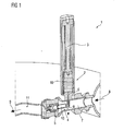
- FIG. 1 is a schematic diagram of an exemplary stroke transmitter 1 for use in a gas turbine.
- the stroke transmitter includes an actuating unit 2 and a valve unit 4.
- the actuating unit 2 and the valve unit 4 are connected to each other through a pipe 6.
- the actuating unit 2 and the valve unit 4 include a hydraulic fluid, which can transfer the pressure generated by the actuating unit 2 to the valve unit 4 through the pipe 6.
- the valve unit 4 is enclosed inside a conduit 7 which provides a passage to a fluid. It may be noted that the temperature of the fluid can be greater than about 140 degrees centigrade.
- the fluid enters the conduit 7 through an inlet 8 and subsequently flows through the valve unit 4 which regulates the flow of the fluid through a dosing valve 5.
- Reference numeral 9 is representative of an outlet of the fluid after passing through the valve unit 4 into a burner (not shown) of the gas turbine.
- the actuating unit 2 is arranged outside the conduit 7. Such an arrangement prevents the actuating unit 2 to be exposed to the fluid path in the conduit 7.
- the valve unit 4 and the actuating unit 2 are arranged at an angle ⁇ relative to each other.
- the angle ⁇ is greater than 0 degrees and less than 180 degrees. More particularly, the angle ⁇ is from about 45 degrees to about 135 degrees.
- valve unit 4 and the actuating unit 2 are arranged such that the valve unit 4 and the actuating unit 2 of the exemplary stroke transmitter 1 are perpendicular to each other.
- the actuating unit 2 includes an actuator 3 for driving a first block 10.
- the first block 10 is filled with a hydraulic fluid, such as, but not limited to hydraulic oil.
- the actuator 3 increases the pressure on the hydraulic fluid in the first block 10.
- the pipe 6 transfers the pressure to the valve unit 4.
- the valve unit 4 includes a second block 15 which causes the dosing valve 5 to open based on the pressure exerted by the hydraulic fluid in the second block 15.
- the actuator 3 is formed from a piezoelectric material.
- the piezoelectric materials include non-conductive materials such as crystals and ceramics.
- One such piezoelectric material is quartz (SiO 2 ).
- the actuator 3 is a piezoelectric actuator. With the help of piezoelectric actuator it is possible in the exemplary stroke transmitter 1 to achieve a quick and precise dosing of large quantities of fluid, in particular of a fuel to a burner (not shown) of the combustion chamber of a gas turbine.
- valve unit 4 of the stroke transmitter 1 is placed axially along an axis of a fluid feed pipe 11 to the burner and the actuating unit 2 is perpendicular to the axis of the fluid feed pipe 11 to the burner.
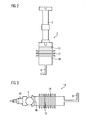
- FIG. 2 is a schematic diagram of the actuating unit 2 of FIG. 1 .
- the actuating unit 2 includes the actuator 3, which, as previously noted is a piezoelectric actuator.
- the actuator 3 is connected to the first block 10.
- a first piston 13 is guided in the first block 10. The actuator 3 causes the first piston 13 to move thereby increasing the pressure in the hydraulic fluid which is filled inside the first block 10.
- the pipe 6 connected to the first block 10 of the actuating unit communicates the pressure of the hydraulic fluid to the valve unit 4.
- the first block 10 is a metallic bellow, which is filled with hydraulic fluid and is connected to the pipe 6.
- the first block 10 includes hollow space which represents a hydraulic volume.
- the first block 10 in the form of the metallic bellow reduces friction and drifting which may be caused when the first block 10 is a metallic cylinder.
- Use of metallic bellow as the first block 10 ensures removal of friction reducing agent, such as grease for example.
- FIG. 3 is a schematic diagram of the valve unit 4 of the stroke transmitter of FIG. 1 .
- the valve unit 4 includes a second block 15.
- the second block 15 may be in a form of cylinder, for example.
- the second block 15 is connected to the pipe 6.
- the pipe 6 communicates pressure from the actuating unit 2 (see FIG. 2 ) to the second block 15, which causes a second piston 16 to move and thereby open a dosing valve 5 of the valve unit 4 to open for allowing dosed feeding of fluid.
- the dosing valve 5 includes a sphere or a needle for opening and closing of the dosing valve 5.
- the second block 15 is a metallic bellow.
- the second block 15 in the form of a metallic bellow ensures that friction and drifting no longer exist, which is generally caused while using metallic cylinders.
- the present arrangement ensures a grease free arrangement of the valve unit 4.
- the valve unit 4 may also includes a sensor 19 which measures the pressure created inside the valve unit 4 and controls the injection of the fuel into the burner not shown in FIG. 3 .
Landscapes
- Engineering & Computer Science (AREA)
- Chemical & Material Sciences (AREA)
- Combustion & Propulsion (AREA)
- Mechanical Engineering (AREA)
- General Engineering & Computer Science (AREA)
- Electrically Driven Valve-Operating Means (AREA)
- Actuator (AREA)
- Fluid-Driven Valves (AREA)
- Fuel-Injection Apparatus (AREA)
Claims (14)
- Transmetteur de course (1), comprenant- un conduit (7) permettant de fournir un passage pour un fluide,- une unité d'actionnement (2) comprenant un premier bloc (10) et un premier piston (13), dans lequel le premier piston (13) est guidé à l'intérieur du premier bloc (10), ce qui augmente une pression d'un fluide hydraulique,- une unité formant soupape (4) comprenant un second bloc (15), une soupape de dosage (5) et un second piston (16), dans lequel le second piston (16) est guidé à l'intérieur du second bloc (15), l'unité formant soupape (4) étant configurée pour fonctionner en fonction de la pression du fluide hydraulique, afin de réguler un écoulement du fluide, et- une canalisation (6) raccordant l'unité d'actionnement (2) et l'unité formant soupape (4) afin de transmettre la pression du fluide hydraulique entre l'unité d'actionnement (2) et l'unité formant soupape (4), dans lequel l'unité formant soupape (4) est agencée à l'intérieur du conduit (7),caractérisé en ce que
l'unité d'actionnement (2) est agencée à l'extérieur du conduit (7). - Transmetteur de course (1) selon la revendication 1, dans lequel l'unité d'actionnement (2) et l'unité formant soupape (4) sont agencées selon un angle l'une par rapport à l'autre.
- Transmetteur de course (1) selon la revendication 2, dans lequel l'angle est compris entre environ 45 degrés et environ 135 degrés.
- Transmetteur de course (1) selon l'une quelconque des revendications 1 à 3, dans lequel l'unité d'actionnement (2) et l'unité formant soupape (4) sont agencées de manière perpendiculaire l'une à l'autre.
- Transmetteur de course (1) selon l'une quelconque des revendications 1 à 4, dans lequel le premier bloc (10) de l'unité d'actionnement (2) est couplé de manière mécanique à un actionneur (3).
- Transmetteur de course (1) selon la revendication 5, dans lequel l'actionneur (3) est un actionneur piézoélectrique.
- Transmetteur de course (1) selon l'une quelconque des revendications 1 à 6, dans lequel le second bloc (15) de l'unité formant soupape (4) est couplé de manière mécanique à la soupape de dosage (5).
- Transmetteur de course (1) selon l'une quelconque des revendications 1 à 7, dans lequel la soupape de dosage (5) comprend une aiguille ou une sphère permettant d'ouvrir et de fermer la soupape de dosage (5).
- Transmetteur de course (1) selon l'une quelconque des revendications 1 à 8, dans lequel le fluide hydraulique comprend de l'huile.
- Transmetteur de course (1) selon l'une quelconque des revendications 1 à 9, dans lequel le premier bloc (10) et/ou le second bloc (15) est/sont de forme cylindrique.
- Transmetteur de course (1) selon l'une quelconque des revendications 1 à 9, dans lequel le premier bloc (10) et/ou le second bloc (15) est/sont un soufflet métallique.
- Turbine à gaz comprenant un transmetteur de course selon l'une quelconque des revendications 1 à 11.
- Turbine à gaz selon la revendication 12, dans laquelle l'unité formant soupape du transmetteur de course est placée de manière axiale le long d'un axe d'une canalisation d'alimentation en fluide (11) conduisant à un dispositif de combustion.
- Turbine à gaz selon la revendication 12 ou 13, dans laquelle l'unité d'actionnement (2) du transmetteur de course (1) est perpendiculaire à un axe d'une canalisation d'alimentation en fluide (11) conduisant à un dispositif de combustion.
Priority Applications (1)
| Application Number | Priority Date | Filing Date | Title |
|---|---|---|---|
| EP20120706599 EP2670964B1 (fr) | 2011-03-16 | 2012-03-01 | Transmetteur de course |
Applications Claiming Priority (3)
| Application Number | Priority Date | Filing Date | Title |
|---|---|---|---|
| EP11158461A EP2500550A1 (fr) | 2011-03-16 | 2011-03-16 | Transmetteur de course pour turbine à gaz |
| PCT/EP2012/053537 WO2012123264A1 (fr) | 2011-03-16 | 2012-03-01 | Émetteur de course pour turbine à gaz |
| EP20120706599 EP2670964B1 (fr) | 2011-03-16 | 2012-03-01 | Transmetteur de course |
Publications (2)
| Publication Number | Publication Date |
|---|---|
| EP2670964A1 EP2670964A1 (fr) | 2013-12-11 |
| EP2670964B1 true EP2670964B1 (fr) | 2015-04-29 |
Family
ID=44245933
Family Applications (2)
| Application Number | Title | Priority Date | Filing Date |
|---|---|---|---|
| EP11158461A Withdrawn EP2500550A1 (fr) | 2011-03-16 | 2011-03-16 | Transmetteur de course pour turbine à gaz |
| EP20120706599 Active EP2670964B1 (fr) | 2011-03-16 | 2012-03-01 | Transmetteur de course |
Family Applications Before (1)
| Application Number | Title | Priority Date | Filing Date |
|---|---|---|---|
| EP11158461A Withdrawn EP2500550A1 (fr) | 2011-03-16 | 2011-03-16 | Transmetteur de course pour turbine à gaz |
Country Status (5)
| Country | Link |
|---|---|
| US (1) | US10156191B2 (fr) |
| EP (2) | EP2500550A1 (fr) |
| CN (1) | CN103459808B (fr) |
| RU (1) | RU2589413C2 (fr) |
| WO (1) | WO2012123264A1 (fr) |
Family Cites Families (18)
| Publication number | Priority date | Publication date | Assignee | Title |
|---|---|---|---|---|
| SU468616A1 (ru) * | 1973-03-30 | 1975-04-30 | Всесоюзное Производственное Проектное Объединения "Союзводпроект" | Автоматический клапан дл закрытой строительной системы |
| US4275558A (en) * | 1977-12-22 | 1981-06-30 | The Garrett Corporation | Gas turbine engine fuel governor |
| DE3115424A1 (de) * | 1981-04-16 | 1982-11-11 | M.A.N. Maschinenfabrik Augsburg-Nürnberg AG, 8500 Nürnberg | Einrichtung zum taktrichtigen betaetigen von gaswechselventilen |
| DE3504639A1 (de) * | 1985-02-11 | 1986-08-14 | INTERATOM GmbH, 5060 Bergisch Gladbach | Hydraulische steuerung fuer ventile von verbrennungskraftmaschinen |
| US4803393A (en) * | 1986-07-31 | 1989-02-07 | Toyota Jidosha Kabushiki Kaisha | Piezoelectric actuator |
| CH681825A5 (fr) * | 1991-05-22 | 1993-05-28 | New Sulzer Diesel Ag | |
| DE4306072C2 (de) * | 1993-02-26 | 1994-12-08 | Siemens Ag | Vorrichtung zum Öffnen und Verschließen einer in einem Gehäuse vorhandenen Durchtrittsöffnung |
| US5549137A (en) | 1993-08-25 | 1996-08-27 | Rosemount Inc. | Valve positioner with pressure feedback, dynamic correction and diagnostics |
| DE4412948C2 (de) * | 1994-04-14 | 1998-07-23 | Siemens Ag | Elektrohydraulische Absperrvorrichtung |
| JPH0861181A (ja) * | 1994-08-25 | 1996-03-05 | Mitsubishi Electric Corp | 燃料噴射装置 |
| DE19709795A1 (de) * | 1997-03-10 | 1998-09-17 | Bosch Gmbh Robert | Kraftstoffeinspritzventil für Brennkraftmaschinen |
| DE29708546U1 (de) * | 1997-05-14 | 1998-09-10 | FEV Motorentechnik GmbH & Co. KG, 52078 Aachen | Elektrischer Festkörperaktuator mit hydraulischer Übersetzung |
| US6570474B2 (en) * | 2000-02-22 | 2003-05-27 | Siemens Automotive Corporation | Magnetostrictive electronic valve timing actuator |
| WO2002036959A2 (fr) * | 2000-11-02 | 2002-05-10 | Siemens Aktiengesellschaft | Dispositif de dosage de liquide comprenant une zone d'etranglement |
| US6725876B2 (en) | 2001-10-15 | 2004-04-27 | Woodward Governor Company | Control valve with integrated electro-hydraulic actuator |
| DE102007053423A1 (de) * | 2007-11-09 | 2009-05-14 | Robert Bosch Gmbh | Piezoelektrisches Aktormodul |
| DE102009015738B4 (de) * | 2009-03-31 | 2016-02-11 | Siemens Aktiengesellschaft | Hydraulischer Hubübersetzer und Injektor zur Dossierung von Fluiden |
| RU99845U1 (ru) * | 2010-05-26 | 2010-11-27 | Общество с ограниченной ответственностью Научно-производственное предприятие "Технопроект" | Клапан с линейным приводом |
-
2011
- 2011-03-16 EP EP11158461A patent/EP2500550A1/fr not_active Withdrawn
-
2012
- 2012-03-01 RU RU2013146094/06A patent/RU2589413C2/ru active
- 2012-03-01 WO PCT/EP2012/053537 patent/WO2012123264A1/fr not_active Ceased
- 2012-03-01 CN CN201280013637.3A patent/CN103459808B/zh active Active
- 2012-03-01 US US14/005,296 patent/US10156191B2/en active Active
- 2012-03-01 EP EP20120706599 patent/EP2670964B1/fr active Active
Also Published As
| Publication number | Publication date |
|---|---|
| CN103459808A (zh) | 2013-12-18 |
| CN103459808B (zh) | 2016-03-30 |
| RU2589413C2 (ru) | 2016-07-10 |
| US20140083104A1 (en) | 2014-03-27 |
| RU2013146094A (ru) | 2015-04-27 |
| US10156191B2 (en) | 2018-12-18 |
| WO2012123264A1 (fr) | 2012-09-20 |
| EP2500550A1 (fr) | 2012-09-19 |
| EP2670964A1 (fr) | 2013-12-11 |
Similar Documents
| Publication | Publication Date | Title |
|---|---|---|
| EP2373910B1 (fr) | Vanne de régulation de fluide | |
| CN106948971B (zh) | 燃料喷射器 | |
| CN101248265B (zh) | 带压电促动器预载的燃料喷射器 | |
| CN101298856B (zh) | 向外打开式燃料喷射器 | |
| KR101815435B1 (ko) | 분사 밸브 용 밸브 어셈블리 및 분사 밸브 | |
| EP2535552B1 (fr) | Ensemble de soupape pour soupape d'injection et soupape d'injection | |
| US8905334B2 (en) | Hydraulic stroke transmitter | |
| CN101331314A (zh) | 燃料喷射器 | |
| KR20190104433A (ko) | 가변 유동 제어를 갖는 직접-구동식 압전 연료 인젝터 | |
| FI117643B (fi) | Järjestely polttoaineen syöttölaitteistossa | |
| CN101415981A (zh) | 包含可调节分隔物的螺线管致动的流控制阀 | |
| EP2670964B1 (fr) | Transmetteur de course | |
| CN101639022B (zh) | 喷射阀 | |
| EP3102882B1 (fr) | Injecteur de carburant avec soupape | |
| US10119426B2 (en) | Slide valve for a waste heat recovery system | |
| US10697373B2 (en) | Active combustion control valve, system and method | |
| US10006429B2 (en) | Variable-area poppet nozzle actuator | |
| CN104421084B (zh) | 流体喷射阀 | |
| US8038079B2 (en) | Injection system and a method for producing an injection system | |
| CN107304742A (zh) | 用于控制介质、尤其是燃料的控制阀 | |
| EP2857671A1 (fr) | Injecteur de fluide | |
| US7063278B2 (en) | Fuel injection valve | |
| US20140131466A1 (en) | Hydraulic displacement amplifiers for fuel injectors | |
| WO2013187961A1 (fr) | Manifold de distribution de flux | |
| EP2075857B1 (fr) | Agencement d'actionneur et soupape à injection |
Legal Events
| Date | Code | Title | Description |
|---|---|---|---|
| PUAI | Public reference made under article 153(3) epc to a published international application that has entered the european phase |
Free format text: ORIGINAL CODE: 0009012 |
|
| 17P | Request for examination filed |
Effective date: 20130902 |
|
| AK | Designated contracting states |
Kind code of ref document: A1 Designated state(s): AL AT BE BG CH CY CZ DE DK EE ES FI FR GB GR HR HU IE IS IT LI LT LU LV MC MK MT NL NO PL PT RO RS SE SI SK SM TR |
|
| DAX | Request for extension of the european patent (deleted) | ||
| GRAP | Despatch of communication of intention to grant a patent |
Free format text: ORIGINAL CODE: EPIDOSNIGR1 |
|
| INTG | Intention to grant announced |
Effective date: 20141017 |
|
| GRAS | Grant fee paid |
Free format text: ORIGINAL CODE: EPIDOSNIGR3 |
|
| GRAA | (expected) grant |
Free format text: ORIGINAL CODE: 0009210 |
|
| AK | Designated contracting states |
Kind code of ref document: B1 Designated state(s): AL AT BE BG CH CY CZ DE DK EE ES FI FR GB GR HR HU IE IS IT LI LT LU LV MC MK MT NL NO PL PT RO RS SE SI SK SM TR |
|
| REG | Reference to a national code |
Ref country code: GB Ref legal event code: FG4D |
|
| REG | Reference to a national code |
Ref country code: CH Ref legal event code: EP |
|
| REG | Reference to a national code |
Ref country code: AT Ref legal event code: REF Ref document number: 724577 Country of ref document: AT Kind code of ref document: T Effective date: 20150515 |
|
| REG | Reference to a national code |
Ref country code: IE Ref legal event code: FG4D |
|
| REG | Reference to a national code |
Ref country code: DE Ref legal event code: R096 Ref document number: 602012006995 Country of ref document: DE Effective date: 20150611 |
|
| REG | Reference to a national code |
Ref country code: SE Ref legal event code: TRGR |
|
| REG | Reference to a national code |
Ref country code: NL Ref legal event code: VDEP Effective date: 20150429 |
|
| REG | Reference to a national code |
Ref country code: AT Ref legal event code: MK05 Ref document number: 724577 Country of ref document: AT Kind code of ref document: T Effective date: 20150429 |
|
| REG | Reference to a national code |
Ref country code: LT Ref legal event code: MG4D |
|
| PG25 | Lapsed in a contracting state [announced via postgrant information from national office to epo] |
Ref country code: NL Free format text: LAPSE BECAUSE OF FAILURE TO SUBMIT A TRANSLATION OF THE DESCRIPTION OR TO PAY THE FEE WITHIN THE PRESCRIBED TIME-LIMIT Effective date: 20150429 |
|
| PG25 | Lapsed in a contracting state [announced via postgrant information from national office to epo] |
Ref country code: PT Free format text: LAPSE BECAUSE OF FAILURE TO SUBMIT A TRANSLATION OF THE DESCRIPTION OR TO PAY THE FEE WITHIN THE PRESCRIBED TIME-LIMIT Effective date: 20150831 Ref country code: NO Free format text: LAPSE BECAUSE OF FAILURE TO SUBMIT A TRANSLATION OF THE DESCRIPTION OR TO PAY THE FEE WITHIN THE PRESCRIBED TIME-LIMIT Effective date: 20150729 Ref country code: HR Free format text: LAPSE BECAUSE OF FAILURE TO SUBMIT A TRANSLATION OF THE DESCRIPTION OR TO PAY THE FEE WITHIN THE PRESCRIBED TIME-LIMIT Effective date: 20150429 Ref country code: LT Free format text: LAPSE BECAUSE OF FAILURE TO SUBMIT A TRANSLATION OF THE DESCRIPTION OR TO PAY THE FEE WITHIN THE PRESCRIBED TIME-LIMIT Effective date: 20150429 Ref country code: ES Free format text: LAPSE BECAUSE OF FAILURE TO SUBMIT A TRANSLATION OF THE DESCRIPTION OR TO PAY THE FEE WITHIN THE PRESCRIBED TIME-LIMIT Effective date: 20150429 Ref country code: FI Free format text: LAPSE BECAUSE OF FAILURE TO SUBMIT A TRANSLATION OF THE DESCRIPTION OR TO PAY THE FEE WITHIN THE PRESCRIBED TIME-LIMIT Effective date: 20150429 |
|
| PG25 | Lapsed in a contracting state [announced via postgrant information from national office to epo] |
Ref country code: GR Free format text: LAPSE BECAUSE OF FAILURE TO SUBMIT A TRANSLATION OF THE DESCRIPTION OR TO PAY THE FEE WITHIN THE PRESCRIBED TIME-LIMIT Effective date: 20150730 Ref country code: AT Free format text: LAPSE BECAUSE OF FAILURE TO SUBMIT A TRANSLATION OF THE DESCRIPTION OR TO PAY THE FEE WITHIN THE PRESCRIBED TIME-LIMIT Effective date: 20150429 Ref country code: IS Free format text: LAPSE BECAUSE OF FAILURE TO SUBMIT A TRANSLATION OF THE DESCRIPTION OR TO PAY THE FEE WITHIN THE PRESCRIBED TIME-LIMIT Effective date: 20150829 Ref country code: RS Free format text: LAPSE BECAUSE OF FAILURE TO SUBMIT A TRANSLATION OF THE DESCRIPTION OR TO PAY THE FEE WITHIN THE PRESCRIBED TIME-LIMIT Effective date: 20150429 Ref country code: LV Free format text: LAPSE BECAUSE OF FAILURE TO SUBMIT A TRANSLATION OF THE DESCRIPTION OR TO PAY THE FEE WITHIN THE PRESCRIBED TIME-LIMIT Effective date: 20150429 |
|
| PG25 | Lapsed in a contracting state [announced via postgrant information from national office to epo] |
Ref country code: DK Free format text: LAPSE BECAUSE OF FAILURE TO SUBMIT A TRANSLATION OF THE DESCRIPTION OR TO PAY THE FEE WITHIN THE PRESCRIBED TIME-LIMIT Effective date: 20150429 Ref country code: EE Free format text: LAPSE BECAUSE OF FAILURE TO SUBMIT A TRANSLATION OF THE DESCRIPTION OR TO PAY THE FEE WITHIN THE PRESCRIBED TIME-LIMIT Effective date: 20150429 |
|
| REG | Reference to a national code |
Ref country code: DE Ref legal event code: R097 Ref document number: 602012006995 Country of ref document: DE |
|
| PG25 | Lapsed in a contracting state [announced via postgrant information from national office to epo] |
Ref country code: SK Free format text: LAPSE BECAUSE OF FAILURE TO SUBMIT A TRANSLATION OF THE DESCRIPTION OR TO PAY THE FEE WITHIN THE PRESCRIBED TIME-LIMIT Effective date: 20150429 Ref country code: RO Free format text: LAPSE BECAUSE OF NON-PAYMENT OF DUE FEES Effective date: 20150429 Ref country code: PL Free format text: LAPSE BECAUSE OF FAILURE TO SUBMIT A TRANSLATION OF THE DESCRIPTION OR TO PAY THE FEE WITHIN THE PRESCRIBED TIME-LIMIT Effective date: 20150429 Ref country code: CZ Free format text: LAPSE BECAUSE OF FAILURE TO SUBMIT A TRANSLATION OF THE DESCRIPTION OR TO PAY THE FEE WITHIN THE PRESCRIBED TIME-LIMIT Effective date: 20150429 |
|
| PLBE | No opposition filed within time limit |
Free format text: ORIGINAL CODE: 0009261 |
|
| STAA | Information on the status of an ep patent application or granted ep patent |
Free format text: STATUS: NO OPPOSITION FILED WITHIN TIME LIMIT |
|
| REG | Reference to a national code |
Ref country code: FR Ref legal event code: PLFP Year of fee payment: 5 |
|
| 26N | No opposition filed |
Effective date: 20160201 |
|
| PG25 | Lapsed in a contracting state [announced via postgrant information from national office to epo] |
Ref country code: SI Free format text: LAPSE BECAUSE OF FAILURE TO SUBMIT A TRANSLATION OF THE DESCRIPTION OR TO PAY THE FEE WITHIN THE PRESCRIBED TIME-LIMIT Effective date: 20150429 |
|
| PG25 | Lapsed in a contracting state [announced via postgrant information from national office to epo] |
Ref country code: BE Free format text: LAPSE BECAUSE OF FAILURE TO SUBMIT A TRANSLATION OF THE DESCRIPTION OR TO PAY THE FEE WITHIN THE PRESCRIBED TIME-LIMIT Effective date: 20150429 |
|
| PG25 | Lapsed in a contracting state [announced via postgrant information from national office to epo] |
Ref country code: MC Free format text: LAPSE BECAUSE OF FAILURE TO SUBMIT A TRANSLATION OF THE DESCRIPTION OR TO PAY THE FEE WITHIN THE PRESCRIBED TIME-LIMIT Effective date: 20150429 Ref country code: LU Free format text: LAPSE BECAUSE OF FAILURE TO SUBMIT A TRANSLATION OF THE DESCRIPTION OR TO PAY THE FEE WITHIN THE PRESCRIBED TIME-LIMIT Effective date: 20160301 |
|
| REG | Reference to a national code |
Ref country code: CH Ref legal event code: PL |
|
| REG | Reference to a national code |
Ref country code: IE Ref legal event code: MM4A |
|
| PG25 | Lapsed in a contracting state [announced via postgrant information from national office to epo] |
Ref country code: IE Free format text: LAPSE BECAUSE OF NON-PAYMENT OF DUE FEES Effective date: 20160301 Ref country code: CH Free format text: LAPSE BECAUSE OF NON-PAYMENT OF DUE FEES Effective date: 20160331 Ref country code: LI Free format text: LAPSE BECAUSE OF NON-PAYMENT OF DUE FEES Effective date: 20160331 |
|
| REG | Reference to a national code |
Ref country code: FR Ref legal event code: PLFP Year of fee payment: 6 |
|
| PG25 | Lapsed in a contracting state [announced via postgrant information from national office to epo] |
Ref country code: MT Free format text: LAPSE BECAUSE OF FAILURE TO SUBMIT A TRANSLATION OF THE DESCRIPTION OR TO PAY THE FEE WITHIN THE PRESCRIBED TIME-LIMIT Effective date: 20150429 |
|
| REG | Reference to a national code |
Ref country code: FR Ref legal event code: PLFP Year of fee payment: 7 |
|
| PG25 | Lapsed in a contracting state [announced via postgrant information from national office to epo] |
Ref country code: CY Free format text: LAPSE BECAUSE OF FAILURE TO SUBMIT A TRANSLATION OF THE DESCRIPTION OR TO PAY THE FEE WITHIN THE PRESCRIBED TIME-LIMIT Effective date: 20150429 Ref country code: SM Free format text: LAPSE BECAUSE OF FAILURE TO SUBMIT A TRANSLATION OF THE DESCRIPTION OR TO PAY THE FEE WITHIN THE PRESCRIBED TIME-LIMIT Effective date: 20150429 Ref country code: HU Free format text: LAPSE BECAUSE OF FAILURE TO SUBMIT A TRANSLATION OF THE DESCRIPTION OR TO PAY THE FEE WITHIN THE PRESCRIBED TIME-LIMIT; INVALID AB INITIO Effective date: 20120301 |
|
| PG25 | Lapsed in a contracting state [announced via postgrant information from national office to epo] |
Ref country code: TR Free format text: LAPSE BECAUSE OF FAILURE TO SUBMIT A TRANSLATION OF THE DESCRIPTION OR TO PAY THE FEE WITHIN THE PRESCRIBED TIME-LIMIT Effective date: 20150429 Ref country code: MK Free format text: LAPSE BECAUSE OF FAILURE TO SUBMIT A TRANSLATION OF THE DESCRIPTION OR TO PAY THE FEE WITHIN THE PRESCRIBED TIME-LIMIT Effective date: 20150429 Ref country code: MT Free format text: LAPSE BECAUSE OF FAILURE TO SUBMIT A TRANSLATION OF THE DESCRIPTION OR TO PAY THE FEE WITHIN THE PRESCRIBED TIME-LIMIT Effective date: 20160331 |
|
| PG25 | Lapsed in a contracting state [announced via postgrant information from national office to epo] |
Ref country code: BG Free format text: LAPSE BECAUSE OF FAILURE TO SUBMIT A TRANSLATION OF THE DESCRIPTION OR TO PAY THE FEE WITHIN THE PRESCRIBED TIME-LIMIT Effective date: 20150429 |
|
| PG25 | Lapsed in a contracting state [announced via postgrant information from national office to epo] |
Ref country code: AL Free format text: LAPSE BECAUSE OF FAILURE TO SUBMIT A TRANSLATION OF THE DESCRIPTION OR TO PAY THE FEE WITHIN THE PRESCRIBED TIME-LIMIT Effective date: 20150429 |
|
| REG | Reference to a national code |
Ref country code: DE Ref legal event code: R081 Ref document number: 602012006995 Country of ref document: DE Owner name: METISMOTION GMBH, DE Free format text: FORMER OWNER: SIEMENS AKTIENGESELLSCHAFT, 80333 MUENCHEN, DE |
|
| REG | Reference to a national code |
Ref country code: GB Ref legal event code: 732E Free format text: REGISTERED BETWEEN 20200618 AND 20200624 |
|
| PGFP | Annual fee paid to national office [announced via postgrant information from national office to epo] |
Ref country code: SE Payment date: 20250311 Year of fee payment: 14 |
|
| PGFP | Annual fee paid to national office [announced via postgrant information from national office to epo] |
Ref country code: IT Payment date: 20250331 Year of fee payment: 14 |
|
| PGFP | Annual fee paid to national office [announced via postgrant information from national office to epo] |
Ref country code: GB Payment date: 20260324 Year of fee payment: 15 |
|
| PGFP | Annual fee paid to national office [announced via postgrant information from national office to epo] |
Ref country code: DE Payment date: 20260325 Year of fee payment: 15 |
|
| PGFP | Annual fee paid to national office [announced via postgrant information from national office to epo] |
Ref country code: FR Payment date: 20260325 Year of fee payment: 15 |