EP2672085A1 - Dispositif de brûleur pour augmentation de la température des gaz d'échappement - Google Patents
Dispositif de brûleur pour augmentation de la température des gaz d'échappement Download PDFInfo
- Publication number
- EP2672085A1 EP2672085A1 EP11857868.1A EP11857868A EP2672085A1 EP 2672085 A1 EP2672085 A1 EP 2672085A1 EP 11857868 A EP11857868 A EP 11857868A EP 2672085 A1 EP2672085 A1 EP 2672085A1
- Authority
- EP
- European Patent Office
- Prior art keywords
- exhaust pipe
- support member
- burner
- shaped
- catalyst
- Prior art date
- Legal status (The legal status is an assumption and is not a legal conclusion. Google has not performed a legal analysis and makes no representation as to the accuracy of the status listed.)
- Withdrawn
Links
Images


Classifications
-
- F—MECHANICAL ENGINEERING; LIGHTING; HEATING; WEAPONS; BLASTING
- F01—MACHINES OR ENGINES IN GENERAL; ENGINE PLANTS IN GENERAL; STEAM ENGINES
- F01N—GAS-FLOW SILENCERS OR EXHAUST APPARATUS FOR MACHINES OR ENGINES IN GENERAL; GAS-FLOW SILENCERS OR EXHAUST APPARATUS FOR INTERNAL-COMBUSTION ENGINES
- F01N3/00—Exhaust or silencing apparatus having means for purifying, rendering innocuous, or otherwise treating exhaust
- F01N3/02—Exhaust or silencing apparatus having means for purifying, rendering innocuous, or otherwise treating exhaust for cooling, or for removing solid constituents of, exhaust
- F01N3/021—Exhaust or silencing apparatus having means for purifying, rendering innocuous, or otherwise treating exhaust for cooling, or for removing solid constituents of, exhaust by means of filters
- F01N3/023—Exhaust or silencing apparatus having means for purifying, rendering innocuous, or otherwise treating exhaust for cooling, or for removing solid constituents of, exhaust by means of filters using means for regenerating the filters, e.g. by burning trapped particles
- F01N3/025—Exhaust or silencing apparatus having means for purifying, rendering innocuous, or otherwise treating exhaust for cooling, or for removing solid constituents of, exhaust by means of filters using means for regenerating the filters, e.g. by burning trapped particles using fuel burner or by adding fuel to exhaust
- F01N3/0253—Exhaust or silencing apparatus having means for purifying, rendering innocuous, or otherwise treating exhaust for cooling, or for removing solid constituents of, exhaust by means of filters using means for regenerating the filters, e.g. by burning trapped particles using fuel burner or by adding fuel to exhaust adding fuel to exhaust gases
- F01N3/0256—Exhaust or silencing apparatus having means for purifying, rendering innocuous, or otherwise treating exhaust for cooling, or for removing solid constituents of, exhaust by means of filters using means for regenerating the filters, e.g. by burning trapped particles using fuel burner or by adding fuel to exhaust adding fuel to exhaust gases the fuel being ignited by electrical means
-
- F—MECHANICAL ENGINEERING; LIGHTING; HEATING; WEAPONS; BLASTING
- F01—MACHINES OR ENGINES IN GENERAL; ENGINE PLANTS IN GENERAL; STEAM ENGINES
- F01N—GAS-FLOW SILENCERS OR EXHAUST APPARATUS FOR MACHINES OR ENGINES IN GENERAL; GAS-FLOW SILENCERS OR EXHAUST APPARATUS FOR INTERNAL-COMBUSTION ENGINES
- F01N3/00—Exhaust or silencing apparatus having means for purifying, rendering innocuous, or otherwise treating exhaust
- F01N3/02—Exhaust or silencing apparatus having means for purifying, rendering innocuous, or otherwise treating exhaust for cooling, or for removing solid constituents of, exhaust
- F01N3/021—Exhaust or silencing apparatus having means for purifying, rendering innocuous, or otherwise treating exhaust for cooling, or for removing solid constituents of, exhaust by means of filters
- F01N3/023—Exhaust or silencing apparatus having means for purifying, rendering innocuous, or otherwise treating exhaust for cooling, or for removing solid constituents of, exhaust by means of filters using means for regenerating the filters, e.g. by burning trapped particles
- F01N3/025—Exhaust or silencing apparatus having means for purifying, rendering innocuous, or otherwise treating exhaust for cooling, or for removing solid constituents of, exhaust by means of filters using means for regenerating the filters, e.g. by burning trapped particles using fuel burner or by adding fuel to exhaust
-
- F—MECHANICAL ENGINEERING; LIGHTING; HEATING; WEAPONS; BLASTING
- F01—MACHINES OR ENGINES IN GENERAL; ENGINE PLANTS IN GENERAL; STEAM ENGINES
- F01N—GAS-FLOW SILENCERS OR EXHAUST APPARATUS FOR MACHINES OR ENGINES IN GENERAL; GAS-FLOW SILENCERS OR EXHAUST APPARATUS FOR INTERNAL-COMBUSTION ENGINES
- F01N3/00—Exhaust or silencing apparatus having means for purifying, rendering innocuous, or otherwise treating exhaust
- F01N3/08—Exhaust or silencing apparatus having means for purifying, rendering innocuous, or otherwise treating exhaust for rendering innocuous
- F01N3/0807—Exhaust or silencing apparatus having means for purifying, rendering innocuous, or otherwise treating exhaust for rendering innocuous by using absorbents or adsorbents
- F01N3/0828—Exhaust or silencing apparatus having means for purifying, rendering innocuous, or otherwise treating exhaust for rendering innocuous by using absorbents or adsorbents characterised by the absorbed or adsorbed substances
- F01N3/0842—Nitrogen oxides
-
- F—MECHANICAL ENGINEERING; LIGHTING; HEATING; WEAPONS; BLASTING
- F01—MACHINES OR ENGINES IN GENERAL; ENGINE PLANTS IN GENERAL; STEAM ENGINES
- F01N—GAS-FLOW SILENCERS OR EXHAUST APPARATUS FOR MACHINES OR ENGINES IN GENERAL; GAS-FLOW SILENCERS OR EXHAUST APPARATUS FOR INTERNAL-COMBUSTION ENGINES
- F01N3/00—Exhaust or silencing apparatus having means for purifying, rendering innocuous, or otherwise treating exhaust
- F01N3/08—Exhaust or silencing apparatus having means for purifying, rendering innocuous, or otherwise treating exhaust for rendering innocuous
- F01N3/10—Exhaust or silencing apparatus having means for purifying, rendering innocuous, or otherwise treating exhaust for rendering innocuous by thermal or catalytic conversion of noxious components of exhaust
- F01N3/103—Oxidation catalysts for HC and CO only
-
- F—MECHANICAL ENGINEERING; LIGHTING; HEATING; WEAPONS; BLASTING
- F01—MACHINES OR ENGINES IN GENERAL; ENGINE PLANTS IN GENERAL; STEAM ENGINES
- F01N—GAS-FLOW SILENCERS OR EXHAUST APPARATUS FOR MACHINES OR ENGINES IN GENERAL; GAS-FLOW SILENCERS OR EXHAUST APPARATUS FOR INTERNAL-COMBUSTION ENGINES
- F01N3/00—Exhaust or silencing apparatus having means for purifying, rendering innocuous, or otherwise treating exhaust
- F01N3/08—Exhaust or silencing apparatus having means for purifying, rendering innocuous, or otherwise treating exhaust for rendering innocuous
- F01N3/10—Exhaust or silencing apparatus having means for purifying, rendering innocuous, or otherwise treating exhaust for rendering innocuous by thermal or catalytic conversion of noxious components of exhaust
- F01N3/105—General auxiliary catalysts, e.g. upstream or downstream of the main catalyst
- F01N3/106—Auxiliary oxidation catalysts
-
- F—MECHANICAL ENGINEERING; LIGHTING; HEATING; WEAPONS; BLASTING
- F01—MACHINES OR ENGINES IN GENERAL; ENGINE PLANTS IN GENERAL; STEAM ENGINES
- F01N—GAS-FLOW SILENCERS OR EXHAUST APPARATUS FOR MACHINES OR ENGINES IN GENERAL; GAS-FLOW SILENCERS OR EXHAUST APPARATUS FOR INTERNAL-COMBUSTION ENGINES
- F01N3/00—Exhaust or silencing apparatus having means for purifying, rendering innocuous, or otherwise treating exhaust
- F01N3/08—Exhaust or silencing apparatus having means for purifying, rendering innocuous, or otherwise treating exhaust for rendering innocuous
- F01N3/10—Exhaust or silencing apparatus having means for purifying, rendering innocuous, or otherwise treating exhaust for rendering innocuous by thermal or catalytic conversion of noxious components of exhaust
- F01N3/18—Exhaust or silencing apparatus having means for purifying, rendering innocuous, or otherwise treating exhaust for rendering innocuous by thermal or catalytic conversion of noxious components of exhaust characterised by methods of operation; Control
- F01N3/20—Exhaust or silencing apparatus having means for purifying, rendering innocuous, or otherwise treating exhaust for rendering innocuous by thermal or catalytic conversion of noxious components of exhaust characterised by methods of operation; Control specially adapted for catalytic conversion
- F01N3/2006—Periodically heating or cooling catalytic reactors, e.g. at cold starting or overheating
- F01N3/2033—Periodically heating or cooling catalytic reactors, e.g. at cold starting or overheating using a fuel burner or introducing fuel into exhaust duct
-
- F—MECHANICAL ENGINEERING; LIGHTING; HEATING; WEAPONS; BLASTING
- F01—MACHINES OR ENGINES IN GENERAL; ENGINE PLANTS IN GENERAL; STEAM ENGINES
- F01N—GAS-FLOW SILENCERS OR EXHAUST APPARATUS FOR MACHINES OR ENGINES IN GENERAL; GAS-FLOW SILENCERS OR EXHAUST APPARATUS FOR INTERNAL-COMBUSTION ENGINES
- F01N3/00—Exhaust or silencing apparatus having means for purifying, rendering innocuous, or otherwise treating exhaust
- F01N3/08—Exhaust or silencing apparatus having means for purifying, rendering innocuous, or otherwise treating exhaust for rendering innocuous
- F01N3/10—Exhaust or silencing apparatus having means for purifying, rendering innocuous, or otherwise treating exhaust for rendering innocuous by thermal or catalytic conversion of noxious components of exhaust
- F01N3/24—Exhaust or silencing apparatus having means for purifying, rendering innocuous, or otherwise treating exhaust for rendering innocuous by thermal or catalytic conversion of noxious components of exhaust characterised by constructional aspects of converting apparatus
- F01N3/28—Construction of catalytic reactors
- F01N3/2839—Arrangements for mounting catalyst support in housing, e.g. with means for compensating thermal expansion or vibration
- F01N3/2853—Arrangements for mounting catalyst support in housing, e.g. with means for compensating thermal expansion or vibration using mats or gaskets between catalyst body and housing
-
- F—MECHANICAL ENGINEERING; LIGHTING; HEATING; WEAPONS; BLASTING
- F01—MACHINES OR ENGINES IN GENERAL; ENGINE PLANTS IN GENERAL; STEAM ENGINES
- F01N—GAS-FLOW SILENCERS OR EXHAUST APPARATUS FOR MACHINES OR ENGINES IN GENERAL; GAS-FLOW SILENCERS OR EXHAUST APPARATUS FOR INTERNAL-COMBUSTION ENGINES
- F01N3/00—Exhaust or silencing apparatus having means for purifying, rendering innocuous, or otherwise treating exhaust
- F01N3/08—Exhaust or silencing apparatus having means for purifying, rendering innocuous, or otherwise treating exhaust for rendering innocuous
- F01N3/10—Exhaust or silencing apparatus having means for purifying, rendering innocuous, or otherwise treating exhaust for rendering innocuous by thermal or catalytic conversion of noxious components of exhaust
- F01N3/24—Exhaust or silencing apparatus having means for purifying, rendering innocuous, or otherwise treating exhaust for rendering innocuous by thermal or catalytic conversion of noxious components of exhaust characterised by constructional aspects of converting apparatus
- F01N3/28—Construction of catalytic reactors
- F01N3/2839—Arrangements for mounting catalyst support in housing, e.g. with means for compensating thermal expansion or vibration
- F01N3/2875—Arrangements for mounting catalyst support in housing, e.g. with means for compensating thermal expansion or vibration by using elastic means, e.g. spring leaves, for retaining catalyst body in the housing
-
- F—MECHANICAL ENGINEERING; LIGHTING; HEATING; WEAPONS; BLASTING
- F01—MACHINES OR ENGINES IN GENERAL; ENGINE PLANTS IN GENERAL; STEAM ENGINES
- F01N—GAS-FLOW SILENCERS OR EXHAUST APPARATUS FOR MACHINES OR ENGINES IN GENERAL; GAS-FLOW SILENCERS OR EXHAUST APPARATUS FOR INTERNAL-COMBUSTION ENGINES
- F01N3/00—Exhaust or silencing apparatus having means for purifying, rendering innocuous, or otherwise treating exhaust
- F01N3/08—Exhaust or silencing apparatus having means for purifying, rendering innocuous, or otherwise treating exhaust for rendering innocuous
- F01N3/10—Exhaust or silencing apparatus having means for purifying, rendering innocuous, or otherwise treating exhaust for rendering innocuous by thermal or catalytic conversion of noxious components of exhaust
- F01N3/24—Exhaust or silencing apparatus having means for purifying, rendering innocuous, or otherwise treating exhaust for rendering innocuous by thermal or catalytic conversion of noxious components of exhaust characterised by constructional aspects of converting apparatus
- F01N3/36—Arrangements for supply of additional fuel
-
- F—MECHANICAL ENGINEERING; LIGHTING; HEATING; WEAPONS; BLASTING
- F01—MACHINES OR ENGINES IN GENERAL; ENGINE PLANTS IN GENERAL; STEAM ENGINES
- F01N—GAS-FLOW SILENCERS OR EXHAUST APPARATUS FOR MACHINES OR ENGINES IN GENERAL; GAS-FLOW SILENCERS OR EXHAUST APPARATUS FOR INTERNAL-COMBUSTION ENGINES
- F01N3/00—Exhaust or silencing apparatus having means for purifying, rendering innocuous, or otherwise treating exhaust
- F01N3/08—Exhaust or silencing apparatus having means for purifying, rendering innocuous, or otherwise treating exhaust for rendering innocuous
- F01N3/10—Exhaust or silencing apparatus having means for purifying, rendering innocuous, or otherwise treating exhaust for rendering innocuous by thermal or catalytic conversion of noxious components of exhaust
- F01N3/24—Exhaust or silencing apparatus having means for purifying, rendering innocuous, or otherwise treating exhaust for rendering innocuous by thermal or catalytic conversion of noxious components of exhaust characterised by constructional aspects of converting apparatus
- F01N3/38—Arrangements for igniting
-
- F—MECHANICAL ENGINEERING; LIGHTING; HEATING; WEAPONS; BLASTING
- F01—MACHINES OR ENGINES IN GENERAL; ENGINE PLANTS IN GENERAL; STEAM ENGINES
- F01N—GAS-FLOW SILENCERS OR EXHAUST APPARATUS FOR MACHINES OR ENGINES IN GENERAL; GAS-FLOW SILENCERS OR EXHAUST APPARATUS FOR INTERNAL-COMBUSTION ENGINES
- F01N2240/00—Combination or association of two or more different exhaust treating devices, or of at least one such device with an auxiliary device, not covered by indexing codes F01N2230/00 or F01N2250/00, one of the devices being
- F01N2240/14—Combination or association of two or more different exhaust treating devices, or of at least one such device with an auxiliary device, not covered by indexing codes F01N2230/00 or F01N2250/00, one of the devices being a fuel burner
-
- F—MECHANICAL ENGINEERING; LIGHTING; HEATING; WEAPONS; BLASTING
- F01—MACHINES OR ENGINES IN GENERAL; ENGINE PLANTS IN GENERAL; STEAM ENGINES
- F01N—GAS-FLOW SILENCERS OR EXHAUST APPARATUS FOR MACHINES OR ENGINES IN GENERAL; GAS-FLOW SILENCERS OR EXHAUST APPARATUS FOR INTERNAL-COMBUSTION ENGINES
- F01N2240/00—Combination or association of two or more different exhaust treating devices, or of at least one such device with an auxiliary device, not covered by indexing codes F01N2230/00 or F01N2250/00, one of the devices being
- F01N2240/20—Combination or association of two or more different exhaust treating devices, or of at least one such device with an auxiliary device, not covered by indexing codes F01N2230/00 or F01N2250/00, one of the devices being a flow director or deflector
-
- F—MECHANICAL ENGINEERING; LIGHTING; HEATING; WEAPONS; BLASTING
- F01—MACHINES OR ENGINES IN GENERAL; ENGINE PLANTS IN GENERAL; STEAM ENGINES
- F01N—GAS-FLOW SILENCERS OR EXHAUST APPARATUS FOR MACHINES OR ENGINES IN GENERAL; GAS-FLOW SILENCERS OR EXHAUST APPARATUS FOR INTERNAL-COMBUSTION ENGINES
- F01N2260/00—Exhaust treating devices having provisions not otherwise provided for
- F01N2260/10—Exhaust treating devices having provisions not otherwise provided for for avoiding stress caused by expansions or contractions due to temperature variations
-
- F—MECHANICAL ENGINEERING; LIGHTING; HEATING; WEAPONS; BLASTING
- F01—MACHINES OR ENGINES IN GENERAL; ENGINE PLANTS IN GENERAL; STEAM ENGINES
- F01N—GAS-FLOW SILENCERS OR EXHAUST APPARATUS FOR MACHINES OR ENGINES IN GENERAL; GAS-FLOW SILENCERS OR EXHAUST APPARATUS FOR INTERNAL-COMBUSTION ENGINES
- F01N2610/00—Adding substances to exhaust gases
- F01N2610/14—Arrangements for the supply of substances, e.g. conduits
- F01N2610/1453—Sprayers or atomisers; Arrangement thereof in the exhaust apparatus
-
- Y—GENERAL TAGGING OF NEW TECHNOLOGICAL DEVELOPMENTS; GENERAL TAGGING OF CROSS-SECTIONAL TECHNOLOGIES SPANNING OVER SEVERAL SECTIONS OF THE IPC; TECHNICAL SUBJECTS COVERED BY FORMER USPC CROSS-REFERENCE ART COLLECTIONS [XRACs] AND DIGESTS
- Y02—TECHNOLOGIES OR APPLICATIONS FOR MITIGATION OR ADAPTATION AGAINST CLIMATE CHANGE
- Y02T—CLIMATE CHANGE MITIGATION TECHNOLOGIES RELATED TO TRANSPORTATION
- Y02T10/00—Road transport of goods or passengers
- Y02T10/10—Internal combustion engine [ICE] based vehicles
- Y02T10/12—Improving ICE efficiencies
Definitions
- This invention relates to a burner device and, more particularly, to a burner device provided upstream of an exhaust treatment device in an exhaust gas passage of an internal combustion engine to increase a temperature of an exhaust gas.
- the burner device described in Patent Literature 1 includes a small-sized oxidation catalyst (hereinafter referred to as "burner catalyst") placed upstream of the exhaust treatment device, having a cross-sectional area smaller than that of the exhaust gas passage of the engine and allowing a portion of the exhaust gas to flow in the burner catalyst, fuel supply means that supplies fuel to the burner catalyst in the exhaust gas passage, and ignition means that ignites and burns the supplied fuel.
- burner catalyst small-sized oxidation catalyst
- the burner device cited in the PTL 1 is structured to hold the burner catalyst having a cross-sectional area smaller than that of the exhaust gas passage in an exhaust pipe forming part of the exhaust gas passage, and uses a plurality of plate-shaped stays extending radially. Then, the axially upstream and downstream end regions in the inner-diameter ends of the plate-shaped stays are welded to the outer surface of the cylindrical outer frame of the burner catalyst, and the axially upstream and downstream end regions in the outer-diameter ends thereof are welded to the inner surface of the exhaust pipe.
- the use of the plate-shaped stays having both ends welded in this manner involves a great difference in thermal expansion between the exhaust pipe exposed to the relatively-low-temperature atmosphere and, the burner catalyst and the cylindrical outer frame (casing) of the burner catalyst which are exposed to the high-temperature combustion gas, so that it is difficult to absorb the difference in thermal expansion not only in the axial direction of the burner device but also in the radial direction.
- thermal stress repeatedly occurs in the portions welded (joined) to the plate-shaped stays, which may possibly cause a reduction in durability of the burner device.
- the operation processes of welding the axially upstream and downstream end regions in the inner-diameter ends of the plate-shaped stays to the outer surface of the cylindrical outer frame of the burner catalyst and, in particular, of welding the axially upstream and downstream end regions in the outer-diameter ends to the inner surface of the exhaust pipe are complicated, thus making the manufacture hard and being unfitted for mass production.
- a burner device placed upstream of an exhaust treatment device mounted in an exhaust pipe to raise a temperature of an exhaust gas, comprising: a fuel supply valve for supplying fuel into the exhaust pipe; an igniter that ignites the fuel supplied from the fuel supply valve; and a burner catalyst held in the exhaust pipe through a support member, wherein the support member is formed in a corrugated shape in cross section including outer arc-shaped portions in contact with the exhaust pipe, inner arc-shaped portions in contact with an outer peripheral member of the burner catalyst, and coupling portions for coupling the outer arc-shaped portions and the inner arc-shaped portions to each other.
- the burner device when the fuel supplied from the fuel supply valve is ignited by the igniter, the burning flame passes in the burner catalyst held in the exhaust pipe through the support member, and also passes in the passage between the burner catalyst and the exhaust pipe.
- the differences in thermal expansion in the axial direction and the radial direction of the burner device are absorbed by the support member formed in a corrugated shape in cross section.
- the support stiffness of the burner catalyst in the burner device can be ensured to increase the durability.
- each of angles formed by each of the outer arc-shaped portions and each of the coupling portions, and by each of the inner arc-shaped portions and each of the coupling portions in a plane orthogonal to an axis of the exhaust pipe is preferably an obtuse angle.
- each of passages formed between the exhaust pipe and the support member and between the support member and the outer peripheral member of the burner catalyst is not formed in parallel to the axis of the exhaust pipe, but is preferably formed in a twist manner.
- the exhaust pipe may include a separate ring-shaped member on an inner periphery of the exhaust pipe.
- a cushioning mat may be inserted between the ring-shaped member and the exhaust pipe.
- the outer arc-shaped portions of the support member may be in contact with the ring-shaped member.
- the burner device may further comprise: an introduction cylinder that is provided integrally upstream of the burner catalyst and includes an opening formed in a side face, wherein the fuel supply valve, the igniter and a collision plate for collision of the supplied fuel are located in the opening; and an additional support member provided between the exhaust pipe and the introduction cylinder, wherein the additional support member may be formed in a corrugated shape in cross section including outer arc-shaped portions in contact with the exhaust pipe, inner arc-shaped portions in contact with an outer peripheral member of the introduction cylinder, and coupling portions for coupling the outer arc-shaped portions and the inner arc-shaped portions to each other.
- the burner catalyst and the introduction cylinder provided integrally upstream of the burner catalyst are supported respectively by the support member and the additional support member which are formed in a corrugated shape in cross section, even if a difference in thermal expansion occurs between the exhaust pipe and, the burner catalyst and the outer peripheral member of the burner catalyst, the difference in thermal expansion in the axial direction and the radial direction of the burner device is absorbed by the support member formed in a corrugated shape in cross section, so that the support stiffness of the burner catalyst in the burner device can be ensured to increase the durability.
- An angle formed by the outer arc-shaped portion of the additional support member and the coupling portion, and an angle formed by the inner arc-shaped portion and the coupling portion respectively are preferably an obtuse angle in a plane orthogonal to the axis of the exhaust pipe.
- the outer arc-shaped portion and the inner arc-shaped portion of the additional support member are welded respectively to the exhaust pipe and the introduction cylinder, and the inner arc-shaped portion of the support member is welded to the outer peripheral member of the burner catalyst, but the outer arc-shaped portion is not welded to the exhaust pipe to be able to slide in the axial direction.
- FIG. 1 is an explanatory schematic diagram illustrating an engine body and intake and exhaust systems thereof in which a burner device for an exhaust-gas temperature rise according to the present invention is used.
- the engine body 1 is, for example, an in-vehicle four-cycle diesel engine of in-line four cylinders.
- An intake pipe 2 and an exhaust pipe 3 are connected to the engine body 1.
- An airflow meter 4 is installed at some midpoint in the intake pipe 2 to output signals indicative of a flow quantity of intake air passing in the intake pipe 2.
- the airflow meter 4 detects the amount of sucked air (i.e., intake flow quantity) flowing into the engine body 1 per unit time.
- the engine body 1 has a plurality of cylinders, and an in-cylinder fuel injector 5 is provided in each cylinder. Fig. 1 shows only one in-cylinder fuel injector 5.
- the tail end of the exhaust pipe 3 is connected to a muffler not shown, and is opened at the exit of the muffler into the atmosphere.
- An oxidation catalytic converter 6 and a NOx catalytic converter 7 are placed at some midpoint of the exhaust pipe 3 and arranged in series in this order from the upstream side.
- the oxidation catalytic converter 6 initiates a reaction between unburned components such as HC, CO and the like and O 2 to form CO, CO 2 , H 2 O and the like.
- unburned components such as HC, CO and the like and O 2
- catalytic substances for example, Pt/CeO 2 , Mn/CeO 2 , Fe/CeO 2 , Ni/CeO 2 , Cu/CeO 2 , and like can be used.
- the NOx catalytic converter 7 comprises preferably a NOx storage reduction catalytic converter (NSR: NOx Storage Reduction).
- the NOx catalytic converter 7 has functions of adsorbing NOx in the exhaust gas when the oxygen density in the incoming exhaust gas is high, and of reducing the adsorbed NOx when the oxygen density in the incoming exhaust gas becomes low and a reduction component (for example, fuel or the like) is present.
- the NOx catalyst converter 7 is structured by precious metal such as platinum Pt as a catalytic component and a NOx absorption component supported on the surface of a base material made of oxide such as alumina Al 2 O 3 or the like.
- the NOx absorbing component is at least one selected from the group consisting of, for example, alkaline metal such as potassium K, sodium Na, lithium Li and cesium Cs, alkaline earth such as barium Ba and calcium Ca, and rare earth such as lanthanum La and yttrium Y.
- the NOx catalytic converter 7 may be a NOx selective catalytic reduction converter (SCR: Selective Catalytic Reduction).
- a particulate filter may be provided to trap fine particles (PM, particulate matters) such as soot or the like in the exhaust gas.
- the DPF on which a metal catalyst is supported is of a continuously regenerating type of continuously oxidizing and burning the trapped fine particles.
- the DPF is placed downstream of, at least, the oxidation catalytic converter 6 and also upstream or downstream of the NOx catalytic converter 7.
- a three-way catalyst is preferably provided in the exhaust gas passage.
- the oxidation catalytic converter 6, the NOx catalytic converter 7, the DPF and the three-way catalyst correspond to the exhaust treatment device of the present invention.
- a burner device 100 for an exhaust-gas temperature rise according to the present invention is placed upstream of the oxidation catalytic converter 6 in the exhaust pipe 3.
- the burner device 100 includes a fuel supply valve 110, and a glow plug 120 serving as an igniter or an ignition device.
- the burner device 100 of the present embodiment also includes a burner catalyst 130 and a collision plate 140 as described later.
- the burner device 100 is placed downstream of a collector in an exhaust manifold (not shown) connected to the engine body 1.
- a turbocharger may be mounted downstream of the collector in the exhaust manifold.
- the burner device 100 is preferably provided downstream of the turbocharger (not shown) and also upstream of the oxidation catalytic converter 6.
- an electronic control unit (hereinafter referred to as "ECU") 10 is also provided for controlling various devices in response to an operation state of the engine body 1, a driver's request and the like.
- the ECU 10 includes a CPU for performing various types of arithmetic processing associated with engine control, a ROM for storing programs and data required for the control, a RAM for temporarily storing results of the arithmetic processing by the CPU and the like, and input and output ports for inputting and outputting signals from and to the outside.
- the ECU 10 is connected through electric wiring to various sensors including, in addition to the aforementioned airflow meter 4, a crank angle sensor 11 for detecting a crank angle of the engine body 1 and an accelerator opening degree sensor 12 for outputting an electric signal indicative of an accelerator opening degree.
- the output signals from them are input to the ECU 10.
- the ECU 10 is connected through electric wiring to various devices including the in-cylinder fuel injector 5, the fuel supply valve 110, and the glow plug 120, which are controlled by the ECU 10.
- the ECU 10 detects an amount of intake air on the basis of an output value of the airflow meter 4, an engine speed on the basis of an output value of the crank angle sensor 11, and a required load to be applied to the engine body 1 on the basis of an output value of the accelerator opening degree sensor 12.
- the ECU 10 activates the fuel supply valve 110 and the glow plug 120. That is, the ECU 10 actuates the fuel supply vale 110 to open the valve (ON) as appropriate so that the fuel is appropriately ejected from the fuel supply valve 110. Also, the ECU 10 appropriately applies power to the glow plug 120 to sufficiently raise the temperature.
- the burner device 100 includes, basically, the fuel supply valve 110 that supplies or injects liquid fuel (for example, light oil) F into the exhaust pipe 30, the glow plug 120 that ignites the fuel supplied from the fuel supply valve 110 to produce flames, and the burner catalyst 130 that oxidizes the fuel supplied from the fuel supply valve 110 for reforming. Further, the burner device 100 includes the collision plate 140 that redirects the supplied fuel toward the glow plug 120 to facilitate the ignition, as necessary.
- the burner device 100 includes an exhaust pipe 30 that is identical in diameter with the exhaust pipe 3 used in the exhaust system shown in Fig.
- the shown fuel supply valve 110 has a single injecting hole 110a, but may have a plurality of injecting holes.
- the fuel supply valve 110 is inserted into and secured to a valve mounting boss 111 attached in an outer face portion of the exhaust pipe 30 in a direction perpendicular to the axial direction of the exhaust pipe 30.
- the exhaust pipe 30 has a valve hole 31 through which the fuel ejected from the fuel supply valve 110 is made to pass.
- the glow plug 120 is placed such that a heating portion 120a provided at the leading end of the glow plug 120 is situated slightly downstream of the fuel supply valve 110 and also upstream of the burner catalyst 130.
- the glow plug 120 is connected to an in-vehicle DC power source via a booster circuit not shown, so that the heating portion 120a produces heat when the power is applied. By the heat produced at the heating portion 120a, the fuel supplied from the fuel supply valve 110 is ignited to produce flames.
- the glow plug 120 is inserted into and secured to a plug mounting boss 114 attached to an outer face portion of the exhaust pipe 30, in a direction perpendicular to the axial direction of the exhaust pipe 30 and the axial direction of the fuel supply valve 110, so as to protrude into the exhaust pipe 30 through a hole of the exhaust pipe 30.
- a cooling-water passage (not shown), through which cooling water flows, may be defined also in the plug mounting boss 114.
- the collision plate 140 is also inserted into and secured to the plug mounting boss 114, and protrudes into the exhaust pipe 30 through a hole of the exhaust pipe 30.
- the collision plate 140 can be formed of a material having superior heat resistance and superior impact resistance, such as SUS and the like.
- the collision plate 140 in the present embodiment is formed in a rectangular shape.
- the burner catalyst 130 is provided at a predetermined distance downstream from the fuel supply valve 110 to oxidize the fuel supplied from the fuel supply valve 110 for reforming.
- the burner catalyst 130 is held in the exhaust pipe 30 through a support member 150 as described later.
- the fuel Upon supply of the fuel F to the burner catalyst 130, the fuel is oxidized within the burner catalyst 130 when the burner catalyst 130 is active at this time. By the heat of oxidation reaction occurring at this time, the burner catalyst 130 rises in temperature. Thus, the temperature of the exhaust gas flowing through the burner catalyst 130 can be raised. At a high temperature of the burner catalyst 130, hydrocarbons having a large number of carbon atoms in the fuel are decomposed to produce hydrocarbons having a small number of carbon atoms and high reactivity. As a result, the fuel is reformed to fuel having the high reactivity. In other words, the burner catalyst 130 forms a quick heater for producing quickly heat on one hand, and a reformed fuel ejector for ejecting the reformed fuel on the other hand.
- the burner catalyst 130 is structured to occupy a part of the sectional area of the exhaust gas passage in the exhaust pipe 30.
- both the exhaust pipe 30 and the burner catalyst 130 are circular in cross section, are placed coaxially with each other, in which the outer diameter of the burner catalyst 130 is smaller than the inner diameter of the exhaust pipe 30.
- the burner catalyst 130 includes a cylindrical casing 130a made of heatproof metal such as SUS and the like, serving as an outer peripheral member and holding a catalyst supporting substrate therein.
- the casing 130a is supported in the exhaust pipe 30 by a support member 150 to be described later.
- An in-catalyst passage 130b is formed in the substrate of the burner catalyst 130 by a plurality of independent cells.
- An annular-shaped catalyst bypass passage 130c is formed between the outer periphery of the casing 130a and the exhaust pipe 30.
- the substrate held in the cylindrical casing 130a may be of a metallic substrate type or a ceramic substrate type.
- a metallic substrate type for example, a thin-walled metallic flat-plate and a thin-walled metallic corrugated-plate are laminated, then rolled up into a cylindrical-column shape, and then brazed, thus providing the substrate.
- an alumina catalyst support layer is formed on the surface of the substrate.
- a precious-metal catalyst such as platinum Pt, rhodium Rd and palladium Pd, is supported on the catalyst support layer.
- the substrate is formed of zeolite, cordierite or the like into, for example, a honeycomb structure, and the above-described precious-metal catalyst is supported on it.
- the burner device 130 is of a so-called straight flow type having a plurality of independent cells extending linearly from the upstream end to the downstream end.
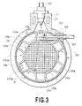
- the support member 150 in the present embodiment is formed in a corrugated shape in cross section by pressing a sheet of rectangular flat plate, which has outer arc-shaped portions 150a along and in contact with the inner periphery of the exhaust pipe 30, inner arc-shaped portions 150b along and in contact with the outer periphery of the cylindrical casing 130a which is the outer peripheral member of the burner catalyst 130, and coupling portions 150c each coupling the outer arc-shaped portion 150a and the inner arc-shaped portion 150b to each other.
- the outer arc-shaped portion 150a and each of the coupling portions 150c on both sides of the outer arc-shaped portion 150a form an angle ⁇ in a plane orthogonal to the axis of the exhaust pipe 30, and likewise the inner arc-shaped portion 150b and each of the coupling portions 150c on both sides of the inner arc-shaped portion 150b form an angle ⁇ in a plane orthogonal to the axis of the exhaust pipe 30.
- the angle ⁇ is set as an obtuse angle (for example, 120 degrees) to prevent the coupling portion 150c from buckling at thermal expansion.
- the support member 150 in the present embodiment is formed by being split into two parts made of an upper half and a lower half of the support member 150, each having three crests (protrusions) ( Fig. 6 shows only the upper half of the support member 150).
- the support member 150 may be formed in a ring shape in one piece without being split.
- the burner catalyst 130 is mounted in the exhaust pipe 30 as follows. Specifically, one of the upper and lower halves of the support member 150, in which a through hole (shown as 150d in Fig. 6 for the sake of convenience because it is not visually recognized on the final product) is formed at the center in approximately the width direction of the inner arc-shaped portion 150b having a width in a predetermined axial direction, is positioned at the center in the axial direction of the cylindrical casing 130a of the burner catalyst 130. Then, the plug welding is performed on the through hole 150d, and then the one of the upper and lower halves of the support member 150 is fixedly secured to the cylindrical casing 130a.
- a through hole shown as 150d in Fig. 6 for the sake of convenience because it is not visually recognized on the final product
- the other of the upper and lower halves of the support member 150 is positioned on the cylindrical casing 130a, and similarly the plug welding is performed.
- the support member 150 is fixedly secured to approximately the center in the axial direction of the cylindrical casing 130a of the burner catalyst 130.
- the through hole 150d may be formed in not all of the inner arc-shaped portions 150b but at least one thereof (refer to Fig. 6 ).
- the burner catalyst 130 with the support member 150 fixedly secured thereto is inserted into the exhaust pipe 30 from the opening on which the right flange 30A in Fig. 2 is placed, and then held in a predetermined place by friction contact between the outer arc-shaped portions 150a of the support member 150 and the inner periphery of the exhaust pipe 30.
- the burning flame passes through the in-catalyst passage 130b in the burner catalyst 130 held through the support member 150, and also passes through the catalyst bypass passage 130c between the burner catalyst 130 and the exhaust pipe 30.
- the exhaust pipe 30, the burner catalyst 130 and the like are heated and thermally expand.
- each of the angles ⁇ formed in a plane orthogonal to the axis of the exhaust pipe 30 by the outer arc-shaped portion 150a of the support member 150 and the coupling portion 150c and by the inner arc-shaped portion 150b and the coupling portion 150c is an obtuse angle, even if a difference in thermal expansion in the radial direction occurs between the exhaust pipe 30 and the cylindrical casing 130a of the burner catalyst 130, the coupling 150c can elastically deform without buckling to lessen the thermal stress.
- the casing 130a of the burner catalyst 130 thermally expands in the axial direction, since the casing 130a is supported at its center in the axial direction by the supporting member 150, the casing 130a is freely capable of thermally expanding in the axial direction. Accordingly, large thermal stress is prevented from occurring on the cylindrical casing 130a.
- the support member 150 is fixedly secured to the cylindrical casing 130a of the burner catalyst 130 by the plug welding using the through hole 150d provided in at least one inner arc-shaped portion 150b, the area for coupling the support member 150 and the cylindrical casing 130a is limited only to the size of the through hole 150d.
- the method is practicable with a small number of welding places and in a short time. Because of this, even if the welding process is included, the manufacturing can be performed relatively easily and the mass production is possible.
- the axis of the exhaust pipe 30 is parallel to a passage 130ca formed between the exhaust pipe 30 and the support member 150 (specifically, the area enclosed by the exhaust pipe 30, the inner arc-shaped portion 150b and the opposite coupling portions 150c), and a passage 130cb formed between the support member 150 and the casing 130a which is the outer periphery member of the burner catalyst 130 (specifically, the area enclosed by the casing 130a, the outer arc-shaped portion 150a and the opposite coupling portion 150c), which form a part in the axial direction of the ring-shaped catalyst bypass passage 130c between the outer periphery of the aforementioned casing 130a and the exhaust pipe 30.
- the support member 150 may be formed in a twist manner such that each of the passage 130ca and the passage 130cb is not in parallel to the axis of the exhaust pipe 30, but extends in a spiral fashion.
- the inner arc-shaped portion 150b of the recess of the support member 150 corrugated in cross section is formed to be in parallel to the axis of the exhaust pipe, while the outer arc-shaped portion 150a of the projection is not formed in parallel to the axis of the exhaust pipe, but is formed in a twist manner.
- both of the outer arc-shaped portion 150a of the protrusion and the inner arc-shaped portion 150b of the recess may not be formed in parallel to the axis of the exhaust pipe, but may be formed in a twist manner.
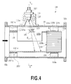
- the second embodiment differs from the first embodiment in that an introduction cylinder for accelerating introduction of fuel into the burner catalyst 130 and an additional support member are additionally provided, so that components identical to those in the first embodiment are shown in the drawings by the identical reference signs, and a repeated description is avoided.
- the burner device 100 further includes an introduction cylinder 160 that is approximately identical in diameter with the burner catalyst 130 and is placed upstream of the burner catalyst 130.
- the introduction cylinder 160 is integrally attached by engaging a rear end of the introducing cylinder 160 with a front end of the casing 130a of the burner catalyst 130, and extends from the casing 130a toward the upstream direction.
- an approximately semicircular cross-section opening 160a is formed in an upper half portion of a central side face in the axial direction of the introduction cylinder 160, and a lower half portion of the introduction cylinder 160 is formed as an approximately semicircular cross-section tub-shaped portion 160b.
- the introduction cylinder 160 In the opening 160a, the fuel supply valve 110, the glow plug 120 and the collision plate 140 for collision of the supplied fuel are placed.
- the introduction cylinder 160 has a front end supported in the exhaust pipe 30 by an additional support member 150'.
- the introduction cylinder 160 receives the supplied fuel F supplied through the opening 160a on the tub-shaped portion 160b of the lower half portion, and then introduces and guides the supplied fuel F into the burner catalyst 130 while using the flow of the exhaust gas.
- the additional support member 150' is formed to be corrugated in cross section, which has outer arc-shaped portions 150'a in contact with the inner periphery of the exhaust pipe 30, inner arc-shaped portions 150'b in contact with the outer periphery of the introduction cylinder 160, and coupling portions 150'c each coupling the outer arc-shaped portion 150'a and the inner arc-shaped portion 150'b.
- the outer arc-shaped portion 150'a and the inner arc-shaped portion 150'b of the additional support member 150' is plug-welded respectively to the exhaust pipe 30 and the introduction cylinder 160.
- the inner arc-shaped portion 150b of the support member 150 is plug-welded to the casing 130a of the burner catalyst 130, but the outer arc-shaped portion 150a of the support member 150 is not welded to the exhaust pipe 30 so as to be slidable in the axial direction.
- the burner catalyst 130 and the introduction cylinder 160 located upstream thereof are mounted in the exhaust pipe 30 as follows.
- the support member 150 is fixedly secured, by plug welding, to approximately the center in the axial direction of the cylindrical casing 130a of the burner catalyst 130 including the introduction cylinder 160 integrally attached.
- the inner arc-shaped portion 150' b of the additional support member 150' is fixedly secured to the outer periphery of the front end of the introduction cylinder 160 by plug welding.
- the support member 150 and the additional support member 150' are fixedly secured, and then the burner catalyst 130 combined with the introduction cylinder 160 is inserted into the exhaust pipe 30 from the opening on which, for example, the right flange 30A is provided in Fig. 4 .
- the outer arc-shaped portion 150' a of the additional support member 150' is fixedly secured to the exhaust pipe 30 by plug welding (it should be noted that, in this case, a through hole not shown, is provided in at least one of the outer arc-shaped portions 150'a of the additional support member 150').
- the outer arc-shaped portion 150a of the support member 150 and the exhaust pipe 30 are not welded to each other, and maintain friction contact with each other so as to be slidable in the axial direction.
- the fuel supply valve 110 injects the fuel F obliquely downward and slightly toward the downstream direction to direct it from above through the opening 160a of the introduction cylinder 160 toward the bottom surface of the tub-shaped portion 160b of the introduction cylinder 160.
- the ejected fuel F moves along a fuel path having a predetermined spraying angle.
- the heating portion 120a of the glow plug 120 and the collision plate 140 are placed along the fuel path.
- the collision plate 140 is placed in a position close to and slightly below the heating portion 120a.
- the glow plug 120 and the collision plate 140 are inserted into the exhaust pipe 30 from an upper side of the exhaust pipe 30 and linearly extend in parallel to each other and in the horizontal direction.
- the glow plug 120 When the fuel supplied from the fuel supply valve 110 is ignited by the glow plug 120, the burning flame is guided by the introduction cylinder 160 (in particular, the tub-shaped portion 160b), while passing through the in-catalyst passages 130b in the burner catalyst 130 held via the support member 150, and also passing through the catalyst bypass passage 130c located between the burner catalyst 130 and the exhaust pipe 30.
- the introduction cylinder 160 in particular, the tub-shaped portion 160b
- micronization and atomization of the fuel F is accelerated, improving the dispersibility and the diffusivity. Accordingly, the ignition caused by the glow plug 120 is accelerated.
- the glow plug 120 is situated at a level approximately equal to that of the catalyst bypass passage 130c above the burner catalyst 130, so that the flame produced by the ignition spreads mainly toward the inside of the catalyst bypass passage 130c located above the glow plug 120.
- the fuel supplied without stopping at the collision plate 140 is guided to the tub-shaped portion 160b of the introduction cylinder 160 as described earlier, then is oxidized and reformed in the burner catalyst 130, and then is discharged from the burner catalyst 130. Then, the reformed fuel is fully oxidized and burned in the oxidation catalytic converter 6 in the downstream side, to be used for further rise in temperature of the exhaust gas or the like.
- the exhaust pipe 30, the burner catalyst 130, the introduction cylinder 160 and the like are heated to be thermally expanded. Therefore, even if a difference in thermal expansion occurs between the exhaust pipe 30 and, the introduction cylinder 160 and the cylindrical casing 130a of the burner catalyst 130 combined with the introduction cylinder 160, the differences in thermal expansion in the radial direction and the axial direction of the burner device 100 are absorbed by the support member 150 formed in a corrugated cross section and the additional support member 150'. That is, in the radial direction of the burner device 100, as in the case of the first embodiment, the support member 150 and the additional support member 150' which are formed in a corrugated shape having an obtuse angle ⁇ elastically support and absorb.
- the modification example has commonalities with the aforementioned support member 150 in a basic main body, but differs in that strip-shaped portions 150e are added integrally with the inner arc-shaped portion 150b (hereinafter the support member including the strip-shaped portions 150e is designated by "150E").
- the strip-shaped portion 150e is provided for preventing welding heat from excessively affecting the burner catalyst 130 when the support member 150 is welded to be fixedly secured to the cylindrical casing 130a of the burner device 130.
- I-groove welding is applied between the end of the strip-shaped portion 150e and the end of the cylindrical casing 130a of the burner catalyst 30, thus preventing the welding heat from excessively affecting the inside of the burner catalyst 130.
- the support member 150E is particularly effective for the burner catalyst 130 of the metallic substrate type to which brazing is applied as described earlier because the brazed area is prevented from being damaged.
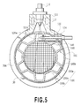
- a third embodiment according to the present invention will be described with reference to Fig. 9 .
- the third embodiment differs from the second embodiment only in that a separate ring-shaped member and a cushioning mat are added to the inner periphery of the exhaust pipe. Therefore, the differences are mainly described and components identical to those in the second embodiment are shown in the drawings by the identical reference signs, and a repeated description is avoided.
- a separate ring-shaped member 170 is provided on the inner periphery of the exhaust pipe 30.
- a cushioning mat 180 is interposed between the ring-shaped member 170 and the exhaust pipe 30.
- the cylindrical casing 130a of the burner catalyst 130 is held via the support member 150E in the ring-shaped member 170. That is, the outer arc-shaped portions 150a of the support member 150E in which the strip-shaped portions 150e combined with the inner arc-shaped portions 150b are I-groove-welded to the cylindrical casing 130a are in friction contact with the ring-shaped member 170.
- the outer arc-shaped portion 150a of the support member 150E is not fixedly secured to the ring-shaped member 170 so as to be able to slide in the axial direction.
- the cushioning mat 180 may be a mat made of alumina fiber having high heat resistance.
- the outer arc-shaped portion 150a of the support member 150E is not secured to the ring-shaped member 170 and is slidable in the axial direction, this absorbs a difference in thermal expansion in the axial direction.
- a difference in thermal expansion in the radial direction is absorbed with reliability by deformation of the cushioning mat 180 in addition to the support member 150E, and also impact loads can be absorbed.
Landscapes
- Engineering & Computer Science (AREA)
- Chemical & Material Sciences (AREA)
- Chemical Kinetics & Catalysis (AREA)
- Combustion & Propulsion (AREA)
- Mechanical Engineering (AREA)
- General Engineering & Computer Science (AREA)
- Health & Medical Sciences (AREA)
- Toxicology (AREA)
- Materials Engineering (AREA)
- Exhaust Gas After Treatment (AREA)
- Incineration Of Waste (AREA)
Applications Claiming Priority (1)
| Application Number | Priority Date | Filing Date | Title |
|---|---|---|---|
| PCT/JP2011/000522 WO2012104894A1 (fr) | 2011-01-31 | 2011-01-31 | Dispositif de brûleur pour augmentation de la température des gaz d'échappement |
Publications (2)
| Publication Number | Publication Date |
|---|---|
| EP2672085A1 true EP2672085A1 (fr) | 2013-12-11 |
| EP2672085A4 EP2672085A4 (fr) | 2017-08-09 |
Family
ID=46602150
Family Applications (1)
| Application Number | Title | Priority Date | Filing Date |
|---|---|---|---|
| EP11857868.1A Withdrawn EP2672085A4 (fr) | 2011-01-31 | 2011-01-31 | Dispositif de brûleur pour augmentation de la température des gaz d'échappement |
Country Status (5)
| Country | Link |
|---|---|
| US (1) | US9016051B2 (fr) |
| EP (1) | EP2672085A4 (fr) |
| JP (1) | JP5605441B2 (fr) |
| CN (1) | CN103348108B (fr) |
| WO (1) | WO2012104894A1 (fr) |
Families Citing this family (18)
| Publication number | Priority date | Publication date | Assignee | Title |
|---|---|---|---|---|
| WO2012004831A1 (fr) * | 2010-07-07 | 2012-01-12 | トヨタ自動車株式会社 | Moteur à combustion interne |
| JP6123190B2 (ja) * | 2012-08-30 | 2017-05-10 | 株式会社Ihi | 排気システム |
| JP6123191B2 (ja) * | 2012-08-30 | 2017-05-10 | 株式会社Ihi | 排気システム |
| JP5812038B2 (ja) * | 2013-04-19 | 2015-11-11 | コベルコ建機株式会社 | 建設機械の排気構造 |
| CN103742927B (zh) * | 2014-01-20 | 2015-10-28 | 扬州澄露环境工程有限公司 | 垃圾焚烧炉烟气升温装置 |
| JP2015169397A (ja) * | 2014-03-08 | 2015-09-28 | 株式会社上野商店 | 燃焼促進用煙突筒 |
| AT515898B1 (de) * | 2014-05-20 | 2017-09-15 | Ge Jenbacher Gmbh & Co Og | Verfahren zur Abgasnachbehandlung |
| AT515887A1 (de) | 2014-05-20 | 2015-12-15 | Ge Jenbacher Gmbh & Co Og | Verfahren zum Anfahren eines Thermoreaktors |
| US9689293B2 (en) * | 2014-08-19 | 2017-06-27 | Continental Automotive Systems, Inc. | Reductant delivery unit for automotive selective catalytic reduction with optimized fluid heating |
| US20150377108A1 (en) * | 2015-09-04 | 2015-12-31 | Caterpillar Inc. | Dual fuel engine system |
| AT517669A1 (de) * | 2015-09-04 | 2017-03-15 | Ge Jenbacher Gmbh & Co Og | Brennkraftmaschine |
| AT517670B1 (de) | 2015-09-04 | 2023-03-15 | Innio Jenbacher Gmbh & Co Og | Abgasnachbehandlungsvorrichtung |
| WO2018192663A1 (fr) * | 2017-04-20 | 2018-10-25 | Volvo Penta Corporation | Dispositif mélangeur, son utilisation et procédé de mélange |
| KR101867540B1 (ko) * | 2018-04-03 | 2018-06-15 | 화이버텍(주) | 차량용 배기가스 저감장치 |
| JP7217654B2 (ja) * | 2019-03-26 | 2023-02-03 | 日本碍子株式会社 | 熱交換器 |
| CN110630366B (zh) * | 2019-10-22 | 2021-11-19 | 蒙城县弘文信息科技有限公司 | 一种环保用便于拆卸清洗的汽车尾气排放过滤装置 |
| US12276218B2 (en) * | 2023-02-10 | 2025-04-15 | Beecher Emission Solution Technologies, LLC | System for lighting off an auxiliary occupational emissions device and method of operating the same |
| DE102023122361A1 (de) * | 2023-08-22 | 2025-02-27 | Purem GmbH | Anschlusseinheit |
Family Cites Families (13)
| Publication number | Priority date | Publication date | Assignee | Title |
|---|---|---|---|---|
| DE3720829A1 (de) * | 1987-06-24 | 1989-01-05 | Zeuna Staerker Kg | Verfahren und vorrichtung zum reinigen eines russfilters |
| US5238650A (en) * | 1991-09-13 | 1993-08-24 | W. R. Grace & Co.-Conn. | Electrode feed through |
| JPH0828255A (ja) * | 1994-07-19 | 1996-01-30 | Nippondenso Co Ltd | 排ガス浄化用コンバータ |
| JPH0893459A (ja) * | 1994-09-20 | 1996-04-09 | Nissan Motor Co Ltd | エンジンの排気浄化装置 |
| JP3845873B2 (ja) * | 1994-10-03 | 2006-11-15 | 株式会社デンソー | セラミック触媒コンバータ |
| DE19504183A1 (de) * | 1995-02-09 | 1996-08-14 | Eberspaecher J | Brenner zur thermischen Regeneration eines Partikelfilters in einem Abgasnachbehandlungssystem eines Verbrennungsmotors, insbesondere Dieselmotors |
| JP2001012235A (ja) | 1999-06-29 | 2001-01-16 | Honda Motor Co Ltd | エンジンの排気浄化器 |
| DE10137878A1 (de) * | 2001-08-02 | 2003-02-27 | Emitec Emissionstechnologie | Abgaskatalysator mit Dehnungen ausgleichender Lagerung |
| EP1495215B1 (fr) * | 2002-04-18 | 2006-03-29 | Emitec Gesellschaft für Emissionstechnologie mbH | Corps support catalyseur calibre et dote d'une enveloppe ondulee et son procede de production |
| DE102006019052A1 (de) * | 2006-04-25 | 2007-10-31 | Robert Bosch Gmbh | Einbauteil zur Montage in einem Abgasstrang |
| US8375705B2 (en) * | 2008-05-30 | 2013-02-19 | Caterpillar Inc. | Exhaust system implementing low-temperature regeneration strategy |
| JP4569690B2 (ja) * | 2008-09-04 | 2010-10-27 | トヨタ自動車株式会社 | 内燃機関の排気浄化装置 |
| US8943803B2 (en) * | 2010-10-27 | 2015-02-03 | Caterpillar Inc. | Power system with cylinder-disabling strategy |
-
2011
- 2011-01-31 WO PCT/JP2011/000522 patent/WO2012104894A1/fr not_active Ceased
- 2011-01-31 CN CN201180066493.3A patent/CN103348108B/zh not_active Expired - Fee Related
- 2011-01-31 EP EP11857868.1A patent/EP2672085A4/fr not_active Withdrawn
- 2011-01-31 US US13/989,994 patent/US9016051B2/en not_active Expired - Fee Related
- 2011-01-31 JP JP2012555552A patent/JP5605441B2/ja not_active Expired - Fee Related
Non-Patent Citations (1)
| Title |
|---|
| See references of WO2012104894A1 * |
Also Published As
| Publication number | Publication date |
|---|---|
| EP2672085A4 (fr) | 2017-08-09 |
| CN103348108A (zh) | 2013-10-09 |
| US9016051B2 (en) | 2015-04-28 |
| JP5605441B2 (ja) | 2014-10-15 |
| JPWO2012104894A1 (ja) | 2014-07-03 |
| US20130276437A1 (en) | 2013-10-24 |
| CN103348108B (zh) | 2015-10-07 |
| WO2012104894A1 (fr) | 2012-08-09 |
Similar Documents
| Publication | Publication Date | Title |
|---|---|---|
| US9016051B2 (en) | Burner device for raising temperature of exhaust gas | |
| EP1357269B1 (fr) | Dispositif de purification de gaz d'échappement | |
| EP1704308B1 (fr) | Systeme d'echappement avec un filtre a particules pour moteur a combustion interne a melange pauvre | |
| US12607140B2 (en) | Exhaust system and features thereof | |
| JP2010084710A (ja) | 内燃機関の排気浄化装置 | |
| JP5120503B2 (ja) | 内燃機関 | |
| JP5206884B2 (ja) | 内燃機関 | |
| WO2012066606A1 (fr) | Dispositif de purification de gaz d'échappement pour moteur à combustion interne | |
| WO2011101896A1 (fr) | Dispositif de purification des gaz d'échappement pour moteur à combustion interne | |
| JP2011247208A (ja) | 内燃機関 | |
| JP2008232061A (ja) | ディーゼルエンジンの排気装置 | |
| JP5206885B2 (ja) | 内燃機関 | |
| EP4048431A1 (fr) | Système d'échappement et ses caractéristiques | |
| WO2012137247A1 (fr) | Moteur à combustion interne équipé d'un appareil brûleur | |
| JP2012107634A (ja) | 内燃機関の排気浄化装置 | |
| JP2011220302A (ja) | 内燃機関の排気装置 | |
| JP2011236852A (ja) | 内燃機関 | |
| AU2020369432A1 (en) | Exhaust system and features thereof | |
| WO2012001733A1 (fr) | Moteur à combustion interne | |
| JP2011252438A (ja) | 内燃機関 | |
| JP2011236851A (ja) | 内燃機関 | |
| JP2012241624A (ja) | バーナー装置を備える内燃機関 | |
| JP2012087681A (ja) | 排気浄化装置 |
Legal Events
| Date | Code | Title | Description |
|---|---|---|---|
| PUAI | Public reference made under article 153(3) epc to a published international application that has entered the european phase |
Free format text: ORIGINAL CODE: 0009012 |
|
| 17P | Request for examination filed |
Effective date: 20130819 |
|
| AK | Designated contracting states |
Kind code of ref document: A1 Designated state(s): AL AT BE BG CH CY CZ DE DK EE ES FI FR GB GR HR HU IE IS IT LI LT LU LV MC MK MT NL NO PL PT RO RS SE SI SK SM TR |
|
| DAX | Request for extension of the european patent (deleted) | ||
| RA4 | Supplementary search report drawn up and despatched (corrected) |
Effective date: 20170710 |
|
| RIC1 | Information provided on ipc code assigned before grant |
Ipc: F01N 3/02 20060101ALI20170704BHEP Ipc: F01N 3/38 20060101ALI20170704BHEP Ipc: F01N 3/28 20060101ALI20170704BHEP Ipc: F01N 3/08 20060101ALI20170704BHEP Ipc: F01N 3/36 20060101AFI20170704BHEP Ipc: F01N 3/20 20060101ALI20170704BHEP Ipc: F01N 3/025 20060101ALI20170704BHEP Ipc: F01N 3/10 20060101ALI20170704BHEP |
|
| STAA | Information on the status of an ep patent application or granted ep patent |
Free format text: STATUS: REQUEST FOR EXAMINATION WAS MADE |
|
| STAA | Information on the status of an ep patent application or granted ep patent |
Free format text: STATUS: THE APPLICATION IS DEEMED TO BE WITHDRAWN |
|
| 18D | Application deemed to be withdrawn |
Effective date: 20180207 |