WO2011101896A1 - Dispositif de purification des gaz d'échappement pour moteur à combustion interne - Google Patents
Dispositif de purification des gaz d'échappement pour moteur à combustion interne Download PDFInfo
- Publication number
- WO2011101896A1 WO2011101896A1 PCT/JP2010/000993 JP2010000993W WO2011101896A1 WO 2011101896 A1 WO2011101896 A1 WO 2011101896A1 JP 2010000993 W JP2010000993 W JP 2010000993W WO 2011101896 A1 WO2011101896 A1 WO 2011101896A1
- Authority
- WO
- WIPO (PCT)
- Prior art keywords
- catalyst
- exhaust
- internal combustion
- combustion engine
- oxidation catalyst
- Prior art date
- Legal status (The legal status is an assumption and is not a legal conclusion. Google has not performed a legal analysis and makes no representation as to the accuracy of the status listed.)
- Ceased
Links
Images


Classifications
-
- F—MECHANICAL ENGINEERING; LIGHTING; HEATING; WEAPONS; BLASTING
- F01—MACHINES OR ENGINES IN GENERAL; ENGINE PLANTS IN GENERAL; STEAM ENGINES
- F01N—GAS-FLOW SILENCERS OR EXHAUST APPARATUS FOR MACHINES OR ENGINES IN GENERAL; GAS-FLOW SILENCERS OR EXHAUST APPARATUS FOR INTERNAL-COMBUSTION ENGINES
- F01N3/00—Exhaust or silencing apparatus having means for purifying, rendering innocuous, or otherwise treating exhaust
- F01N3/08—Exhaust or silencing apparatus having means for purifying, rendering innocuous, or otherwise treating exhaust for rendering innocuous
- F01N3/10—Exhaust or silencing apparatus having means for purifying, rendering innocuous, or otherwise treating exhaust for rendering innocuous by thermal or catalytic conversion of noxious components of exhaust
- F01N3/18—Exhaust or silencing apparatus having means for purifying, rendering innocuous, or otherwise treating exhaust for rendering innocuous by thermal or catalytic conversion of noxious components of exhaust characterised by methods of operation; Control
- F01N3/20—Exhaust or silencing apparatus having means for purifying, rendering innocuous, or otherwise treating exhaust for rendering innocuous by thermal or catalytic conversion of noxious components of exhaust characterised by methods of operation; Control specially adapted for catalytic conversion
- F01N3/2006—Periodically heating or cooling catalytic reactors, e.g. at cold starting or overheating
- F01N3/2033—Periodically heating or cooling catalytic reactors, e.g. at cold starting or overheating using a fuel burner or introducing fuel into exhaust duct
-
- F—MECHANICAL ENGINEERING; LIGHTING; HEATING; WEAPONS; BLASTING
- F01—MACHINES OR ENGINES IN GENERAL; ENGINE PLANTS IN GENERAL; STEAM ENGINES
- F01N—GAS-FLOW SILENCERS OR EXHAUST APPARATUS FOR MACHINES OR ENGINES IN GENERAL; GAS-FLOW SILENCERS OR EXHAUST APPARATUS FOR INTERNAL-COMBUSTION ENGINES
- F01N3/00—Exhaust or silencing apparatus having means for purifying, rendering innocuous, or otherwise treating exhaust
- F01N3/08—Exhaust or silencing apparatus having means for purifying, rendering innocuous, or otherwise treating exhaust for rendering innocuous
- F01N3/10—Exhaust or silencing apparatus having means for purifying, rendering innocuous, or otherwise treating exhaust for rendering innocuous by thermal or catalytic conversion of noxious components of exhaust
- F01N3/103—Oxidation catalysts for HC and CO only
-
- F—MECHANICAL ENGINEERING; LIGHTING; HEATING; WEAPONS; BLASTING
- F01—MACHINES OR ENGINES IN GENERAL; ENGINE PLANTS IN GENERAL; STEAM ENGINES
- F01N—GAS-FLOW SILENCERS OR EXHAUST APPARATUS FOR MACHINES OR ENGINES IN GENERAL; GAS-FLOW SILENCERS OR EXHAUST APPARATUS FOR INTERNAL-COMBUSTION ENGINES
- F01N2610/00—Adding substances to exhaust gases
- F01N2610/03—Adding substances to exhaust gases the substance being hydrocarbons, e.g. engine fuel
-
- F—MECHANICAL ENGINEERING; LIGHTING; HEATING; WEAPONS; BLASTING
- F01—MACHINES OR ENGINES IN GENERAL; ENGINE PLANTS IN GENERAL; STEAM ENGINES
- F01N—GAS-FLOW SILENCERS OR EXHAUST APPARATUS FOR MACHINES OR ENGINES IN GENERAL; GAS-FLOW SILENCERS OR EXHAUST APPARATUS FOR INTERNAL-COMBUSTION ENGINES
- F01N3/00—Exhaust or silencing apparatus having means for purifying, rendering innocuous, or otherwise treating exhaust
- F01N3/02—Exhaust or silencing apparatus having means for purifying, rendering innocuous, or otherwise treating exhaust for cooling, or for removing solid constituents of, exhaust
- F01N3/021—Exhaust or silencing apparatus having means for purifying, rendering innocuous, or otherwise treating exhaust for cooling, or for removing solid constituents of, exhaust by means of filters
- F01N3/023—Exhaust or silencing apparatus having means for purifying, rendering innocuous, or otherwise treating exhaust for cooling, or for removing solid constituents of, exhaust by means of filters using means for regenerating the filters, e.g. by burning trapped particles
- F01N3/025—Exhaust or silencing apparatus having means for purifying, rendering innocuous, or otherwise treating exhaust for cooling, or for removing solid constituents of, exhaust by means of filters using means for regenerating the filters, e.g. by burning trapped particles using fuel burner or by adding fuel to exhaust
- F01N3/0253—Exhaust or silencing apparatus having means for purifying, rendering innocuous, or otherwise treating exhaust for cooling, or for removing solid constituents of, exhaust by means of filters using means for regenerating the filters, e.g. by burning trapped particles using fuel burner or by adding fuel to exhaust adding fuel to exhaust gases
-
- Y—GENERAL TAGGING OF NEW TECHNOLOGICAL DEVELOPMENTS; GENERAL TAGGING OF CROSS-SECTIONAL TECHNOLOGIES SPANNING OVER SEVERAL SECTIONS OF THE IPC; TECHNICAL SUBJECTS COVERED BY FORMER USPC CROSS-REFERENCE ART COLLECTIONS [XRACs] AND DIGESTS
- Y02—TECHNOLOGIES OR APPLICATIONS FOR MITIGATION OR ADAPTATION AGAINST CLIMATE CHANGE
- Y02T—CLIMATE CHANGE MITIGATION TECHNOLOGIES RELATED TO TRANSPORTATION
- Y02T10/00—Road transport of goods or passengers
- Y02T10/10—Internal combustion engine [ICE] based vehicles
- Y02T10/12—Improving ICE efficiencies
Definitions
- the present invention relates to an exhaust purification device for an internal combustion engine.
- An object of the present invention is to suppress the temperature difference between exhausts reaching the downstream exhaust purification catalyst while suppressing the overall length of the exhaust system.
- a first catalyst disposed in an exhaust passage from an internal combustion engine, and an exhaust passage upstream of the first catalyst are disposed in the first catalyst.
- a second catalyst through which a part of the exhaust gas flows, and a part of the exhaust gas that has passed through the inside of the second catalyst from the downstream end of the second catalyst are separated from the outer peripheral surface of the second catalyst.
- An exhaust purification device for an internal combustion engine comprising: a guide member that is guided upstream to the upstream side and that discharges into the exhaust passage.
- the guide member causes at least a part of the exhaust gas that has passed through the inside of the second catalyst to be upstream from the end on the downstream side of the second catalyst along the outer peripheral surface of the second catalyst. And is discharged into the exhaust passage. Therefore, it is possible to suppress the temperature difference of the exhaust gas that reaches the exhaust purification catalyst on the downstream side while suppressing the overall length of the exhaust system.
- the guide member includes a first part extending along the outer peripheral surface of the second catalyst from the vicinity of the downstream end of the second catalyst.
- the first part has at least one adjustment hole through which exhaust gas can circulate in an intermediate part thereof.
- the first part has an opening at its upstream end
- the guide member further includes a second part that covers the upstream side of the opening.
- an inner end of the second part is fixed to the second catalyst, an outer end of the second part is closer to the wall surface of the exhaust passage than the first part, and the second part
- An outer peripheral side passage is formed between the outer end of the component and the wall surface of the exhaust passage.
- Another aspect of the present invention further includes a fuel supply valve for supplying fuel to the second catalyst.
- the temperature of the second catalyst can be suitably raised.
- the present invention it is possible to suppress the temperature difference of the exhaust gas that reaches the downstream exhaust purification catalyst while suppressing the overall length of the exhaust system.
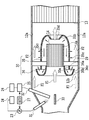
- FIG. 1 is a schematic view of a first embodiment of the present invention.
- FIG. 2 is a cross-sectional view showing the main part of the first embodiment.
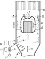
- FIG. 3 is a cross-sectional view showing the main part of the second embodiment.
- FIG. 4 is a cross-sectional view showing the main part of the third embodiment.
- an internal combustion engine 1 to which an embodiment of the present invention is applied is a compression ignition type engine having four combustion chambers 2.
- the internal combustion engine 1 has an electronically controlled fuel injection valve 3 for injecting fuel into the combustion chamber 2.
- An intake manifold 4 and an exhaust manifold 5 communicate with the combustion chamber 2.
- the intake manifold 4 is connected to the outlet of the compressor 7 a of the exhaust turbocharger 7 through the intake duct 6, and the inlet of the compressor 7 a is connected to the air cleaner 9 through the air flow meter 8.
- a throttle valve 10 driven by a step motor is arranged in the intake duct 6, and a cooling device 11 for cooling intake air flowing in the intake duct 6 is arranged around the intake duct 6.
- the exhaust manifold 5 and the intake manifold 4 are connected to each other via an exhaust gas recirculation (hereinafter referred to as EGR) passage 18.
- An EGR control valve 19 is disposed in the EGR passage 18.
- a cooling device 20 is arranged.
- Each fuel injection valve 3 is connected to a common rail 22 via a fuel supply pipe 21, and this common rail 22 is connected to a fuel tank 24 via an electronically controlled variable discharge pump 23.
- the fuel stored in the fuel tank 24 is supplied into the common rail 22 by the fuel pump 23, and the fuel supplied into the common rail 22 is supplied to the fuel injection valve 3 through each fuel supply pipe 21.
- the exhaust manifold 5 is connected to an inlet of an exhaust turbine 7b of the exhaust turbocharger 7, and an outlet of the exhaust turbine 7b is connected to an exhaust purification catalyst 13 having an oxidation function via an exhaust pipe 12.
- an exhaust purification catalyst 13 having an oxidation function via an exhaust pipe 12.
- a guide member 30 containing the small oxidation catalyst 14 is disposed in the engine exhaust passage upstream of the exhaust purification catalyst 13, that is, in the exhaust pipe 12.
- the exhaust purification catalyst 13 is composed of an oxidation catalyst, and a particulate filter 16 for collecting particulates in the exhaust is disposed in the exhaust pipe 12 downstream of the exhaust purification catalyst 13.
- a NOx storage catalyst 17 is arranged in the exhaust pipe 12 downstream of the particulate filter 16.
- the oxidation catalyst 13 is formed of a monolith catalyst carrying a noble metal catalyst such as platinum Pt.
- the noble metal catalyst is not supported on the particulate filter 16.
- a noble metal catalyst such as platinum Pt can be supported on the particulate filter 16, and in this case, the oxidation catalyst 13 can be omitted.
- the NOx occlusion catalyst 17 also carries a catalyst carrier made of alumina, for example, on the substrate.
- a noble metal catalyst such as platinum Pt is dispersed and supported on the surface of the catalyst carrier, and a layer of NOx absorbent is formed on the surface of the catalyst carrier.
- the NOx absorbent 47 absorbs and releases NOx when the air-fuel ratio of the exhaust gas is lean, and performs an NOx absorbing and releasing action that releases the stored NOx when the oxygen concentration in the exhaust gas decreases.
- the small oxidation catalyst 14 has a smaller volume than the exhaust purification catalyst 13 and a part of the exhaust gas flowing into the exhaust purification catalyst 13 circulates.
- the small oxidation catalyst 14 has a base having a laminated structure of a thin metal flat plate and a thin metal corrugated plate, and a catalyst carrier layer made of alumina, for example, is formed on the surface of the base.
- the substrate can also be formed from cordierite.
- a noble metal catalyst such as platinum Pt, rhodium Rd, and palladium Pd is supported on the catalyst carrier.
- the small oxidation catalyst 14 has a cross section smaller than the cross section of the entire exhaust gas flow toward the exhaust purification catalyst 13, that is, a cross section smaller than the cross section of the exhaust pipe 12, and the exhaust flow at the center in the exhaust pipe 12. It has a cylindrical shape extending in the direction.
- the substrate is a so-called straight flow type in which individual cells communicate from upstream to downstream.
- the small oxidation catalyst 14 is arranged in a cylindrical outer frame 14a, and the cylindrical outer frame 14a is supported in the exhaust pipe 12 by a plurality of radially arranged stays 29.
- a fuel supply valve 31, a glow plug 32, and a collision member 33 are disposed in the exhaust pipe 12 upstream of the small oxidation catalyst 14.
- the fuel supply valve 31 is connected to the fuel tank 24 via the fuel pump 23 or a second fuel pump (not shown), and supplies fuel into the exhaust pipe 12 upstream of the small oxidation catalyst 14.
- the glow plug 32 is connected to the in-vehicle DC power supply 26 via the booster circuit 25 and ignites the supplied fuel.
- the collision member 33 is disposed substantially at the center of the cross section of the exhaust pipe 12 and collides with the injected fuel in order to efficiently guide the fuel injected from the fuel supply valve 31 to the glow plug 32 and the small oxidation catalyst 14. And reflect.
- the fuel supply valve 31 and the glow plug 32 are controlled by an electronic control unit (ECU) 27 based on detection and estimation of the temperature and load status of each part.
- the ECU 27 comprises a well-known digital computer, and includes a ROM (read only memory), a RAM (random access memory), a CPU (microprocessor), an input port and an output port which are connected to each other by a bidirectional bus.
- the ECU 27 can detect the state of the vehicle as a control condition by using a temperature sensor and / or a differential pressure sensor arranged in the vicinity of each catalyst in the exhaust pipe 12, and for example, from a detected value such as an engine water temperature. Can be estimated.
- the exhaust purification catalyst 13 when the exhaust purification catalyst 13 is not activated, such as when the engine is started, when it is activated, the reformed fuel is transferred from the small oxidation catalyst 14 in order to burn particulate matter deposited on the particulate filter 16.
- the fuel supply valve 31 and the glow plug 32 are operated to burn the fuel, or only the fuel supply valve 31 is operated to make the fuel a small oxidation catalyst. 14 can be supplied.
- a guide member 30 is disposed around the small oxidation catalyst 14. As shown in FIG. 2, the guide member 30 allows a part of the exhaust gas that has passed through the inside of the small oxidation catalyst 14 to pass along the outer peripheral surface of the small oxidation catalyst 14 from the downstream end of the small oxidation catalyst 14. While leading to the upstream side, it is discharged into the exhaust pipe 12.
- the guide member 30 has a first part 35 and a second part 36 made of a heat resistant material such as SUS.
- the first part 30 extends from the vicinity of the downstream end of the small oxidation catalyst 14 along the outer peripheral surface of the small oxidation catalyst 14 over the entire circumference.
- the first part 35 is generally cylindrical and accommodates the small oxidation catalyst 14 therein.
- the first part 35 has an opening 35a at its upstream end, and has a flange 35b extending inward at its downstream end.
- the first component 35 further has at least one adjustment hole 35c through which exhaust gas can be circulated in an intermediate portion thereof. The position, diameter and number of adjustment holes 35c can be set according to the desired flow rate through this.
- An opening 35 d is disposed at the downstream end of the first component 35.
- the opening area of the opening 35 d is smaller than the cross section of the small oxidation catalyst 14.
- the second part covers the upstream side of the opening 35a of the first part 35.
- the second part 36 is generally annular, and its cross-sectional shape is substantially arcuate with its inner end 36a and outer end 36b deflected downstream in order to suppress fluid resistance.
- the inner end portion 36a of the second component 36 is fixed to the outer peripheral edge of the front end surface of the small oxidation catalyst 14 through the cylindrical outer frame 14a.
- the outer end portion 36b of the second part 36 is closer to the wall surface 12a of the exhaust passage than the first part 35, and is disposed at a position substantially equal to the opening 35a of the first part 35 in the flow direction or slightly downstream. Is done.
- a front discharge port 36 c is formed between the outer end portion 36 b of the second component 36 and the front end portion of the first component 35.
- An outer peripheral side passage 12b is formed between the outer end portion 36b of the second component 36 and the wall surface 12a of the exhaust passage.
- the cross-sectional area of the outer peripheral side passage 12b around the guide member 30 is narrower than the cross-sectional area of the exhaust pipe 12 on the upstream side and the downstream side of the guide member 30.
- Both the front discharge port 36c of the guide member 30 and the adjustment hole 35c of the first component 35 are disposed toward the outer peripheral passage 12b.
- the guide member 30 is supported in the exhaust pipe 12 by a plurality of stays 29. That is, the first component 35 is fixed to the plurality of stays 29. As described above, the second part is fixed to the small oxidation catalyst 14 at the inner end 36 a, but may be fixed to the stay 29.
- the low-speed flow F1 that is a part of the exhaust gas flowing into the exhaust pipe 12 from the internal combustion engine 1 flows into the small oxidation catalyst 14.
- the glow plug 32 When fuel is injected and supplied from the fuel supply valve 31 into the exhaust passage 32 and the glow plug 32 is energized, rich mixing consisting of the fuel supplied from the fuel supply valve 31 and the gas present in the exhaust passage 32 The gas is ignited or at least oxidized by the glow plug 32. The ignited or oxidized air-fuel mixture passes through the small oxidation catalyst 14 where it is further burned or oxidized.
- the high-temperature heated gas is discharged from the small oxidation catalyst 14, and this heated gas is supplied to the exhaust purification catalyst 13.
- the exhaust purification catalyst 13 can be warmed up and maintained and promoted.
- the small oxidation catalyst 14 is not sufficiently high, such as immediately after the engine is cold started, it is preferable to operate the glow plug 32 to burn the fuel.
- Exhaust gas that has passed through the small oxidation catalyst 14 and discharged from its downstream end is partly discharged downstream from the opening 35 b and flows into the exhaust purification catalyst 13.
- the other part of the exhaust discharged from the small oxidation catalyst 14 interferes with the flange 35b and is guided by the guide member 30.
- the induced exhaust gas is guided from the downstream end of the small oxidation catalyst 14 to the upstream side along the outer peripheral surface of the small oxidation catalyst 14 and through the opening 35 a at the front end of the first component 35.
- the gas is discharged from the outlet 36c into the exhaust passage.
- the discharged exhaust gas does not flow into the small oxidation catalyst 14 again.
- the exhaust gas flowing on the outer peripheral side of the exhaust pipe 12 is guided to the outer peripheral side passage 12b by the second part 36 of the guide member 30.
- the glow plug 32 When the glow plug 32 is operated, the temperature of the air-fuel mixture toward the outer peripheral passage can be suitably raised by combustion. Since the outer end 36b of the second part 36 is disposed at a position substantially equal to or slightly downstream of the opening 35a of the first part 35, or slightly downstream, the exhaust flowing through the outer peripheral side enters from the opening 35a. Is suppressed.
- the cross-sectional area of the outer peripheral passage 12b around the guide member 30 is narrower than the flow passage cross-sectional areas of the upstream and downstream exhaust pipes 12 of the guide member 30, and the outer end portion 36b of the second component 36. Is closer to the wall 12a of the exhaust passage than the first part 35, the flow of the outer peripheral passage 12b becomes faster due to the venturi effect, and the high-temperature flow F2 causes the high-temperature exhaust in the first part 35 to flow. Pulled out. On the other hand, the high-temperature exhaust gas is also drawn out from at least one adjustment hole 35 c in the intermediate portion of the first component 35. The hot exhaust gas thus extracted is mixed with the high-speed flow F2 and flows into the exhaust purification catalyst 13.
- a part of the exhaust gas that has passed through the inside of the small oxidation catalyst 14 is upstream from the downstream end of the small oxidation catalyst 14 along the outer peripheral surface of the small oxidation catalyst 14.
- a guide member 30 for guiding and discharging into the exhaust passage was provided. Therefore, it is possible to suppress the temperature difference of the exhaust gas reaching the downstream side exhaust purification catalyst while suppressing the overall length of the exhaust system. Thereby, generation
- the guide member 30 has a first part 35 extending along the outer peripheral surface of the small oxidation catalyst 14 from the vicinity of the downstream end of the small oxidation catalyst 14, and an upstream side of the opening 35 of the first part 35. Since the second part 36 to be covered is provided, the expected effect of the present invention can be obtained with a simple configuration.
- the venturi effect is achieved.
- the flow in the outer peripheral passage 12b becomes faster. Accordingly, the high-temperature exhaust in the first component 35 can be suitably extracted by the high-speed flow F2.
- the glow plug 32 and the collision plate 33 in the first embodiment described above are not essential, and one or both of them can be omitted.
- the second embodiment shown in FIG. 3 does not have a glow plug and a collision plate, and is different from the first embodiment described above in this respect. Since the remaining configuration of the second embodiment is the same as that of the first embodiment, the same reference numerals are given and detailed description thereof is omitted.
- the exhaust emission control device does not have the glow plug and the collision member, it does not have the function of heating the supplied fuel and the function of colliding and reflecting the injected fuel.
- the small oxidation catalyst 14 is activated by the fuel supplied from the fuel supply valve 31, the fuel is oxidized in the small oxidation catalyst 14, and the temperature of the small oxidation catalyst 14 is raised by the oxidation reaction heat generated at this time. I'm damned. Further, when the temperature of the small oxidation catalyst 14 increases, the fuel is reformed to a highly reactive fuel.
- the particulate filter 16 is activated. It is possible to discharge the reformed fuel from the small-sized oxidation catalyst 14 and to release SOx from the NOx storage catalyst 17 in order to burn the particulate matter deposited thereon.
- 3rd Embodiment shown by FIG. 4 is a modification regarding the shape and structure of a guide member.
- a guide member 130 is disposed around the small oxidation catalyst 14 in the third embodiment.
- the guide member 130 is made of a heat-resistant material such as SUS, and extends along the outer peripheral surface of the small oxidation catalyst 14 from the vicinity of the downstream end of the small oxidation catalyst 14.
- the guide member 130 is generally cylindrical and houses the small oxidation catalyst 14 therein.
- the upstream end portion of the guide member 130 is fixed to the outer peripheral edge of the front end surface of the small oxidation catalyst 14 through a cylindrical outer frame 14a.
- the guide member 130 has a flange portion 135b that extends inward at an end portion on the downstream side.
- the guide member 130 further has at least one adjustment hole 135c through which exhaust gas can flow in an intermediate portion thereof. The position, hole diameter, and number of adjustment holes 135c can be set according to the desired flow rate through this.
- An opening 135d is disposed at the downstream end of the guide member 130.
- the guide member 130 is fixed to the plurality of stays 29 and is thereby supported in the exhaust pipe 12. Since the remaining configuration of the third embodiment is the same as that of the first embodiment, the same reference numerals are given and detailed description thereof is omitted.
- the guide member 130 in the exhaust gas purification apparatus configured as described above allows a part of the exhaust gas that has passed through the inside of the small oxidation catalyst 14 from the downstream end of the small oxidation catalyst 14 to the outer peripheral surface of the small oxidation catalyst 14. Along the upstream side and discharged into the exhaust pipe 12. Accordingly, similarly to the first embodiment described above, it is possible to suppress the temperature difference of the exhaust gas that reaches the downstream side exhaust purification catalyst while suppressing the overall length of the exhaust system.
- the small oxidation catalyst or the second catalyst may be arranged at a biased position instead of the center of the exhaust pipe 12.
- the guide member does not have an opening 35d at its downstream end so as to guide all the exhaust gas that has passed through the inside of the second catalyst to the upstream side along the outer peripheral surface of the second catalyst. Also good.
- the types of the second catalyst and the exhaust purification catalyst at the subsequent stage, and the types and order of the arrangement of the exhaust purification catalyst at the subsequent stage with respect to the second catalyst are not limited to those of the above embodiments.
Landscapes
- Engineering & Computer Science (AREA)
- Chemical & Material Sciences (AREA)
- Chemical Kinetics & Catalysis (AREA)
- Health & Medical Sciences (AREA)
- Toxicology (AREA)
- Combustion & Propulsion (AREA)
- Mechanical Engineering (AREA)
- General Engineering & Computer Science (AREA)
- Materials Engineering (AREA)
- Exhaust Gas After Treatment (AREA)
Abstract
La différence de température dans un gaz d'échappement qui atteint un catalyseur de purification des gaz d'échappement sur le côté aval est supprimée alors que toute la longueur d'un système d'échappement est supprimée. Un second catalyseur (14) à travers lequel une partie d'un gaz d'échappement est introduite vers un premier catalyseur (13) et une soupape d'alimentation en carburant (31) permettant la fourniture de carburant au second catalyseur (14) sont disposés en amont du premier catalyseur (13) à l'intérieur d'un tuyau d'échappement (12). L'invention comprend un élément de guidage (30) qui introduit une partie d'un gaz d'échappement à travers l'intérieur d'un petit catalyseur d'oxydation (14) depuis une partie d'extrémité du côté aval du petit catalyseur d'oxydation (14) vers le côté amont le long de la surface périphérique externe du petit catalyseur d'oxydation (14).
Priority Applications (1)
| Application Number | Priority Date | Filing Date | Title |
|---|---|---|---|
| PCT/JP2010/000993 WO2011101896A1 (fr) | 2010-02-17 | 2010-02-17 | Dispositif de purification des gaz d'échappement pour moteur à combustion interne |
Applications Claiming Priority (1)
| Application Number | Priority Date | Filing Date | Title |
|---|---|---|---|
| PCT/JP2010/000993 WO2011101896A1 (fr) | 2010-02-17 | 2010-02-17 | Dispositif de purification des gaz d'échappement pour moteur à combustion interne |
Publications (1)
| Publication Number | Publication Date |
|---|---|
| WO2011101896A1 true WO2011101896A1 (fr) | 2011-08-25 |
Family
ID=44482522
Family Applications (1)
| Application Number | Title | Priority Date | Filing Date |
|---|---|---|---|
| PCT/JP2010/000993 Ceased WO2011101896A1 (fr) | 2010-02-17 | 2010-02-17 | Dispositif de purification des gaz d'échappement pour moteur à combustion interne |
Country Status (1)
| Country | Link |
|---|---|
| WO (1) | WO2011101896A1 (fr) |
Cited By (7)
| Publication number | Priority date | Publication date | Assignee | Title |
|---|---|---|---|---|
| JP2013238145A (ja) * | 2012-05-14 | 2013-11-28 | Fuji Heavy Ind Ltd | 排気ガス浄化装置 |
| CN105074152A (zh) * | 2012-12-21 | 2015-11-18 | 双叶产业株式会社 | 排气净化装置 |
| WO2018006719A1 (fr) * | 2016-07-04 | 2018-01-11 | 天纳克(苏州)排放系统有限公司 | Dispositif de post-traitement de gaz résiduaire |
| WO2018006720A1 (fr) * | 2016-07-04 | 2018-01-11 | 天纳克(苏州)排放系统有限公司 | Module de mélange |
| WO2018149053A1 (fr) * | 2017-02-20 | 2018-08-23 | 天纳克(苏州)排放系统有限公司 | Appareil de post-traitement des gaz d'échappement |
| CN108894859A (zh) * | 2018-07-25 | 2018-11-27 | 汽解放汽车有限公司 | 一种圆筒型集成可拆卸尿素喷嘴的后处理器总成 |
| CN114412621A (zh) * | 2021-12-22 | 2022-04-29 | 潍柴动力股份有限公司 | Scr混合器及车辆 |
Citations (7)
| Publication number | Priority date | Publication date | Assignee | Title |
|---|---|---|---|---|
| JPH0444425U (fr) * | 1990-08-21 | 1992-04-15 | ||
| JPH0586843A (ja) * | 1991-09-26 | 1993-04-06 | Suzuki Motor Corp | 自動二輪車の排ガス浄化装置 |
| JP2002188436A (ja) * | 2000-08-09 | 2002-07-05 | Toyota Motor Corp | 内燃機関の排気浄化装置 |
| JP2004190554A (ja) * | 2002-12-11 | 2004-07-08 | Aisin Takaoka Ltd | エンジンの排気ガス浄化装置 |
| JP2005127257A (ja) * | 2003-10-24 | 2005-05-19 | Toyota Motor Corp | 内燃機関の排気浄化装置 |
| WO2008081153A1 (fr) * | 2006-12-28 | 2008-07-10 | Perkins Engines Company Limited | Appareil d'échappement |
| JP2009156168A (ja) * | 2007-12-26 | 2009-07-16 | Toyota Motor Corp | 内燃機関の排気浄化装置 |
-
2010
- 2010-02-17 WO PCT/JP2010/000993 patent/WO2011101896A1/fr not_active Ceased
Patent Citations (7)
| Publication number | Priority date | Publication date | Assignee | Title |
|---|---|---|---|---|
| JPH0444425U (fr) * | 1990-08-21 | 1992-04-15 | ||
| JPH0586843A (ja) * | 1991-09-26 | 1993-04-06 | Suzuki Motor Corp | 自動二輪車の排ガス浄化装置 |
| JP2002188436A (ja) * | 2000-08-09 | 2002-07-05 | Toyota Motor Corp | 内燃機関の排気浄化装置 |
| JP2004190554A (ja) * | 2002-12-11 | 2004-07-08 | Aisin Takaoka Ltd | エンジンの排気ガス浄化装置 |
| JP2005127257A (ja) * | 2003-10-24 | 2005-05-19 | Toyota Motor Corp | 内燃機関の排気浄化装置 |
| WO2008081153A1 (fr) * | 2006-12-28 | 2008-07-10 | Perkins Engines Company Limited | Appareil d'échappement |
| JP2009156168A (ja) * | 2007-12-26 | 2009-07-16 | Toyota Motor Corp | 内燃機関の排気浄化装置 |
Cited By (11)
| Publication number | Priority date | Publication date | Assignee | Title |
|---|---|---|---|---|
| JP2013238145A (ja) * | 2012-05-14 | 2013-11-28 | Fuji Heavy Ind Ltd | 排気ガス浄化装置 |
| CN105074152A (zh) * | 2012-12-21 | 2015-11-18 | 双叶产业株式会社 | 排气净化装置 |
| EP2937538A4 (fr) * | 2012-12-21 | 2016-08-31 | Futaba Ind Co Ltd | Dispositif de purification de gaz d'échappement |
| US9683476B2 (en) | 2012-12-21 | 2017-06-20 | Futaba Industrial Co., Ltd. | Exhaust gas purification device |
| WO2018006719A1 (fr) * | 2016-07-04 | 2018-01-11 | 天纳克(苏州)排放系统有限公司 | Dispositif de post-traitement de gaz résiduaire |
| WO2018006720A1 (fr) * | 2016-07-04 | 2018-01-11 | 天纳克(苏州)排放系统有限公司 | Module de mélange |
| WO2018149053A1 (fr) * | 2017-02-20 | 2018-08-23 | 天纳克(苏州)排放系统有限公司 | Appareil de post-traitement des gaz d'échappement |
| US10612443B2 (en) | 2017-02-20 | 2020-04-07 | Tenneco (Suzhou) Emission System Co., Ltd. | Exhaust gas post-treatment apparatus |
| CN108894859A (zh) * | 2018-07-25 | 2018-11-27 | 汽解放汽车有限公司 | 一种圆筒型集成可拆卸尿素喷嘴的后处理器总成 |
| CN108894859B (zh) * | 2018-07-25 | 2023-10-24 | 一汽解放汽车有限公司 | 一种圆筒型集成可拆卸尿素喷嘴的后处理器总成 |
| CN114412621A (zh) * | 2021-12-22 | 2022-04-29 | 潍柴动力股份有限公司 | Scr混合器及车辆 |
Similar Documents
| Publication | Publication Date | Title |
|---|---|---|
| JP4978856B2 (ja) | 内燃機関の排気浄化装置 | |
| JP5120463B2 (ja) | 内燃機関の排気浄化装置 | |
| JP5605441B2 (ja) | 排気ガス昇温用バーナー装置 | |
| EP2331798B1 (fr) | Appareil de commande de gaz d'échappement pour moteur à combustion interne | |
| JP5018723B2 (ja) | 内燃機関の排気浄化装置 | |
| WO2012004831A1 (fr) | Moteur à combustion interne | |
| CN101784764B (zh) | 用于内燃机的废气净化装置及其控制方法 | |
| JP2009299677A (ja) | ディーゼルエンジンの排気装置 | |
| WO2011108024A1 (fr) | Dispositif de commande d'émission d'échappement pour moteur à combustion interne | |
| JP5152413B2 (ja) | 内燃機関 | |
| JP5120503B2 (ja) | 内燃機関 | |
| US20130236364A1 (en) | Exhaust purifying apparatus in internal combustion engine | |
| JPWO2011111118A1 (ja) | 内燃機関の排気浄化システム | |
| EP2447494B1 (fr) | Dispositif de commande de l'émission de gaz d'échappement pour moteur à combustion interne | |
| JP5206884B2 (ja) | 内燃機関 | |
| JP5283201B2 (ja) | 排気系の昇温装置、及び排気系の拡張昇温装置、並びにそれらを用いた内燃機関のフィルタ再生装置、及び内燃機関の排気浄化装置 | |
| JP2010163988A (ja) | 内燃機関の排気構造 | |
| JP2010090725A (ja) | 内燃機関の排気浄化装置 | |
| JP5510480B2 (ja) | 内燃機関の排気浄化装置 | |
| WO2012137247A1 (fr) | Moteur à combustion interne équipé d'un appareil brûleur | |
| US20030202917A1 (en) | Hydrocarbon trapping device | |
| JP5387984B2 (ja) | 内燃機関 | |
| JP6051144B2 (ja) | エンジンの排気処理装置 | |
| JP4747940B2 (ja) | 内燃機関の排気浄化装置 | |
| JP2011236852A (ja) | 内燃機関 |
Legal Events
| Date | Code | Title | Description |
|---|---|---|---|
| 121 | Ep: the epo has been informed by wipo that ep was designated in this application |
Ref document number: 10846039 Country of ref document: EP Kind code of ref document: A1 |
|
| NENP | Non-entry into the national phase |
Ref country code: DE |
|
| 122 | Ep: pct application non-entry in european phase |
Ref document number: 10846039 Country of ref document: EP Kind code of ref document: A1 |
|
| NENP | Non-entry into the national phase |
Ref country code: JP |