EP2672205A2 - Wärmetauschersystem - Google Patents
Wärmetauschersystem Download PDFInfo
- Publication number
- EP2672205A2 EP2672205A2 EP13170506.3A EP13170506A EP2672205A2 EP 2672205 A2 EP2672205 A2 EP 2672205A2 EP 13170506 A EP13170506 A EP 13170506A EP 2672205 A2 EP2672205 A2 EP 2672205A2
- Authority
- EP
- European Patent Office
- Prior art keywords
- heat exchanger
- heat
- source side
- refrigerant
- side heat
- Prior art date
- Legal status (The legal status is an assumption and is not a legal conclusion. Google has not performed a legal analysis and makes no representation as to the accuracy of the status listed.)
- Withdrawn
Links
Images

Classifications
-
- F—MECHANICAL ENGINEERING; LIGHTING; HEATING; WEAPONS; BLASTING
- F25—REFRIGERATION OR COOLING; COMBINED HEATING AND REFRIGERATION SYSTEMS; HEAT PUMP SYSTEMS; MANUFACTURE OR STORAGE OF ICE; LIQUEFACTION SOLIDIFICATION OF GASES
- F25B—REFRIGERATION MACHINES, PLANTS OR SYSTEMS; COMBINED HEATING AND REFRIGERATION SYSTEMS; HEAT PUMP SYSTEMS
- F25B9/00—Compression machines, plants or systems, in which the refrigerant is air or other gas of low boiling point
- F25B9/002—Compression machines, plants or systems, in which the refrigerant is air or other gas of low boiling point characterised by the refrigerant
- F25B9/006—Compression machines, plants or systems, in which the refrigerant is air or other gas of low boiling point characterised by the refrigerant the refrigerant containing more than one component
-
- F—MECHANICAL ENGINEERING; LIGHTING; HEATING; WEAPONS; BLASTING
- F25—REFRIGERATION OR COOLING; COMBINED HEATING AND REFRIGERATION SYSTEMS; HEAT PUMP SYSTEMS; MANUFACTURE OR STORAGE OF ICE; LIQUEFACTION SOLIDIFICATION OF GASES
- F25B—REFRIGERATION MACHINES, PLANTS OR SYSTEMS; COMBINED HEATING AND REFRIGERATION SYSTEMS; HEAT PUMP SYSTEMS
- F25B13/00—Compression machines, plants or systems, with reversible cycle
-
- F—MECHANICAL ENGINEERING; LIGHTING; HEATING; WEAPONS; BLASTING
- F25—REFRIGERATION OR COOLING; COMBINED HEATING AND REFRIGERATION SYSTEMS; HEAT PUMP SYSTEMS; MANUFACTURE OR STORAGE OF ICE; LIQUEFACTION SOLIDIFICATION OF GASES
- F25B—REFRIGERATION MACHINES, PLANTS OR SYSTEMS; COMBINED HEATING AND REFRIGERATION SYSTEMS; HEAT PUMP SYSTEMS
- F25B39/00—Evaporators; Condensers
- F25B39/02—Evaporators
- F25B39/028—Evaporators having distributing means
-
- F—MECHANICAL ENGINEERING; LIGHTING; HEATING; WEAPONS; BLASTING
- F25—REFRIGERATION OR COOLING; COMBINED HEATING AND REFRIGERATION SYSTEMS; HEAT PUMP SYSTEMS; MANUFACTURE OR STORAGE OF ICE; LIQUEFACTION SOLIDIFICATION OF GASES
- F25B—REFRIGERATION MACHINES, PLANTS OR SYSTEMS; COMBINED HEATING AND REFRIGERATION SYSTEMS; HEAT PUMP SYSTEMS
- F25B41/00—Fluid-circulation arrangements
- F25B41/30—Expansion means; Dispositions thereof
- F25B41/385—Dispositions with two or more expansion means arranged in parallel on a refrigerant line leading to the same evaporator
-
- F—MECHANICAL ENGINEERING; LIGHTING; HEATING; WEAPONS; BLASTING
- F25—REFRIGERATION OR COOLING; COMBINED HEATING AND REFRIGERATION SYSTEMS; HEAT PUMP SYSTEMS; MANUFACTURE OR STORAGE OF ICE; LIQUEFACTION SOLIDIFICATION OF GASES
- F25B—REFRIGERATION MACHINES, PLANTS OR SYSTEMS; COMBINED HEATING AND REFRIGERATION SYSTEMS; HEAT PUMP SYSTEMS
- F25B49/00—Arrangement or mounting of control or safety devices
- F25B49/02—Arrangement or mounting of control or safety devices for compression type machines, plants or systems
-
- F—MECHANICAL ENGINEERING; LIGHTING; HEATING; WEAPONS; BLASTING
- F25—REFRIGERATION OR COOLING; COMBINED HEATING AND REFRIGERATION SYSTEMS; HEAT PUMP SYSTEMS; MANUFACTURE OR STORAGE OF ICE; LIQUEFACTION SOLIDIFICATION OF GASES
- F25B—REFRIGERATION MACHINES, PLANTS OR SYSTEMS; COMBINED HEATING AND REFRIGERATION SYSTEMS; HEAT PUMP SYSTEMS
- F25B2341/00—Details of ejectors not being used as compression device; Details of flow restrictors or expansion valves
- F25B2341/06—Details of flow restrictors or expansion valves
- F25B2341/062—Capillary expansion valves
-
- F—MECHANICAL ENGINEERING; LIGHTING; HEATING; WEAPONS; BLASTING
- F25—REFRIGERATION OR COOLING; COMBINED HEATING AND REFRIGERATION SYSTEMS; HEAT PUMP SYSTEMS; MANUFACTURE OR STORAGE OF ICE; LIQUEFACTION SOLIDIFICATION OF GASES
- F25B—REFRIGERATION MACHINES, PLANTS OR SYSTEMS; COMBINED HEATING AND REFRIGERATION SYSTEMS; HEAT PUMP SYSTEMS
- F25B2600/00—Control issues
- F25B2600/21—Refrigerant outlet evaporator temperature
-
- F—MECHANICAL ENGINEERING; LIGHTING; HEATING; WEAPONS; BLASTING
- F25—REFRIGERATION OR COOLING; COMBINED HEATING AND REFRIGERATION SYSTEMS; HEAT PUMP SYSTEMS; MANUFACTURE OR STORAGE OF ICE; LIQUEFACTION SOLIDIFICATION OF GASES
- F25B—REFRIGERATION MACHINES, PLANTS OR SYSTEMS; COMBINED HEATING AND REFRIGERATION SYSTEMS; HEAT PUMP SYSTEMS
- F25B2600/00—Control issues
- F25B2600/25—Control of valves
- F25B2600/2511—Evaporator distribution valves
-
- F—MECHANICAL ENGINEERING; LIGHTING; HEATING; WEAPONS; BLASTING
- F25—REFRIGERATION OR COOLING; COMBINED HEATING AND REFRIGERATION SYSTEMS; HEAT PUMP SYSTEMS; MANUFACTURE OR STORAGE OF ICE; LIQUEFACTION SOLIDIFICATION OF GASES
- F25B—REFRIGERATION MACHINES, PLANTS OR SYSTEMS; COMBINED HEATING AND REFRIGERATION SYSTEMS; HEAT PUMP SYSTEMS
- F25B41/00—Fluid-circulation arrangements
- F25B41/40—Fluid line arrangements
- F25B41/42—Arrangements for diverging or converging flows, e.g. branch lines or junctions
- F25B41/48—Arrangements for diverging or converging flows, e.g. branch lines or junctions for flow path resistance control on the downstream side of the diverging point, e.g. by an orifice
Definitions
- the present invention relates to a heat exchanger system in which a non-azeotropic refrigerant mixture having so-called temperature glide is filled in a refrigeration cycle.
- R407C which is a non-azeotropic refrigerant mixture
- a refrigerant mixture of R32 and R125 have a characteristic that temperature rise is caused along the direction of flow in a vaporization process under a constant pressure (hereafter, referred to as temperature glide).
- refrigerant temperature is the lowest in the vicinity of the inlet of a heat-source side heat exchanger serving as an evaporator (outside heat exchanger) in a heat cycle, and degree of dryness increases as vaporization advances with rising temperature. This causes the temperature to be higher in the outlet side. Therefore, the refrigerant tends to cause local frosting near the inlet of the heat-source side heat exchanger in which the temperature becomes the lowest.
- PTL 1 discloses a system in which, in order to effectively prevent frosting near the refrigerant inlet of the heat-source side heat exchanger serving as an evaporator, heat is exchanged between the refrigerant entering the heat-source side heat exchanger and the refrigerant having passed the heat-source side heat exchanger in a heat exchange section. PTL 1 further discloses the system which raises temperature of the refrigerant entering the heat-source side heat exchanger and prevents frosting by making the flow of the refrigerant a counter flow of the air flow in the heat-source side heat exchanger.
- PTL 2 discloses a system that suppresses frosting by disposing the refrigerant inlet portion of the heat-source side heat exchanger serving as an evaporator in a domain which is the downstream of the air flow and in which the wind speed is larger than the wind speed of the air flow passing the opening of the unit.
- Patent Literatures 1, 2 it is possible to suppress local frosting near the inlet of the heat-source side heat exchanger serving as an evaporator at which the temperature becomes lowest by raising the temperature of the low-temperature refrigerant introduced into the heat-source side heat exchanger by exchanging heat with a superheating refrigerant gas at the outlet, or making the relationship with the air flow to be in a counter flow, or disposing the refrigerant inlet portion to a domain in which the wind speed is large.
- the operation tends to be unstable, since they are subject to effects of the amount of heat exchange, gas volume, or wind speed in the heat-source side heat exchanger.
- the present invention is made in view of the forgoing circumstances, and an object of the present invention is to provide a heat exchanger system that can reliably suppress local frosting near an inlet of a heat-source side heat exchanger serving as an evaporator in a heat cycle, to achieve a stable operation.
- the heat exchanger system of the present invention adopts the following solution.
- the heat exchanger system according to an aspect of the present invention includes a refrigeration cycle including a compressor, a use side heat exchanger, an expansion valve, a heat-source side heat exchanger, and the like, and in which a non-azeotropic refrigerant mixture having temperature glide is filled in the refrigeration cycle, wherein a part of a refrigerant circuit of the heat-source side heat exchanger serves as an evaporator in a heat cycle, wherein a continuing part of the refrigerant circuit of the heat-source side heat exchanger extends out of the heat exchanger and then connects to a plurality of circuits via a distribution capillary tube so that the refrigerant is circulated in the heat exchanger.
- a part of a refrigerant circuit of the heat-source side heat exchanger that serves as an evaporator in a heat cycle extends within the heat exchanger, and a part of the refrigerant circuit continuing from that part extends out of the heat exchanger and then connects to a plurality of circuits via a distribution capillary tube, and the refrigerant is circulated in the heat exchanger.
- the heat-source side heat exchanger (outside heat exchanger) serves as an evaporator
- the refrigerant temperature which becomes the lowest at the inlet portion of the heat-source side heat exchanger
- the refrigerant temperature is raised so that local frosting near the inlet of the outside heat exchanger can be prevented. Accordingly, it is possible to improve the heating capability and coefficient of performance by suppressing frosting, and prevent frequent defrosting operation. Further, since it is possible to raise the lowest temperature of the refrigerant by reducing the amount of refrigerant flow, it is possible to reliably raise the refrigerant temperature without being affected by the outside factor to perform stable operation.
- a parallel circuit of a solenoid valve and a capillary tube is provided in an inlet side of the distribution capillary tube.
- a parallel circuit of a solenoid valve and a capillary tube is provided in an inlet side of the distribution capillary tube. Whether the refrigerant is flowed through the solenoid valve or through the capillary tube is controlled depending on the operational state. Therefore, it is possible to adjust the proportion of the amount of flow reduction with respect to the expansion valve through the solenoid valve by opening and closing it, to vary the amount of flow reduction in the capillary tube.
- the temperature of the refrigerant at the inlet of the heat-source side heat exchanger does not reach the pre-set value or greater while the degree of superheat of the refrigerant at the outlet of the heat-source side heat exchanger is controlled by the expansion valve, and frosting may possibly occur
- the heat-source side heat exchanger is configured so that, in a heat cycle in which the heat-source side heat exchanger serves as an evaporator, a refrigerant flow becomes a counter flow to the air flow blown by the fan.
- the heat-source side heat exchanger is configured so that, in a heat cycle in which the heat-source side heat exchanger serves as an evaporator, a refrigerant flow is in a counter flow with respect to the air flow blown by the fan.
- a small heat exchanger is provided having a volume smaller than the heat-source side heat exchanger, at a refrigerant inlet side of the heat-source side heat exchanger that serves as an evaporator in a heat cycle.
- a small heat exchanger is provided, having a volume smaller than the heat-source side heat exchanger, at a refrigerant inlet side of the heat-source side heat exchanger that serves as an evaporator in a heat cycle. Therefore, in a heat cycle, it is possible to exchange heat of the refrigerant of the lowest temperature with air by the small heat exchanger, and raise the temperature, and supply the refrigerant to the heat-source side heat exchanger. Accordingly, it is possible to improve the heat exchanger performance (evaporator performance) while reliably suppressing frosting on the heat-source side heat exchanger.
- the small heat exchanger is configured so that a fin pitch thereof is coarser or fin width thereof is larger, and a temperature at a tip of the fin becomes higher, in comparison with the heat-source side heat exchanger.
- the small heat exchanger is configured so that a fin pitch thereof is coarser or fin width thereof is larger and a temperature at a tip of the fin becomes higher than the heat-source side heat exchanger, it is possible, in a heat cycle, to raise the temperature of the refrigerant of the lowest temperature by the small heat exchanger through heat exchange, reduce the amount of heat exchange by the fin configuration, and suppress frosting on the small heat exchanger by preventing frost from precipitating on the fin. Accordingly, it is possible to suppress frosting both on the small heat exchanger and the heat-source side heat exchanger, and stably continue the heating operation.
- the small heat exchanger is installed in a domain which is in a downstream side, with respect to the air flow blown by the fan, of the heat-source side heat exchanger, and where a wind speed distribution is large.
- the small heat exchanger is installed in a domain which is in a downstream side of the heat-source side heat exchanger, with respect to the air flow blown by the fan, and where a wind speed distribution is large. Therefore, it is possible to make frosting less likely to occur by heating the small heat exchanger in which the refrigerant of the lowest-temperature circulates, by passing the air flow of decreased hygroscopic moisture and large wind speed distribution through the heat-source side heat exchanger. Therefore, it is possible to further stabilize the heating operation by reliably suppressing frosting on the small heat exchanger and the heat-source side heat exchanger.
- the proportion of allotment of the amount of flow reduction is borne by both of the expansion valve and the distribution capillary tube in a heat cycle in which the heat-source side heat exchanger serves as an evaporator, and the refrigerant temperature that becomes the lowest at the inlet portion heat-source side heat exchanger can be raised.
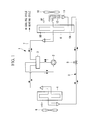
- Fig. 1 shows a refrigerant circuit of the heat exchanger system according to the first embodiment of the present invention.
- the heat exchanger system 1 of the present embodiment includes a closed cycle refrigerant circuit (refrigeration cycle) 8, in which a compressor 2, a four way switching valve 3, a use side heat exchanger (indoor-side heat exchanger) 4, an electrically-driven type expansion valve (EEV) 5, a heat-source side heat exchanger (outside heat exchanger) 6 are connected in this order via the refrigerant pipe 7.
- a non-azeotropic refrigerant mixture having so-called temperature glide for example, R407C, a refrigerant mixture of R32 and R125, etc.
- Each of the use side heat exchanger 4 and the heat-source side heat exchanger 6 is configured so that the refrigerant is distributed and circulated in a plurality of circuits, and a use side fan 9 and a heat source side fan 10 that circulate air to each heat exchanger is provided for each heat exchanger.
- the refrigerant discharged from the compressor 2 flows in a cooling cycle in which the refrigerant circulates in the heat-source side heat exchanger 6, the expansion valve (EEV) 5, the use side heat exchanger 4, the four way switching valve 3, and the compressor 2 in this order via the four way switching valve 3 as shown in the continuous line arrow, to thereby perform the cooling operation.
- the use side heat exchanger 4 that serves as an evaporator absorbs heat from the interior air blown by the use side fan 9, and radiates the heat by the heat-source side heat exchanger 6 to the outdoor air, thereby performing the cooling operation.
- the refrigerant discharged from the compressor 2 flows in the heat cycle in which the refrigerant circulates, via the four way switching valve 3, the use side heat exchanger 4, the expansion valve (EEV) 5, the heat-source side heat exchanger 6, the four way switching valve 3, and the compressor 2 in this order as indicated by the dashed lines arrow, to perform the heating operation.
- the heat-source side heat exchanger 6 serves as an evaporator, absorbs heat from the outdoor air blown by the heat source side fan 10 and radiate the heat to the interior air side by the use side heat exchanger 4 to perform the heating operation.
- the heat-source side heat exchanger 6 serving as an evaporator in a heat cycle is configured in the following manner. As shown in Fig. 1 , a part of the refrigerant circuit 6A extends within the heat exchanger 6 in the inlet portion, and a part of the refrigerant circuit continuing from that part extends out of the heat exchanger 6 and then connects to a plurality of circuits (refrigerant circuits) 6B via a distributor 11 and a plurality of distribution capillary tube 12. The refrigerant is then circulated within the heat exchanger 6.
- the present embodiment has a circuit configuration in which, a part of the refrigerant circuit 6A extends within the heat exchanger 6, and a part of the refrigerant circuit continuing from the heat exchanger 6 and reconnecting to a plurality of circuits (refrigerant circuits) 6B via a distributor 11 and a plurality of distribution capillary tube 12, and the refrigerant is then circulated in the heat exchanger 6.
- the amount of flow reduction of the refrigerant is borne by both of the expansion valve (EEV) 5 and the distribution capillary tube 12 in a heat cycle in which the refrigerant discharged from the compressor 2 circulates in the four way switching valve 3, the use side heat exchanger 4, the expansion valve (EEV) 5, the heat-source side heat exchanger 6, the four way switching valve 3 and the compressor 2 in this order.
- EAV expansion valve
- the expansion valve (EEV) 5 the heat-source side heat exchanger 6
- the four way switching valve 3 the compressor 2 in this order.
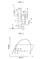
- Mollier diagram of Fig. 3 illustrates this. That is, the reduction process (expansion process) of the refrigerant is borne by both of the expansion valve (EEV) 5 and the distribution capillary tube 12.
- the flow of the refrigerant, comparatively loosely regulated by the expansion valve (EEV) 5 in the refrigerant circuit 6A, is circulated in the heat source side in the heat exchanger 6. Then the refrigerant flows outside of the heat exchanger 6, and the refrigerant flow is then regulated by the distribution capillary tube 12 to circulate in the plurality of circuits 6B.
- the temperature of the refrigerant that normally becomes the lowest temperature in the inlet portion of the heat-source side heat exchanger 6 by reducing the refrigerant flow to the point "a” by the expansion valve (EEV) 5, is set to be comparatively high by regulating the amount of refrigerant flow to point "b" to supply the refrigerant to the heat-source side heat exchanger 6 via a reduction process as in (A).
- the present embodiment differs from the above-described first embodiment in that a parallel circuit of a solenoid valve and a capillary tube is provided in the inlet side of the distribution capillary tube 12. Other points are same as the first embodiment and the redundant explanations will be omitted.
- the heat-source side heat exchanger (outside heat exchanger) 6 is configured so that a parallel circuit 16 of the solenoid valve 13, the check valve 14 and the capillary tube 15 are connected in a part that is the inlet side of the distributor 11 and a plurality of distribution capillary tubes 12 in the heat cycle.
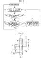
- the solenoid valve 13 is controlled in the manner as shown in Fig. 4 .
- the solenoid valve 13 is normally in an open state.
- step S1 the degree of superheat of the expansion valve (EEV) 5 is controlled.
- the control of degree of superheat is performed in such a manner as to determine whether the degree of superheat of the refrigerant at an outlet of the heat-source side heat exchanger 6 is the target degree of superheat in step S2, and if NO, the process returns to step S1 and adjust the opening degree of the expansion valve (EEV) 5.
- step S3 When the degree of superheat of the refrigerant at the outlet of the heat-source side heat exchanger 6 becomes the target degree of superheat (degree of superheat of the refrigerant at the outlet equals to the target degree of superheat) and it is determined as YES, the process proceeds to step S3.
- step S3 it is determined whether the refrigerant temperature at the inlet of the heat-source side heat exchanger 6 detected by the thermal sensor 17 is X degrees centigrade, which is the pre-set temperature, or greater.
- the temperature is X degrees centigrade, which is the pre-set temperature, or greater, it is determined as YES, and determined that the allotment of reduction is appropriate, and the process returns to the start point while the solenoid valve 13 is kept in the open state.
- step S4 since the solenoid valve 13 is closed, the refrigerant is circulated in the distributor 11 via the capillary tube 15. Therefore, the proportion of amount of reduction by the capillary tubes 12, 15 becomes large.
- the degree of superheat of the refrigerant at the outlet of the heat-source side heat exchanger 6 becomes large.
- the opening degree of the expansion valve (EEV) 5 becomes large by controlling the degree of superheat, as shown in the Mollier diagram of Fig. 3 , the reduction of the expansion valve (EEV) 5 is brought down to the point "c", and the proportion of allotment of the amounts of flow reduction between the expansion valve (EEV) 5 and the capillary tubes 12, 15 are adjusted.
- the refrigerant is supplied to the heat-source side heat exchanger 6 via the reduction process as in (B), and the refrigerant temperature at the inlet of the heat-source side heat exchanger 6 is to be adjusted to be the pre-set temperature, X degrees centigrade, , or greater.
- the present embodiment accordingly, has the following configuration.
- the parallel circuit 16 of the solenoid valve 13 and the capillary tube 15 is provided in the inlet side of the distribution capillary tube 12.
- the solenoid valve 13 is opened and closed depending on the operational state to control whether the refrigerant is flowed through the solenoid valve 13, or the refrigerant is flowed through the capillary tube 15.
- the proportion of allotment of the amount of flow reduction by the capillary tubes 12, 15, with respect to that of the expansion valve (EEV) 5 is adjustable by varying the amount of flow reduction by the capillary tubes 12, 15.
- the refrigerant temperature at the inlet of the heat-source side heat exchanger 6 can be appropriately adjusted, and it is possible to improve the heat exchanger performance (evaporator performance) while reliably suppressing local frosting near the inlet of the heat-source side heat exchanger 6.
- the above-stated embodiment can adjust the refrigerant temperature at the inlet of the heat-source side heat exchanger 6 to the pre-set temperature or greater, by adjusting the proportion of allotment by the capillary tubes 12, 15 with respect to that of the expansion valve (EEV) 5, of amount of flow reduction, by closing the solenoid valve 13 to flow the refrigerant by way of the capillary tube 15, increasing the proportion of amount of reduction by the capillary tubes 12, 15.
- EEV expansion valve
- the present embodiment differs from the above-described first and second embodiments in that the refrigerant flow in the heat-source side heat exchanger 6, is made to be the counter flow against the air flow from the heat source side fan 10 as described above.
- Other configurations are same as the first and second embodiments, and the redundant explanations are omitted.
- the present embodiment is configured such that, as shown in Fig. 5 , in a heat cycle, refrigerant circuit 6A and a plurality of circuits 6B in the heat-source side heat exchanger (outside heat exchanger) 6, is disposed so that the refrigerant flows from the downstream side to the upstream side with respect to the air flow AF from the heat source side fan 10. Consequently, the refrigerant flow is in a counter flow (countercurrent) with respect to the air flow AF.
- the present embodiment differs from the above-described first through third embodiments in that a small heat exchanger 18 is provided instead of the refrigerant circuit 6A of the heat-source side heat exchanger 6.
- Other configurations are same as the first third embodiments, and the redundant explanations are omitted.
- the present embodiment is configured so that, as shown in Fig. 6 , in the refrigerant inlet side of the heat-source side heat exchanger (outside heat exchanger) 6 in a heat cycle, a small heat exchanger 18 having a volume smaller than the heat-source side heat exchanger 6 is provided in place of the refrigerant circuit 6A provided in the first to third embodiments.
- the present embodiment is configured such that the distribution capillary tube 12 is connected to the outlet side of the small heat exchanger 18, and the other end of the distribution capillary tube 12 is connected to a plurality of circuits 6B in the heat-source side heat exchanger 6. Further, the small heat exchanger 18 is disposed in the downstream side of the heat-source side heat exchanger 6 in the air flow AF blown from the heat source side fan 10, and the refrigerant flow in the heat-source side heat exchanger 6 is in a counter flow (countercurrent) with respect to the air flow AF described above.
- the small heat exchanger 18 not only it has a smaller capacity than the heat-source side heat exchanger 6, but the fin pitch thereof is coarse or the fin width thereof is large, and the temperature at the end portion of the fin becomes high. As shown in Fig. 7 , the small heat exchanger 18 is disposed such that its portion of minimum temperature is located in a domain which is in the downstream side of the heat-source side heat exchanger 6 with respect to the air flow AF blown by the heat source side fan 10, wherein the domain is apart from the end portion of the heat source side fun and the speed distribution of air flow is large.
- the small heat exchanger 18, having a volume smaller than the heat-source side heat exchanger 6, is installed in the refrigerant inlet side of the heat-source side heat exchanger 6 serving as an evaporator in a heat cycle. Therefore, in a heat cycle, heat is exchanged between the refrigerant of the lowest temperature and the air in the small heat exchanger 18; it is thus possible to supply the refrigerant after the temperature is raised in the heat-source side heat exchanger 6. Accordingly, it is possible to improve the heat exchanger performance (evaporator performance) while reliably suppressing frosting in the heat-source side heat exchanger 6.
- the small heat exchanger 18 has a coarse fin pitch or a large fin width and the temperature at the end portion of the fin is higher than that in the heat-source side heat exchanger 6. Therefore, in a heat cycle, it is possible to raise the temperature of the refrigerant of the lowest temperature by heat exchange in the small heat exchanger 18, while suppressing frosting on the small heat exchanger 18 itself, by reducing the amount of heat exchange by the fin configuration and avoiding frosting on the fin. Accordingly, it is possible to suppress frosting on both small heat exchanger 18 and heat-source side heat exchanger 6, and stably continue heating operation.
- the above-described small heat exchanger 18 is installed so that the portion of the minimum temperature is located in the range in the downstream side of the heat-source side heat exchanger 6, with respect to the air flow AF blown by the heat source side fan 10, and in the domain where the speed distribution of air flow is large. Therefore, it is possible to make frosting less likely occur by heating the small heat exchanger 18 through which the refrigerant with the lowest-temperature circulates. This is done by having the air flow pass through the heat-source side heat exchanger 6 to decrease moisture level with a large speed distribution of air flow. Accordingly, it becomes possible to further stabilize the heating operation by reliably suppressing the frosting on both the small heat exchanger 18 and the heat-source side heat exchanger 6.
- the present invention is not limited to the above-described embodiments, and can be modified within the scope of the gist of the present invention, and appropriate modifications may be possible.
- the use side heat exchanger (indoor-side heat exchanger) 4 is the refrigerant-air heat exchanger
- the use side heat exchanger may be a refrigerant-water heat exchanger or the like. Accordingly, the heat exchanger system of the present invention can be widely applied, not only to air conditioners or freezer, but also to chiller or water heaters.
Landscapes
- Engineering & Computer Science (AREA)
- Physics & Mathematics (AREA)
- Mechanical Engineering (AREA)
- Thermal Sciences (AREA)
- General Engineering & Computer Science (AREA)
- Compression-Type Refrigeration Machines With Reversible Cycles (AREA)
- Heat-Exchange Devices With Radiators And Conduit Assemblies (AREA)
Applications Claiming Priority (1)
| Application Number | Priority Date | Filing Date | Title |
|---|---|---|---|
| JP2012128839A JP6045204B2 (ja) | 2012-06-06 | 2012-06-06 | 熱交換システム |
Publications (2)
| Publication Number | Publication Date |
|---|---|
| EP2672205A2 true EP2672205A2 (de) | 2013-12-11 |
| EP2672205A3 EP2672205A3 (de) | 2014-03-12 |
Family
ID=48539036
Family Applications (1)
| Application Number | Title | Priority Date | Filing Date |
|---|---|---|---|
| EP13170506.3A Withdrawn EP2672205A3 (de) | 2012-06-06 | 2013-06-04 | Wärmetauschersystem |
Country Status (2)
| Country | Link |
|---|---|
| EP (1) | EP2672205A3 (de) |
| JP (1) | JP6045204B2 (de) |
Cited By (3)
| Publication number | Priority date | Publication date | Assignee | Title |
|---|---|---|---|---|
| EP3128263A4 (de) * | 2014-03-07 | 2018-01-10 | Mitsubishi Electric Corporation | Wärmetauscher und klimaanlage |
| US20180010831A1 (en) * | 2016-07-11 | 2018-01-11 | Hill Phoenix, Inc. | Valve and capillary tube system for refrigeration systems |
| WO2023079123A1 (en) * | 2021-11-05 | 2023-05-11 | Maersk Container Industry A/S | Heat exchanger arrangement and method of controlling same |
Families Citing this family (1)
| Publication number | Priority date | Publication date | Assignee | Title |
|---|---|---|---|---|
| CN109458697B (zh) * | 2018-10-31 | 2020-03-17 | 珠海格力电器股份有限公司 | 换热设备化霜控制方法、装置及系统 |
Citations (2)
| Publication number | Priority date | Publication date | Assignee | Title |
|---|---|---|---|---|
| JPH08334274A (ja) | 1995-06-09 | 1996-12-17 | Matsushita Electric Ind Co Ltd | 空気調和機 |
| JP2008256311A (ja) | 2007-04-06 | 2008-10-23 | Daikin Ind Ltd | 空気調和装置 |
Family Cites Families (10)
| Publication number | Priority date | Publication date | Assignee | Title |
|---|---|---|---|---|
| JP3219577B2 (ja) * | 1993-12-17 | 2001-10-15 | 三菱重工業株式会社 | 空気調和機 |
| JPH07190571A (ja) * | 1993-12-24 | 1995-07-28 | Matsushita Electric Ind Co Ltd | 非共沸混合冷媒を用いた冷凍装置 |
| JP3054539B2 (ja) * | 1994-03-29 | 2000-06-19 | 三洋電機株式会社 | 空気調和機 |
| JPH0854149A (ja) * | 1994-08-11 | 1996-02-27 | Matsushita Electric Ind Co Ltd | 冷凍装置 |
| JPH09145187A (ja) * | 1995-11-24 | 1997-06-06 | Hitachi Ltd | 空気調和装置 |
| JPH09257334A (ja) * | 1996-03-26 | 1997-10-03 | Mitsubishi Electric Corp | ヒートポンプ式空気調和装置 |
| JPH09280670A (ja) * | 1996-04-17 | 1997-10-31 | Mitsubishi Electric Corp | 熱交換器 |
| JP2000249479A (ja) * | 1999-02-26 | 2000-09-14 | Matsushita Electric Ind Co Ltd | 熱交換器 |
| JP3738760B2 (ja) * | 2002-12-25 | 2006-01-25 | 松下電器産業株式会社 | 冷凍装置 |
| JP2011163674A (ja) * | 2010-02-10 | 2011-08-25 | Mitsubishi Heavy Ind Ltd | 可逆方向レシーバおよび空気調和機 |
-
2012
- 2012-06-06 JP JP2012128839A patent/JP6045204B2/ja active Active
-
2013
- 2013-06-04 EP EP13170506.3A patent/EP2672205A3/de not_active Withdrawn
Patent Citations (2)
| Publication number | Priority date | Publication date | Assignee | Title |
|---|---|---|---|---|
| JPH08334274A (ja) | 1995-06-09 | 1996-12-17 | Matsushita Electric Ind Co Ltd | 空気調和機 |
| JP2008256311A (ja) | 2007-04-06 | 2008-10-23 | Daikin Ind Ltd | 空気調和装置 |
Cited By (5)
| Publication number | Priority date | Publication date | Assignee | Title |
|---|---|---|---|---|
| EP3128263A4 (de) * | 2014-03-07 | 2018-01-10 | Mitsubishi Electric Corporation | Wärmetauscher und klimaanlage |
| US20180010831A1 (en) * | 2016-07-11 | 2018-01-11 | Hill Phoenix, Inc. | Valve and capillary tube system for refrigeration systems |
| US11029066B2 (en) * | 2016-07-11 | 2021-06-08 | Hill Phoenix, Inc. | Valve and capillary tube system for refrigeration systems |
| US11892210B2 (en) | 2016-07-11 | 2024-02-06 | Hill Phoenix, Inc. | Valve and capillary tube system for refrigeration systems |
| WO2023079123A1 (en) * | 2021-11-05 | 2023-05-11 | Maersk Container Industry A/S | Heat exchanger arrangement and method of controlling same |
Also Published As
| Publication number | Publication date |
|---|---|
| JP2013253726A (ja) | 2013-12-19 |
| JP6045204B2 (ja) | 2016-12-14 |
| EP2672205A3 (de) | 2014-03-12 |
Similar Documents
| Publication | Publication Date | Title |
|---|---|---|
| EP3059515B1 (de) | Klimaanlage | |
| EP3521732B1 (de) | Klimaanlage | |
| US10006647B2 (en) | Air conditioning system with distributor for a plurality of indoor units | |
| EP3147587B1 (de) | Klimatierungsvorrichtung | |
| JP6781034B2 (ja) | 冷媒回路システムおよび冷媒回路システムの制御方法 | |
| JP5404489B2 (ja) | 空気調和機 | |
| JP2019045034A5 (de) | ||
| EP2990737B1 (de) | Heisswasserversorgungsvorrichtung | |
| EP3516305B1 (de) | Klimaanlage | |
| CN107477930B (zh) | 空调系统、空调装置及其控制方法和控制装置 | |
| US10281184B2 (en) | Air conditioner | |
| CN106969547B (zh) | 蒸发器冷媒流量分配控制方法和控制装置以及空调器系统 | |
| CN105004114A (zh) | 空调器及其除霜方法 | |
| EP2672205A2 (de) | Wärmetauschersystem | |
| CN110567128A (zh) | 一种多联机空调及其控制方法 | |
| EP3859245B1 (de) | Wärmepumpenvorrichtung | |
| EP2857773A1 (de) | Klimaanlage | |
| JP2016133257A (ja) | 空気調和装置 | |
| CN116018486B (zh) | 热泵装置及其控制方法 | |
| EP3062041A1 (de) | Kühlvorrichtung | |
| CN204084662U (zh) | 空调 | |
| US9546806B2 (en) | Air conditioner | |
| US11353234B2 (en) | Air conditioning system | |
| JP2013253726A5 (de) | ||
| EP4160107A1 (de) | Kältekreislaufvorrichtung |
Legal Events
| Date | Code | Title | Description |
|---|---|---|---|
| PUAI | Public reference made under article 153(3) epc to a published international application that has entered the european phase |
Free format text: ORIGINAL CODE: 0009012 |
|
| AK | Designated contracting states |
Kind code of ref document: A2 Designated state(s): AL AT BE BG CH CY CZ DE DK EE ES FI FR GB GR HR HU IE IS IT LI LT LU LV MC MK MT NL NO PL PT RO RS SE SI SK SM TR |
|
| AX | Request for extension of the european patent |
Extension state: BA ME |
|
| PUAL | Search report despatched |
Free format text: ORIGINAL CODE: 0009013 |
|
| AK | Designated contracting states |
Kind code of ref document: A3 Designated state(s): AL AT BE BG CH CY CZ DE DK EE ES FI FR GB GR HR HU IE IS IT LI LT LU LV MC MK MT NL NO PL PT RO RS SE SI SK SM TR |
|
| AX | Request for extension of the european patent |
Extension state: BA ME |
|
| RIC1 | Information provided on ipc code assigned before grant |
Ipc: F25B 9/00 20060101AFI20140205BHEP Ipc: F25B 49/02 20060101ALI20140205BHEP Ipc: F25B 13/00 20060101ALI20140205BHEP Ipc: F25B 39/02 20060101ALI20140205BHEP |
|
| 17P | Request for examination filed |
Effective date: 20140820 |
|
| RBV | Designated contracting states (corrected) |
Designated state(s): AL AT BE BG CH CY CZ DE DK EE ES FI FR GB GR HR HU IE IS IT LI LT LU LV MC MK MT NL NO PL PT RO RS SE SI SK SM TR |
|
| STAA | Information on the status of an ep patent application or granted ep patent |
Free format text: STATUS: EXAMINATION IS IN PROGRESS |
|
| 17Q | First examination report despatched |
Effective date: 20170616 |
|
| RAP1 | Party data changed (applicant data changed or rights of an application transferred) |
Owner name: MITSUBISHI HEAVY INDUSTRIES THERMAL SYSTEMS, LTD. |
|
| STAA | Information on the status of an ep patent application or granted ep patent |
Free format text: STATUS: THE APPLICATION IS DEEMED TO BE WITHDRAWN |
|
| 18D | Application deemed to be withdrawn |
Effective date: 20200806 |