EP2672782B1 - Mikrowellenofen und Verfahren zur Steuerung der Einspeisung davon - Google Patents
Mikrowellenofen und Verfahren zur Steuerung der Einspeisung davon Download PDFInfo
- Publication number
- EP2672782B1 EP2672782B1 EP13170693.9A EP13170693A EP2672782B1 EP 2672782 B1 EP2672782 B1 EP 2672782B1 EP 13170693 A EP13170693 A EP 13170693A EP 2672782 B1 EP2672782 B1 EP 2672782B1
- Authority
- EP
- European Patent Office
- Prior art keywords
- cooking
- dial
- mode
- microwave oven
- cooking mode
- Prior art date
- Legal status (The legal status is an assumption and is not a legal conclusion. Google has not performed a legal analysis and makes no representation as to the accuracy of the status listed.)
- Not-in-force
Links
Images



Classifications
-
- F—MECHANICAL ENGINEERING; LIGHTING; HEATING; WEAPONS; BLASTING
- F24—HEATING; RANGES; VENTILATING
- F24C—DOMESTIC STOVES OR RANGES ; DETAILS OF DOMESTIC STOVES OR RANGES, OF GENERAL APPLICATION
- F24C7/00—Stoves or ranges heated by electric energy
- F24C7/08—Arrangement or mounting of control or safety devices
-
- H—ELECTRICITY
- H05—ELECTRIC TECHNIQUES NOT OTHERWISE PROVIDED FOR
- H05B—ELECTRIC HEATING; ELECTRIC LIGHT SOURCES NOT OTHERWISE PROVIDED FOR; CIRCUIT ARRANGEMENTS FOR ELECTRIC LIGHT SOURCES, IN GENERAL
- H05B6/00—Heating by electric, magnetic or electromagnetic fields
- H05B6/64—Heating using microwaves
- H05B6/6435—Aspects relating to the user interface of the microwave heating apparatus
-
- F—MECHANICAL ENGINEERING; LIGHTING; HEATING; WEAPONS; BLASTING
- F24—HEATING; RANGES; VENTILATING
- F24C—DOMESTIC STOVES OR RANGES ; DETAILS OF DOMESTIC STOVES OR RANGES, OF GENERAL APPLICATION
- F24C7/00—Stoves or ranges heated by electric energy
Definitions
- the present invention relates to a microwave oven that may conveniently input automatic or manual cooking using one dial.
- a cooking device such as a microwave oven, is a device in which microwaves of about 2,450 MHz generated by applying high-voltage electricity to a magnetron that is a highfrequency oscillation tube vibrate water molecules contained in a cooking object and the cooking object is rapidly heated by frictional heat generated by this vibration.
- a user selects a cooking mode between a manual cooking mode in which a cooking time needs to be directly input and an automatic cooking mode in which a state of the cooking object is detected during a cooking operation using a cooking menu in which a cooking time is preset, or an appropriate cooking time is automatically calculated using the result of detection by one or more sensors, such as a humidity sensor, a gas sensor, or a temperature sensor. Subsequently, a setting value of the selected cooking mode (specifically, a detailed cooking function of each cooking mode) should be set.
- a mode key is pressed or a mode dial is manipulated so as to select an automatic or manual cooking mode, and then a separately-provided setting dial is manipulated to set a detailed cooking function (in case of the automatic cooking mode, a cooking item and in case of the manual cooking mode, a cooking time) of the selected cooking mode.
- the cooking device should provide a mode dial (or mode key) for selecting a cooking mode and a separate setting dial for setting a detailed cooking function of each cooking mode so as to input automatic or manual cooking.
- a mode dial or mode key
- a separate setting dial for setting a detailed cooking function of each cooking mode so as to input automatic or manual cooking.
- a user who is not accustomed to the cooking device has a difficulty of manipulation regarding which dial is manipulated to select desired cooking, and even in case of a user who is accustomed to the cooking device, there are inconveniences of manipulation regarding that a dial need to be moved whenever the user selects desired cooking.
- a microwave oven may set an automatic or manual cooking mode and a detailed cooking function of each cooking mode using only one dial and a method for controlling input of the microwave oven.
- a microwave oven including: one dial that is rotated in one direction to select a cooking mode from a plurality of cooking modes and is rotated in both directions to set a detailed cooking function of the selected cooking mode; and a display unit that displays a cooking mode selected according to rotation manipulation of the dial and a detailed cooking function of each cooking mode.
- the cooking mode may include an automatic cooking mode and a manual cooking mode.
- the one direction may include a first manipulation direction in which the dial is rotated to the left and a second manipulation direction in which the dial is rotated to the right.
- the display unit may display an initial screen of the automatic cooking mode and then may display one among the plurality of cooking items that vary according to rotation manipulation of the dial in both right and left directions.
- the dial may select a manual cooking mode according to rotation manipulation in the second manipulation direction and may set a cooking time according to rotation manipulation in both right and left directions in a state in which the manual cooking mode is selected.
- the display unit may display an initial screen of the manual cooking mode and then may display the cooking time that varies according to rotation manipulation of the dial in both left and right directions.
- the microwave oven may further include a controller that controls a cooking operation so as to perform a detailed cooking function of a cooking mode selected according to rotation manipulation of the dial.
- a method for controlling input of a microwave oven that inputs automatic cooking or manual cooking using one dial including: selecting a predetermined cooking mode by rotating the dial in one direction; and setting a detailed cooking function of the selected cooking mode by rotating the dial in both directions.
- the method may further include displaying a cooking mode selected according to rotation manipulation of the dial and a detailed cooking function of each cooking mode using a display unit.
- a microwave oven including one dial that is rotated in one of a first direction and a second direction to select a cooking mode from a first cooking mode and a second cooking mode, and that is rotated in both left and right directions to set a cooking function of the selected cooking mode; and a display unit that displays the cooking mode selected according to rotation manipulation of the dial and a cooking function of each cooking mode, wherein the first direction is a first manipulation direction in which the dial is rotated to the left and a second direction is a second manipulation direction in which the one dial is rotated to the right, and wherein the cooking function of cooking mode selected by rotating the one dial in the first direction is different from the cooking function of cooking mode selected by rotating the one dial in the second direction.
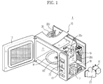
- FIG. 1 is an exploded perspective view of a microwave oven according to an embodiment.
- a microwave oven 1 is partitioned off into a box-shaped main body 10 that includes the exterior, a cooking chamber m that is installed in the main body 10 so as to cook a cooking object, and a machine chamber 12 in which various electric components are embedded.
- a front side of the cooking chamber 11 is opened so that the cooking object may be accommodated in the cooking chamber 11, a door 13 is installed at the open front side of the cooking chamber 11 so as to open/close the cooking chamber 11, and a turntable 14 on which the cooking object is mounted is rotatably installed in the cooking chamber 11.
- various electric components such as a general magnetron 16 that supplies a high frequency into the cooking chamber 11, a high-voltage transformer 17 and a high-voltage capacitor 18 that supply a high voltage to the magnetron 16, a cooling fan 19 that cools various electric components including the magnetron 16 installed in the machine chamber 12, and an air guide duct 20 that guides air discharged from the machine chamber 12, are installed in the machine chamber 12.
- a humidity sensor 30 that senses humidity of air inside the cooking chamber 11 is installed at one side of the exhaust holes 20c and detects a cooking condition (a cooking state of the cooking object) of the microwave oven 1.
- the humidity sensor 30 is installed to contact air discharged from the cooking chamber 11 via the exhaust holes 20c and detects moisture contained in water vapor generated in the cooking object when a cooking operation of the microwave oven 1 is performed.
- the humidity sensor 30 is installed to detect a cooking condition when automatic cooking of the microwave oven 1 is performed.
- embodiments are not limited thereto, and a gas sensor or temperature sensor may also be installed so as to detect the cooking condition of the microwave oven 1.
- a control panel 21 is installed at a front side of the machine chamber 12.
- the control panel 21 selects a cooking mode that a user wants and a detailed cooking function of each cooking mode and displays the selected cooking function and an operating state.
- FIG. 2 illustrates the control panel of the microwave oven 1 of FIG. 1 .
- buttons 60 to which a user's manipulation instruction is input so as to control the operation of the microwave oven 1, one dial 70 for selecting an automatic or manual cooking mode and for setting a detailed cooking function of the selected cooking mode, and a display unit 80 that displays the operating state of the microwave oven 1 and a user's manipulation state, are disposed on a control panel 21.
- the dial 70 is positioned in the center of the control panel 21 and may be manipulated to be rotated to the right (clockwise) and to the left (counterclockwise).
- the dial 70 has a first manipulation direction in which the dial 70 is rotated to the left and a second manipulation direction in which the dial 70 is rotated to the right.
- the dial 70 is manipulated to be rotated in the first manipulation direction or the second manipulation direction in a standby mode and sets an automatic or manual cooking condition.
- an automatic cooking mode Express Menu is selected.
- a manual cooking mode Microwave +30 Sec is selected.
- the automatic or manual cooking mode is selected according to one-click rotation manipulation in the first manipulation direction or the second manipulation direction regardless of the position of the dial 70.
- Embodiments are not limited to a manual cooking mode Microwave +30 Sec.
- a manual cooking mode may be Microwave+60 Sec or some other time period.
- a direction in which the automatic cooking mode or the manual cooking mode is selected may be reversely configured according to rotation manipulation of the dial 70 in the first manipulation direction or the second manipulation direction. That is, when the dial 70 is manipulated to be rotated by one click in the first manipulation direction in the standby mode state, the manual cooking mode Microwave +30 Sec may be selected, and when the dial 70 is manipulated to be rotated by one click in the second manipulation direction in the standby mode state, the automatic cooking mode Express Menu may be selected.
- the automatic or manual cooking mode that is selected as the dial 70 is manipulated to be rotated to the right or to the left may be displayed on the display unit 80, and the user may check the selected cooking mode through the display unit 80.
- the user After selecting the automatic or manual cooking mode by manipulating the dial 70 to be rotated in the first manipulation direction or the second manipulation direction, the user manipulates to freely rotate the dial 70 to the right and to the left, i.e., in both directions so as to set a detailed cooking function of the automatic or manual cooking mode.
- the automatic cooking mode Express Menu is selected.
- a plurality of cooking items for example, approximately 9 cooking menus
- the varying cooking item is displayed on the display unit 80, and the user may set a desired cooking item while checking the cooking item displayed on the display unit 80.
- the manual cooking mode Microwave +30 Sec is selected.
- a cooking time varies. In this case, the varying cooking time is displayed on the display unit 80, and the user sets a desired cooking time while checking the cooking time displayed on the display unit 80.
- FIG. 3 is a view of control configuration of the microwave oven 1 of FIG. 1 .
- the microwave oven 1 includes the display unit 80, a sensor unit 100, an input unit 110, a controller 120, a magnetron driving unit 130, a motor driving unit 140, and a fan driving unit 150.
- the display unit 80 is disposed on the control panel 21 and displays the operating state of the microwave oven 1 and the user's manipulation state according to a display control signal of the controller 120.
- the sensor unit 100 detects a varying cooking condition, i.e., the state of the cooking object of the cooking chamber 11 when automatic cooking of the microwave oven 1 is performed.
- the sensor unit 100 refers to at least one among the humidity sensor 30 that detects the humidity of air inside the cooking chamber 11, a gas sensor 40 that detects the amount of gas inside the cooking chamber 11, and a temperature sensor 50 that detects the temperature inside the cooking chamber 11.
- the sensors 30, 40, and 50 are installed at one side of the exhaust holes 20c so as to contact air discharged from the cooking chamber 11.
- the input unit 110 includes the plurality of buttons 60 and one dial 70 that are disposed on the control panel 21 so that the user may input desired cooking information (a cooking time, a cooking menu, automatic cooking using a sensor, start/stop cooking, and the like) to the controller 120.
- desired cooking information a cooking time, a cooking menu, automatic cooking using a sensor, start/stop cooking, and the like
- the controller 120 may be a microcomputer that controls components of the microwave oven 1 according to manipulation information input from the input unit 110.
- the controller 120 controls an output of microwaves by determining the state of the cooking object based on a sensor output value input from the sensor unit 100.
- the magnetron driving unit 130 includes a relay that controls driving of the magnetron 16 so as to generate microwaves according to a control signal of the controller 120.
- the motor driving unit 140 drives a motor 141 so as to rotate the turntable 14 according to the control signal of the controller 120.
- the fan driving unit 150 operates the cooling fan 19 that cools the machine chamber 12 according to the control signal of the controller 120 to ventilate the inside of the cooking chamber 11.
- the fan driving unit 150 cools the sensors 30, 40, and 50 using a ventilation air current so that the sensors 30, 40, and 50 may have stable operating characteristics.
- microwave oven 1 illustrated in FIG. 1 , operations of a method for controlling input of the microwave oven 1, and effects thereof will be described.
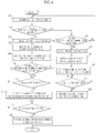
- FIG. 4 is a flowchart illustrating an operation of a dial input control algorithm in the microwave oven 1 of FIG. 1
- FIG. 5 is a view of automatic cooking input of the microwave oven 1 of FIG. 1
- FIG. 6 is a view of manual cooking input of the microwave oven 1 of FIG. 1 .
- the user puts the cooking object on the turntable 14 inside the cooking chamber 11 and manipulates the dial 70 disposed on the control panel 21 to be rotated, thereby inputting automatic or manual cooking (200).
- a method of inputting automatic or manual cooking by manipulating the dial 70 to be rotated is as follows.
- the user manipulates the dial 70 to be rotated by one click in the first manipulation direction (specifically, to the left) in the standby mode state so as to select an automatic cooking mode.
- the controller 120 determines whether the dial 70 is rotated in the first manipulation direction (202).
- the controller 120 determines that the user has selected the automatic cooking mode (204). Then, the controller 120 displays an initial screen of the automatic cooking mode on the display unit 80 disposed on an upper part of the control panel 21, as illustrated in FIG. 5 (206).
- the user may check that the automatic cooking mode has been selected, through the initial screen of the automatic cooking mode displayed on the display unit 80.
- the user manipulates the dial 70 to be freely rotated to the right and to the left, i.e., in both directions in a state in which the automatic cooking mode has been selected, thereby setting a cooking item of the automatic cooking mode (208).
- the cooking item of the automatic cooking mode is a detailed cooking function in which a cooking condition (a cooking time and output of microwaves) is automatically detected using a cooking menu in which a cooking time is preset, or the humidity sensor 30, the gas sensor 40, and the temperature sensor 50.
- a plurality of (such as 9) cooking items corresponding to the detailed cooking function of the automatic cooking mode are stored in the controller 120 in advance, and the user sets a desired cooking item among the plurality of cooking items stored.
- the cooking item that varies as the user manipulates the dial 70 to be rotated to the right and to the left, is displayed on the display unit 80, and the user sets a desired cooking item while checking the cooking item displayed on the display unit 80.
- the controller 120 determines whether the set cooking item is a cooking item, of which the number of servings need to be input, (a cooking item in which the number of cooking objects or the amount of a cooking object is set, for example, a cooking item in which the number of cooking objects, such as one potato, two potatoes, and the like) (210).
- the controller 120 controls the components of the microwave oven 1 during a cooking time of the set cooking item, thereby performing a cooking operation (218).
- the user manipulates the dial 70 to be rotated by one click in the second manipulation direction (specifically, to the right) in the standby mode state so as to select a manual cooking mode.
- the controller 120 needs to determine whether the dial 70 is rotated in the second manipulation direction.
- the controller 120 determines whether the dial 70 is rotated in the second manipulation direction (302).
- the controller 120 determines that the user has selected the manual cooking mode (304). Then, the controller 120 displays an initial screen of the manual cooking mode on the display unit 80, as illustrated in FIG. 6 (306).
- the user may check that the manual cooking mode has been selected, through the initial screen of the manual cooking mode displayed on the display unit 80.
- the user manipulates the dial 70 to be freely rotated to the right and to the left, i.e., in both directions in a state in which the manual cooking mode is selected, thereby setting a cooking time of the manual cooking mode (308).
- the cooking time of the manual cooking mode is input by the user according to the condition of a cooking object, i.e., the type, the weight, or the size of the cooking object.
- the cooking time that varies as the user manipulates the dial 70 to be rotated to the right and to the left, is displayed on the display unit 80, as illustrated in FIG. 6 , and the user sets a desired cooking time while checking the cooking time displayed on the display unit 80.
- the controller 120 controls the components of the microwave oven 1 during the set cooking time, thereby performing a cooking operation (312).
- an automatic or manual cooking mode may be selected using one dial and a detailed cooking function of the selected cooking mode may be set, so that the number of devices for input can be reduced and manipulation performance of both a user who is not accustomed to the microwave oven and a user who is accustomed to the microwave oven can be improved.
Landscapes
- Engineering & Computer Science (AREA)
- Human Computer Interaction (AREA)
- Physics & Mathematics (AREA)
- Electromagnetism (AREA)
- Chemical & Material Sciences (AREA)
- Combustion & Propulsion (AREA)
- Mechanical Engineering (AREA)
- General Engineering & Computer Science (AREA)
- Electric Ovens (AREA)
Claims (7)
- Mikrowellenherd, der Folgendes umfasst:einen Stellknopf (70), der in einer ersten Richtung drehbar ist, um einen automatischen Garmodus auszuwählen, und in einer zweiten Richtung drehbar ist, um einen manuellen Garmodus auszuwählen, und der nach dem Auswählen eines automatischen Garmodus und eines manuellen Garmodus sowohl in einer ersten als auch in einer zweiten Richtung drehbar ist, um einen Parameter des gewählten Garmodus einzustellen; undeine Anzeigeeinheit (80), die Folgendes anzeigt: den Garmodus, der gemäß der Drehbetätigung des Stellknopfs ausgewählt wurde, und einen Parameter des ausgewählten Garmodus.
- Mikrowellenherd nach Anspruch 1, wobei die erste Richtung eine erste Betätigungsrichtung umfasst, in der der Stellknopf nach links gedreht wird, und die zweite Richtung eine zweite Betätigungsrichtung umfasst, in der der Stellknopf nach rechts gedreht wird.
- Mikrowellenherd nach Anspruch 1 oder Anspruch 2, wobei der Stellknopf eine einzelne Gareinstellung aus einer Mehrzahl von Gareinstellungen gemäß der Drehbetätigung sowohl in die rechte als auch die linke Richtung in einem Zustand einstellt, in dem der automatische Garmodus ausgewählt ist.
- Mikrowellenherd nach Anspruch 3, wobei, wenn der Stellknopf so betätigt wird, dass er in die erste Betätigungsrichtung gedreht wird, die Anzeigeeinheit einen Anfangsbildschirm des automatischen Garmodus und daraufhin eines aus der Mehrzahl von Gareinstellungen anzeigt, die je nach der Drehbetätigung des Stellknopfs sowohl in die rechte als auch die linke Richtung variieren.
- Mikrowellenherd nach Anspruch 2, wobei der Stellknopf eine Garzeit gemäß der Drehbetätigung sowohl in die rechte als auch die linke Richtung in einem Zustand einstellt, in dem der manuelle Garmodus ausgewählt ist.
- Mikrowellenherd nach Anspruch 5, wobei, wenn der Stellknopf so betätigt wird, dass er in die zweite Betätigungsrichtung gedreht wird, die Anzeigeeinheit einen Anfangsbildschirm des manuellen Garmodus und daraufhin die Garzeit anzeigt, die je nach der Drehbetätigung des Stellknopfs sowohl in die rechte als auch die linke Richtung variiert.
- Mikrowellenherd nach einem der vorhergehenden Ansprüche, der ferner eine Steuereinheit umfasst, die einen Garbetrieb steuert, um eine Garfunktion eines Garmodus auszuführen, der gemäß der Drehbetätigung des Stellknopfs ausgewählt wurde.
Applications Claiming Priority (1)
| Application Number | Priority Date | Filing Date | Title |
|---|---|---|---|
| KR1020120060651A KR101920430B1 (ko) | 2012-06-05 | 2012-06-05 | 조리기 및 그 입력 제어방법 |
Publications (2)
| Publication Number | Publication Date |
|---|---|
| EP2672782A1 EP2672782A1 (de) | 2013-12-11 |
| EP2672782B1 true EP2672782B1 (de) | 2016-08-10 |
Family
ID=48613431
Family Applications (1)
| Application Number | Title | Priority Date | Filing Date |
|---|---|---|---|
| EP13170693.9A Not-in-force EP2672782B1 (de) | 2012-06-05 | 2013-06-05 | Mikrowellenofen und Verfahren zur Steuerung der Einspeisung davon |
Country Status (4)
| Country | Link |
|---|---|
| US (1) | US20130320003A1 (de) |
| EP (1) | EP2672782B1 (de) |
| KR (1) | KR101920430B1 (de) |
| CN (1) | CN103471142B (de) |
Families Citing this family (4)
| Publication number | Priority date | Publication date | Assignee | Title |
|---|---|---|---|---|
| CN103970429A (zh) * | 2014-05-15 | 2014-08-06 | 佛山市顺德区美的电热电器制造有限公司 | 菜单分区选择的控制方法 |
| US10323846B2 (en) * | 2015-02-05 | 2019-06-18 | William Lawrence Sweet | Safety and convenience system for a gas grill |
| CN104896535B (zh) * | 2015-06-26 | 2017-03-29 | 广东美的厨房电器制造有限公司 | 控制面板及微波烹饪器具 |
| CA3031983C (en) * | 2016-07-29 | 2023-01-03 | Hubert WAT | Microwave oven, system and method of controlling the same using a single input start button |
Family Cites Families (16)
| Publication number | Priority date | Publication date | Assignee | Title |
|---|---|---|---|---|
| US4849595A (en) * | 1985-06-17 | 1989-07-18 | Robertshaw Controls Company | Electrically operated control device and system for a microwave oven |
| GB2288887B (en) * | 1992-02-24 | 1996-02-28 | Toshiba Kk | Heating apparatus |
| US5349164A (en) * | 1992-05-27 | 1994-09-20 | Kabushiki Kaisha Toshiba | Cooking appliance with multifunction knobs |
| GB2267554B (en) * | 1992-06-01 | 1995-08-02 | Matsushita Electric Industrial Co Ltd | Heating apparatus |
| JP2783142B2 (ja) * | 1993-12-27 | 1998-08-06 | タイガー魔法瓶株式会社 | 高周波加熱装置 |
| JPH08303793A (ja) * | 1995-05-10 | 1996-11-22 | Hitachi Home Tec Ltd | 加熱調理器 |
| JP2002535594A (ja) * | 1999-01-13 | 2002-10-22 | ゼネラル・エレクトリック・カンパニイ | 輻射エネルギとマイクロ波エネルギとを使用する組合せオーブン |
| US7030349B1 (en) * | 1999-01-13 | 2006-04-18 | General Electric Company | Combination oven illumination in microwave only cooking mode |
| US6936801B1 (en) * | 1999-08-23 | 2005-08-30 | General Electric Company | Methods and apparatus for rotary dial user entry in an appliance |
| US6987252B2 (en) * | 2001-01-11 | 2006-01-17 | General Electric Company | Speedcooking oven including convection/bake mode and microwave heating |
| US6867399B2 (en) * | 2003-03-14 | 2005-03-15 | General Electric Company | Methods and apparatus for operating a speedcooking oven |
| DE102004046521B3 (de) * | 2004-09-23 | 2006-04-20 | Rational Ag | Verfahren zum Einstellen oder Auswählen eines Arbeitsprogrammes eines Gargeräts und Gargerät zum Durchführen solch eines Verfahrens |
| JP5131969B2 (ja) * | 2007-12-19 | 2013-01-30 | パナソニック株式会社 | 加熱調理器 |
| JP5152971B2 (ja) * | 2007-12-27 | 2013-02-27 | パナソニック株式会社 | 加熱調理器 |
| JP2009156546A (ja) * | 2007-12-27 | 2009-07-16 | Panasonic Corp | 加熱調理器 |
| JP2012052690A (ja) * | 2010-08-31 | 2012-03-15 | Panasonic Corp | 高周波加熱装置 |
-
2012
- 2012-06-05 KR KR1020120060651A patent/KR101920430B1/ko not_active Expired - Fee Related
-
2013
- 2013-05-07 US US13/888,673 patent/US20130320003A1/en not_active Abandoned
- 2013-06-05 EP EP13170693.9A patent/EP2672782B1/de not_active Not-in-force
- 2013-06-05 CN CN201310220557.1A patent/CN103471142B/zh not_active Expired - Fee Related
Also Published As
| Publication number | Publication date |
|---|---|
| KR101920430B1 (ko) | 2018-11-20 |
| KR20130136890A (ko) | 2013-12-13 |
| CN103471142B (zh) | 2017-06-16 |
| US20130320003A1 (en) | 2013-12-05 |
| CN103471142A (zh) | 2013-12-25 |
| EP2672782A1 (de) | 2013-12-11 |
Similar Documents
| Publication | Publication Date | Title |
|---|---|---|
| EP3354989B1 (de) | Kochgerät kommunizierend mit einem endgerät und verfahren zur steuerung des kochgeräts | |
| EP3062206B1 (de) | Betriebsvorrichtung | |
| US4572935A (en) | Cooking apparatus having an initial temperature setting function | |
| EP2672782A1 (de) | Mikrowellenofen und Verfahren zur Steuerung der Einspeisung davon | |
| JP2019027705A (ja) | 加熱調理器 | |
| JP2009008294A (ja) | 加熱調理器 | |
| US20230025683A1 (en) | Optimized cooking method selection | |
| KR100963400B1 (ko) | 조리기기 및 그 제어방법 | |
| KR20210108210A (ko) | 조리기기 | |
| EP1392085A2 (de) | Kochvorrichtung versehen mit Heizelementen | |
| WO2013021459A1 (ja) | 調理器 | |
| WO2012029309A1 (ja) | 高周波加熱装置 | |
| JP2012017882A (ja) | 調理器 | |
| KR20090064497A (ko) | 조리기기 및 그의 제어방법 | |
| JP7821610B2 (ja) | 加熱調理器 | |
| JP5115259B2 (ja) | 加熱装置 | |
| US20250247923A1 (en) | Heating cooker | |
| TWI798466B (zh) | 加熱調理器 | |
| KR100499478B1 (ko) | 토스터 겸용 전자레인지 및 그 제어방법 | |
| KR100191504B1 (ko) | 전자렌지의 회전접시 중량 판별장치 | |
| JP2001235154A (ja) | 加熱調理装置 | |
| JPH0842853A (ja) | 高周波加熱装置の調理メニュー表示装置 | |
| JP2022182223A (ja) | 加熱調理器 | |
| JPH08121779A (ja) | 加熱調理器 | |
| JP2020129462A (ja) | 誘導加熱調理器 |
Legal Events
| Date | Code | Title | Description |
|---|---|---|---|
| PUAI | Public reference made under article 153(3) epc to a published international application that has entered the european phase |
Free format text: ORIGINAL CODE: 0009012 |
|
| AK | Designated contracting states |
Kind code of ref document: A1 Designated state(s): AL AT BE BG CH CY CZ DE DK EE ES FI FR GB GR HR HU IE IS IT LI LT LU LV MC MK MT NL NO PL PT RO RS SE SI SK SM TR |
|
| AX | Request for extension of the european patent |
Extension state: BA ME |
|
| 17P | Request for examination filed |
Effective date: 20140610 |
|
| RBV | Designated contracting states (corrected) |
Designated state(s): AL AT BE BG CH CY CZ DE DK EE ES FI FR GB GR HR HU IE IS IT LI LT LU LV MC MK MT NL NO PL PT RO RS SE SI SK SM TR |
|
| GRAP | Despatch of communication of intention to grant a patent |
Free format text: ORIGINAL CODE: EPIDOSNIGR1 |
|
| RIC1 | Information provided on ipc code assigned before grant |
Ipc: H05B 6/64 20060101AFI20151126BHEP |
|
| INTG | Intention to grant announced |
Effective date: 20151216 |
|
| GRAR | Information related to intention to grant a patent recorded |
Free format text: ORIGINAL CODE: EPIDOSNIGR71 |
|
| GRAS | Grant fee paid |
Free format text: ORIGINAL CODE: EPIDOSNIGR3 |
|
| INTG | Intention to grant announced |
Effective date: 20160428 |
|
| GRAA | (expected) grant |
Free format text: ORIGINAL CODE: 0009210 |
|
| AK | Designated contracting states |
Kind code of ref document: B1 Designated state(s): AL AT BE BG CH CY CZ DE DK EE ES FI FR GB GR HR HU IE IS IT LI LT LU LV MC MK MT NL NO PL PT RO RS SE SI SK SM TR |
|
| REG | Reference to a national code |
Ref country code: GB Ref legal event code: FG4D |
|
| REG | Reference to a national code |
Ref country code: CH Ref legal event code: EP Ref country code: AT Ref legal event code: REF Ref document number: 820095 Country of ref document: AT Kind code of ref document: T Effective date: 20160815 |
|
| REG | Reference to a national code |
Ref country code: IE Ref legal event code: FG4D |
|
| REG | Reference to a national code |
Ref country code: DE Ref legal event code: R096 Ref document number: 602013010200 Country of ref document: DE |
|
| REG | Reference to a national code |
Ref country code: LT Ref legal event code: MG4D |
|
| REG | Reference to a national code |
Ref country code: NL Ref legal event code: MP Effective date: 20160810 |
|
| REG | Reference to a national code |
Ref country code: AT Ref legal event code: MK05 Ref document number: 820095 Country of ref document: AT Kind code of ref document: T Effective date: 20160810 |
|
| PG25 | Lapsed in a contracting state [announced via postgrant information from national office to epo] |
Ref country code: NL Free format text: LAPSE BECAUSE OF FAILURE TO SUBMIT A TRANSLATION OF THE DESCRIPTION OR TO PAY THE FEE WITHIN THE PRESCRIBED TIME-LIMIT Effective date: 20160810 Ref country code: IS Free format text: LAPSE BECAUSE OF FAILURE TO SUBMIT A TRANSLATION OF THE DESCRIPTION OR TO PAY THE FEE WITHIN THE PRESCRIBED TIME-LIMIT Effective date: 20161210 Ref country code: LT Free format text: LAPSE BECAUSE OF FAILURE TO SUBMIT A TRANSLATION OF THE DESCRIPTION OR TO PAY THE FEE WITHIN THE PRESCRIBED TIME-LIMIT Effective date: 20160810 Ref country code: NO Free format text: LAPSE BECAUSE OF FAILURE TO SUBMIT A TRANSLATION OF THE DESCRIPTION OR TO PAY THE FEE WITHIN THE PRESCRIBED TIME-LIMIT Effective date: 20161110 Ref country code: HR Free format text: LAPSE BECAUSE OF FAILURE TO SUBMIT A TRANSLATION OF THE DESCRIPTION OR TO PAY THE FEE WITHIN THE PRESCRIBED TIME-LIMIT Effective date: 20160810 Ref country code: RS Free format text: LAPSE BECAUSE OF FAILURE TO SUBMIT A TRANSLATION OF THE DESCRIPTION OR TO PAY THE FEE WITHIN THE PRESCRIBED TIME-LIMIT Effective date: 20160810 Ref country code: IT Free format text: LAPSE BECAUSE OF FAILURE TO SUBMIT A TRANSLATION OF THE DESCRIPTION OR TO PAY THE FEE WITHIN THE PRESCRIBED TIME-LIMIT Effective date: 20160810 Ref country code: FI Free format text: LAPSE BECAUSE OF FAILURE TO SUBMIT A TRANSLATION OF THE DESCRIPTION OR TO PAY THE FEE WITHIN THE PRESCRIBED TIME-LIMIT Effective date: 20160810 |
|
| PG25 | Lapsed in a contracting state [announced via postgrant information from national office to epo] |
Ref country code: ES Free format text: LAPSE BECAUSE OF FAILURE TO SUBMIT A TRANSLATION OF THE DESCRIPTION OR TO PAY THE FEE WITHIN THE PRESCRIBED TIME-LIMIT Effective date: 20160810 Ref country code: PT Free format text: LAPSE BECAUSE OF FAILURE TO SUBMIT A TRANSLATION OF THE DESCRIPTION OR TO PAY THE FEE WITHIN THE PRESCRIBED TIME-LIMIT Effective date: 20161212 Ref country code: LV Free format text: LAPSE BECAUSE OF FAILURE TO SUBMIT A TRANSLATION OF THE DESCRIPTION OR TO PAY THE FEE WITHIN THE PRESCRIBED TIME-LIMIT Effective date: 20160810 Ref country code: PL Free format text: LAPSE BECAUSE OF FAILURE TO SUBMIT A TRANSLATION OF THE DESCRIPTION OR TO PAY THE FEE WITHIN THE PRESCRIBED TIME-LIMIT Effective date: 20160810 Ref country code: GR Free format text: LAPSE BECAUSE OF FAILURE TO SUBMIT A TRANSLATION OF THE DESCRIPTION OR TO PAY THE FEE WITHIN THE PRESCRIBED TIME-LIMIT Effective date: 20161111 Ref country code: AT Free format text: LAPSE BECAUSE OF FAILURE TO SUBMIT A TRANSLATION OF THE DESCRIPTION OR TO PAY THE FEE WITHIN THE PRESCRIBED TIME-LIMIT Effective date: 20160810 Ref country code: SE Free format text: LAPSE BECAUSE OF FAILURE TO SUBMIT A TRANSLATION OF THE DESCRIPTION OR TO PAY THE FEE WITHIN THE PRESCRIBED TIME-LIMIT Effective date: 20160810 |
|
| PG25 | Lapsed in a contracting state [announced via postgrant information from national office to epo] |
Ref country code: RO Free format text: LAPSE BECAUSE OF FAILURE TO SUBMIT A TRANSLATION OF THE DESCRIPTION OR TO PAY THE FEE WITHIN THE PRESCRIBED TIME-LIMIT Effective date: 20160810 Ref country code: EE Free format text: LAPSE BECAUSE OF FAILURE TO SUBMIT A TRANSLATION OF THE DESCRIPTION OR TO PAY THE FEE WITHIN THE PRESCRIBED TIME-LIMIT Effective date: 20160810 |
|
| REG | Reference to a national code |
Ref country code: DE Ref legal event code: R097 Ref document number: 602013010200 Country of ref document: DE |
|
| PG25 | Lapsed in a contracting state [announced via postgrant information from national office to epo] |
Ref country code: SM Free format text: LAPSE BECAUSE OF FAILURE TO SUBMIT A TRANSLATION OF THE DESCRIPTION OR TO PAY THE FEE WITHIN THE PRESCRIBED TIME-LIMIT Effective date: 20160810 Ref country code: CZ Free format text: LAPSE BECAUSE OF FAILURE TO SUBMIT A TRANSLATION OF THE DESCRIPTION OR TO PAY THE FEE WITHIN THE PRESCRIBED TIME-LIMIT Effective date: 20160810 Ref country code: SK Free format text: LAPSE BECAUSE OF FAILURE TO SUBMIT A TRANSLATION OF THE DESCRIPTION OR TO PAY THE FEE WITHIN THE PRESCRIBED TIME-LIMIT Effective date: 20160810 Ref country code: DK Free format text: LAPSE BECAUSE OF FAILURE TO SUBMIT A TRANSLATION OF THE DESCRIPTION OR TO PAY THE FEE WITHIN THE PRESCRIBED TIME-LIMIT Effective date: 20160810 Ref country code: BG Free format text: LAPSE BECAUSE OF FAILURE TO SUBMIT A TRANSLATION OF THE DESCRIPTION OR TO PAY THE FEE WITHIN THE PRESCRIBED TIME-LIMIT Effective date: 20161110 Ref country code: BE Free format text: LAPSE BECAUSE OF FAILURE TO SUBMIT A TRANSLATION OF THE DESCRIPTION OR TO PAY THE FEE WITHIN THE PRESCRIBED TIME-LIMIT Effective date: 20160810 |
|
| PLBE | No opposition filed within time limit |
Free format text: ORIGINAL CODE: 0009261 |
|
| STAA | Information on the status of an ep patent application or granted ep patent |
Free format text: STATUS: NO OPPOSITION FILED WITHIN TIME LIMIT |
|
| REG | Reference to a national code |
Ref country code: FR Ref legal event code: PLFP Year of fee payment: 5 |
|
| 26N | No opposition filed |
Effective date: 20170511 |
|
| PG25 | Lapsed in a contracting state [announced via postgrant information from national office to epo] |
Ref country code: SI Free format text: LAPSE BECAUSE OF FAILURE TO SUBMIT A TRANSLATION OF THE DESCRIPTION OR TO PAY THE FEE WITHIN THE PRESCRIBED TIME-LIMIT Effective date: 20160810 |
|
| PG25 | Lapsed in a contracting state [announced via postgrant information from national office to epo] |
Ref country code: MC Free format text: LAPSE BECAUSE OF FAILURE TO SUBMIT A TRANSLATION OF THE DESCRIPTION OR TO PAY THE FEE WITHIN THE PRESCRIBED TIME-LIMIT Effective date: 20160810 |
|
| REG | Reference to a national code |
Ref country code: CH Ref legal event code: PL |
|
| REG | Reference to a national code |
Ref country code: IE Ref legal event code: MM4A |
|
| PG25 | Lapsed in a contracting state [announced via postgrant information from national office to epo] |
Ref country code: CH Free format text: LAPSE BECAUSE OF NON-PAYMENT OF DUE FEES Effective date: 20170630 Ref country code: LU Free format text: LAPSE BECAUSE OF NON-PAYMENT OF DUE FEES Effective date: 20170605 Ref country code: IE Free format text: LAPSE BECAUSE OF NON-PAYMENT OF DUE FEES Effective date: 20170605 Ref country code: LI Free format text: LAPSE BECAUSE OF NON-PAYMENT OF DUE FEES Effective date: 20170630 |
|
| REG | Reference to a national code |
Ref country code: FR Ref legal event code: PLFP Year of fee payment: 6 |
|
| PGFP | Annual fee paid to national office [announced via postgrant information from national office to epo] |
Ref country code: DE Payment date: 20180522 Year of fee payment: 6 |
|
| PGFP | Annual fee paid to national office [announced via postgrant information from national office to epo] |
Ref country code: FR Payment date: 20180525 Year of fee payment: 6 |
|
| PG25 | Lapsed in a contracting state [announced via postgrant information from national office to epo] |
Ref country code: MT Free format text: LAPSE BECAUSE OF NON-PAYMENT OF DUE FEES Effective date: 20170605 |
|
| PG25 | Lapsed in a contracting state [announced via postgrant information from national office to epo] |
Ref country code: AL Free format text: LAPSE BECAUSE OF FAILURE TO SUBMIT A TRANSLATION OF THE DESCRIPTION OR TO PAY THE FEE WITHIN THE PRESCRIBED TIME-LIMIT Effective date: 20160810 |
|
| PGFP | Annual fee paid to national office [announced via postgrant information from national office to epo] |
Ref country code: GB Payment date: 20180523 Year of fee payment: 6 |
|
| PG25 | Lapsed in a contracting state [announced via postgrant information from national office to epo] |
Ref country code: HU Free format text: LAPSE BECAUSE OF FAILURE TO SUBMIT A TRANSLATION OF THE DESCRIPTION OR TO PAY THE FEE WITHIN THE PRESCRIBED TIME-LIMIT; INVALID AB INITIO Effective date: 20130605 |
|
| PG25 | Lapsed in a contracting state [announced via postgrant information from national office to epo] |
Ref country code: CY Free format text: LAPSE BECAUSE OF NON-PAYMENT OF DUE FEES Effective date: 20160810 |
|
| PG25 | Lapsed in a contracting state [announced via postgrant information from national office to epo] |
Ref country code: MK Free format text: LAPSE BECAUSE OF FAILURE TO SUBMIT A TRANSLATION OF THE DESCRIPTION OR TO PAY THE FEE WITHIN THE PRESCRIBED TIME-LIMIT Effective date: 20160810 |
|
| REG | Reference to a national code |
Ref country code: DE Ref legal event code: R119 Ref document number: 602013010200 Country of ref document: DE |
|
| GBPC | Gb: european patent ceased through non-payment of renewal fee |
Effective date: 20190605 |
|
| PG25 | Lapsed in a contracting state [announced via postgrant information from national office to epo] |
Ref country code: TR Free format text: LAPSE BECAUSE OF FAILURE TO SUBMIT A TRANSLATION OF THE DESCRIPTION OR TO PAY THE FEE WITHIN THE PRESCRIBED TIME-LIMIT Effective date: 20160810 |
|
| PG25 | Lapsed in a contracting state [announced via postgrant information from national office to epo] |
Ref country code: DE Free format text: LAPSE BECAUSE OF NON-PAYMENT OF DUE FEES Effective date: 20200101 Ref country code: GB Free format text: LAPSE BECAUSE OF NON-PAYMENT OF DUE FEES Effective date: 20190605 |
|
| PG25 | Lapsed in a contracting state [announced via postgrant information from national office to epo] |
Ref country code: FR Free format text: LAPSE BECAUSE OF NON-PAYMENT OF DUE FEES Effective date: 20190630 |