EP2673231B1 - Dispositif de raccordement de panneaux d'une cabine d'ascenseur - Google Patents
Dispositif de raccordement de panneaux d'une cabine d'ascenseur Download PDFInfo
- Publication number
- EP2673231B1 EP2673231B1 EP12701127.8A EP12701127A EP2673231B1 EP 2673231 B1 EP2673231 B1 EP 2673231B1 EP 12701127 A EP12701127 A EP 12701127A EP 2673231 B1 EP2673231 B1 EP 2673231B1
- Authority
- EP
- European Patent Office
- Prior art keywords
- connecting element
- slot
- panel
- wall panel
- spring
- Prior art date
- Legal status (The legal status is an assumption and is not a legal conclusion. Google has not performed a legal analysis and makes no representation as to the accuracy of the status listed.)
- Active
Links
Images

Classifications
-
- B—PERFORMING OPERATIONS; TRANSPORTING
- B66—HOISTING; LIFTING; HAULING
- B66B—ELEVATORS; ESCALATORS OR MOVING WALKWAYS
- B66B11/00—Main component parts of lifts in, or associated with, buildings or other structures
- B66B11/02—Cages, i.e. cars
- B66B11/0226—Constructional features, e.g. walls assembly, decorative panels, comfort equipment, thermal or sound insulation
- B66B11/0253—Fixation of wall panels
-
- B—PERFORMING OPERATIONS; TRANSPORTING
- B66—HOISTING; LIFTING; HAULING
- B66B—ELEVATORS; ESCALATORS OR MOVING WALKWAYS
- B66B11/00—Main component parts of lifts in, or associated with, buildings or other structures
- B66B11/02—Cages, i.e. cars
-
- Y—GENERAL TAGGING OF NEW TECHNOLOGICAL DEVELOPMENTS; GENERAL TAGGING OF CROSS-SECTIONAL TECHNOLOGIES SPANNING OVER SEVERAL SECTIONS OF THE IPC; TECHNICAL SUBJECTS COVERED BY FORMER USPC CROSS-REFERENCE ART COLLECTIONS [XRACs] AND DIGESTS
- Y10—TECHNICAL SUBJECTS COVERED BY FORMER USPC
- Y10T—TECHNICAL SUBJECTS COVERED BY FORMER US CLASSIFICATION
- Y10T29/00—Metal working
- Y10T29/49—Method of mechanical manufacture
- Y10T29/49826—Assembling or joining
Definitions
- the invention relates to a device for connecting panels of an elevator car, wherein the panels are connected to one another at the end by means of at least one connecting element.
- a connecting device arranged on a first wall lamella consists of a holding element and of a clamping element.
- On a second wall plate a locking opening is provided, the two circular areas with larger diameters and between the circular areas have a rectangular area with a smaller width than the larger diameter.
- the holding element is firmly connected by means of a rivet connection with the first wall plate, wherein a rivet head presses the cylindrical holding element against the first wall plate.
- the cylindrical clamping element comprises the cylindrical holding element and is slidable in the direction of the rivet axis, wherein on the one hand the first wall plate and on the other hand a shoulder of the holding element limit the sliding path.
- a spring element is provided, which presses the clamping element against the first wall plate.
- the second wall lamella is slipped over the clamping element at a circular area of the locking opening and then moved along the first wall lamella until the rectangular area of the locking opening at the conical end of the clamping element pushes the clamping element against the spring force of the spring element against the shoulder of the clamping element Holding element presses.
- the invention as characterized in claim 1, solves the problem of creating a connecting device by means of two wall panels are easily connectable.
- each wall panel of an elevator car can be connected without tools.
- a locking opening in the form of a vertically extending slot provided, which has a tapered region at one end.
- the slot is narrower or tapered at the lower end, while at the second wall panel the slot is narrower or tapered at the upper end.
- a connector is insertable into the slot of the first wall panel and movable down the slot in the tapered area.
- the first wall panel extends into a tapered region of the connecting element, wherein a first spring of the connecting element presses on the first wall panel and releasably connects the connecting element with the first wall panel.
- the second wall panel is slipped over the connecting element at its slot and moved downwards along the connecting element.
- the tapered region of the slot of the second wall panel extends into the tapered region of the connecting element and up to the first spring of the first connecting element.
- a second spring of the connecting element presses on the second wall panel and connects it to the connecting element and the first wall panel.
- Wall panels with deviations in the sheet thickness caused by manufacturing tolerances can be connected to the above-mentioned connecting element.
- the first and second spring compensate for the deviations and guarantee a firm connection between the wall panels. If a wall panel having a larger sheet thickness is used, in the tapered portion of the slot, for example, the sheet will be thinned by embossing to allow the wall panels to fit in the tapered portion and under the springs of the connector.
- the connecting element With the two springs of the connecting element, a good clamping effect between the wall panels and between the first wall panel and the connecting element and the second wall panel and the connecting element is achieved. In addition, an accurate positioning of the second wall panel relative to the first wall panel is possible with the connecting element.
- the position of the connecting element in the vertical direction is predetermined by the lower end of the tapered portion of the slot of the first wall panel.
- the connecting element When inserting the connecting element in the tapered region, the connecting element is at the lower end of the tapered region and is so precisely positioned on the first wall panel.
- the position of the second wall panel in the vertical direction is predetermined by the upper end of the connecting element.
- the second wall panel When inserting the tapered panel area in the tapered region of the connecting element, the second wall panel abuts the upper end of the connecting element and is thus positioned precisely relative to the connecting element. However, the second wall panel is still movable counter to its sliding direction for fine positioning.
- one or more connections between the panels are provided.
- the fasteners are made by hand on the first wall panel Inserted in the slots.
- the second wall panel is slipped over its slits on the connecting elements and moved down to the stop with the connecting elements and finished the multiple connection on the long sides of the two wall panels.
- On the long sides of the two wall panels and a whole grid of slots can be provided but only as needed, some of which are equipped with fasteners.
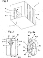
- Fig. 1 shows an elevator car 1 consisting of a floor frame with bottom 3, walls 4 forming wall panels 5, a ceiling 6 and a cabin entrance 7. Not shown are the entrance doors and the bottom frame 2 supporting support frame.
- Fig. 2 shows a first wall panel 5.1 and a second wall panel 5.2 of the elevator car 1.
- the first wall panel 5.1 has a first fold 5.11, which forms a first end face 5.12.
- the second wall panel 5.2 has a second turn 5.21, which forms a second end face 5.22.
- the wall panels 5.1, 5.2 are connected at their narrow side SCH with the bottom frame 2 and along the panel height H at least once at the end faces 5.12, 5.22 with each other.
- a section marked A is in the FIGS. 3 to 5 explained in more detail.
- Fig. 3 shows a horizontal section along the line BB of Fig. 2 ,
- the first fold 5.11 of the first wall panel 5.1 forms the first end face 5.12 of the first wall panel 5.1.
- the second turn 5.21 of the second wall panel 5.2 forms the second end face 5.22 of the second wall panel 5.2.
- the first wall panel 5.1 is connected by means of a connecting element 8 with the second wall panel 5.2, wherein the first fold 5.11 and the second fold 5.21 lie on each other.
- the end panels interconnected wall panels 51, 5.2 form on a passenger side 9 of the elevator car 1, a flat surface, wherein the two Umbüge 5.11, 5.21 and the connecting element 8 are arranged on an outer side 10 of the elevator car 1.
- FIG. 3 shown example of a connecting element 8 is formed in one piece and is made for example of plastic by means of an injection molding process. Details of the one-piece connecting element 8 are in Fig. 5 shown. The principal mode of action of the connecting element 8 is in Fig. 4 and FIG. 6 to FIG. 9 explained with reference to a multi-piece connecting element 8.
- Fig. 4 shows the section A of Fig. 2 in which the multi-piece connecting element 8 connecting the wall panels 5.1, 5.2 is cut in the vertical direction, wherein the connecting element 8 consists of a connecting body, a spring element and a screw.
- the connecting element 8 consists of a foot 8.1 and a top 8.2. Foot 8.1 and upper part 8.2 form a one-piece Verbindurigspian, the foot 8.1 has a directed against the upper part stamp 8.11.
- a first spring element 8.3 and a second spring element 8.4 form a one-piece spring body 8.5, which is pressed centrally by means of the punch 8:11 and by means of a screw 8.6 against the upper part 8.2.
- the spring body 8.5 is made for example of a spring steel sheet.
- the first spring element 8.3 is supported on the upper part 8.2 and on one side of the first turn 5.11.
- the foot 8.1 serves as an abutment and is supported on the other side of the 5.11.
- the second spring element 8.4 is supported at the top 8.2 and on the one side of the second umb 5.21. The other side of the second turn 5.21 presses on one side of the first turn 5.11.
- Fig. 5 and Fig. 5a show a variant of an integral connecting element 8 for connecting the first wall panel 5.1 with the second wall panel 5.2.
- the connecting element 8 of Fig. 4 is the connecting element 8 of Fig. 5 . 5a made of a single casting and is made for example of plastic by means of an injection molding process.
- the one-piece connecting element 8 has a low weight and is inexpensive to produce as a mass product.
- the first spring element 8.3 and the second spring element 8.4 form the spring body 8.5, which is part of the upper part 8.2 and performs the same function as the spring body 8.5 of Fig. 4 ,
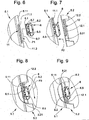
- the Fig. 6 to 9 show the assembly of the multi-piece connecting element 8 for connecting the first wall panel 5.1 with the second wall panel 5.2.
- the assembly of the one-piece connecting element 8 is substantially identical to the assembly of the multi-piece connecting element eighth
- Fig. 6 shows the first wall panel 5.1 with a first slot 11 on the first turn 5.11.
- the first slot 11 has a wide area 11.1 and a narrow or a tapered area 11.2.
- the narrow slot 11.2 is directed downwards.
- the foot 8.1 of the connecting element 8 is less wide than the wide portion 11.1 of the first slot 11 and wider than the narrow portion 11.2 of the first slot 11.
- a first arrow P1 symbolizes the movement for tool-free mounting of the connecting element 8 on the first turn 5.11 of the first wall panel 5.1.
- the connecting element 8 is handled purely manually during assembly, wherein the upper part 8.2 of the connecting element 8 serves as a mounting handle, which is held for example by means of the thumb and forefinger.
- the foot 8.1 of the connecting element 8 is introduced to a tapered portion 8.7 of the upper part 8.2 with a horizontal movement in the wide area 11.1 of the slot. Thereafter, the connecting element 8 is introduced at the tapered portion 8.7 of the upper part 8.2 with a vertical downward movement in the narrow portion 11.2 of the first slot 11, the foot 8.1 slides on a back 5.13 of the first 5.11 and the first spring element 8.3 on a front side 5.14 of the first turn 5.11 presses on both sides of the first slot 11. The insertion of the connecting element 8 is continued until the tapered portion 8.7 of the upper part 8.2 is present at a first stop 8.12 at the end of the narrow portion 11.2 of the first slot 11 on the first turn 5.11.
- Fig. 7 shows how the second turn 5.21 of the second wall panel 5.2 is slipped over the connecting element 8.
- a second slot 12 is provided with a wide area 12.1 and a narrow or a tapered area 12.2, the narrow area 12.2 of the second slot 12 being directed upwards.
- a second arrow P2 symbolizes the movement for putting the second turn 5.12 over the connecting element 8.
- Fig. 8 shows the folded over the connecting element 8 second turn 5.21.
- the first flap 5.11 and the second flap 5.21 are now close together.
- a third arrow P3 symbolizes the movement for connecting the second turn 5.21 with the connecting element 8.
- the narrow portion 12.2 of the second slot 12 slides over the tapered portion 8.7 of the upper part 8.2 to the upper end of the narrow portion 12.2 of second slot 12 at a second stop 8.13 of the tapered portion 8.7 of the connecting element 8 is present.
- the narrow portion extends 12.2 of the second slot 12 to before the first spring element 8.3 as in the FIGS. 4 and 5 shown.
- the second spring element 8.4 is supported on the upper part 8.2 and on the one side of the second Umbugs 5.21.
- the other side of the second turn 5.21 presses on one side of the first turn 5.11.
- Fig. 9 shows the ready made connection between the first turn 5.11 and the second turn 5.21.
- the connecting element 8 is neither visible nor accessible from the passenger side 9. For cabin passengers, there is no risk of injury from the connection element. With the hidden arrangement of the connecting element 8 is no reason for vandalism.
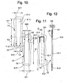
- Fig. 10 shows how the first slot 11 and the second slot 12 in the finished compound according to Fig. 9 superimposed.
- the slots 11, 12 are shown pushed apart along the lines L1, L2.
- Fig. 10 a first bearing surface A1 or a first contact zone of the first spring element 8.3 on the first turn 5.11 and a second bearing surface A2 or a second contact zone of the second spring element 8.4 on the second bend 5.21.
- the first spring element 8.3 extends through the wide region 12.1 of the second slot 12 and presses on the first contact surface A1 on the first turn 5.11.
- the second spring element 8.4 presses on the second support surface A2 on the second turn 5.21.
- the first slot 11 and the second slot 12 are dimensioned.
- the mass can change depending on the load and the sheet thickness of the wall panels 5.1, 5.2.
- the upper part 8.2 of the connecting element 8 is a few tenths of a mm narrower than b11 or b21.
- the tapered area 8.7 of Link element 8 is a few tenths of a millimeter narrower than b12 and b22, respectively.
- the tapered region 8.7 extends from the first stop 8.12 to the second stop 8.13 and corresponds to about 112.
- the spring body 8.5 is designed for a certain material thickness of the wall panels 5.1, 5.2.
- a certain spring body 8.5 fits wall panels 5.1, 5.2 with a specific sheet thickness, for example 1.25 mm. Too small a sheet thickness or too large a sheet thickness claimed the spring elements 8.3, 8.4 too little or too much.
- FIGS. 11 and 12 show how a wall panel with a too large wall thickness is connectable.
- the second wall panel 5.2 has a wall thickness that is too large by the thickness D1.
- the second loop 5.21 is made thinner about the narrow area 12.2 of the second slot 12 by the thickness D1, for example by embossing, forging or milling, and then has a thickness of D2.
- the edited fold area is labeled UB.
- Fig. 12 shows the thicknesses D1, D2 and is a section along the line CC of Fig. 11 ,
- connection for wall panels can also be used for ceiling panels or floor panels of the elevator car.
Landscapes
- Engineering & Computer Science (AREA)
- Civil Engineering (AREA)
- Mechanical Engineering (AREA)
- Structural Engineering (AREA)
- Cage And Drive Apparatuses For Elevators (AREA)
- Finishing Walls (AREA)
- Connection Of Plates (AREA)
Claims (8)
- Dispositif pour relier des panneaux (5.1, 5.2) d'une cabine d'ascenseur (1), étant précisé que les panneaux (5.1, 5.2) sont aptes à être reliés entre eux, côté frontal, à l'aide d'au moins un élément de liaison (8),
caractérisé en ce qu'il est prévu sur un premier panneau (5.1) au moins une première fente (11), et sur un deuxième panneau (5.2) au moins une deuxième fente (12), et l'élément de liaison (8) est apte à être introduit sans outil dans la première fente (11), et le deuxième panneau (5.2) est apte à être enfilé sur l'élément de liaison (8) au niveau de la deuxième fente (12), étant précisé qu'un premier élément à ressort (8.3) d'un corps à ressort (8.5) de l'élément de liaison (8) appuie sur le premier panneau (5.1) tandis qu'un deuxième élément à ressort (8.4) du corps à ressort (8.5) de l'élément de liaison (8) appuie sur le deuxième panneau (5.2). - Dispositif selon la revendication 1, caractérisé en ce que le premier panneau (5.1) comporte, côté frontal, une première partie repliée (5.11) sur laquelle est disposée la première fente (11) avec une zone large (11.1) et une zone étroite (11.2), et le deuxième panneau (5.2) comporte, côté frontal, une deuxième partie repliée (5.21) sur laquelle est disposée la deuxième fente (12) avec une zone large (12.1) et une zone étroite (12.2).
- Dispositif selon la revendication 2, caractérisé en ce que la zone large (11.1, 12.1) est plus large que l'élément de liaison (8) et en ce que l'élément de liaison (8) comporte une zone effilée (8.7) au niveau de laquelle il est apte à être glissé dans la zone étroite (11.2, 12.2) de la fente (11, 12).
- Dispositif selon l'une des revendications 2 à 3, caractérisé en ce que le premier élément à ressort (8.3) du corps à ressort (8.5) est plus large que la zone étroite (11.2) de la première fente (11), et le deuxième élément à ressort (8.4) est plus étroit que la zone étroite (12.2) de la deuxième fente (12).
- Dispositif selon l'une des revendications précédentes, caractérisé en ce que l'élément de liaison (8) comporte une partie supérieure (8.2) qui sert de poignée de montage pour glisser l'élément de liaison (8) dans la première fente (11).
- Dispositif selon la revendication 2, caractérisé en ce que la deuxième partie repliée (5.21) présente, au voisinage (UB) de la zone étroite (12.2) de la deuxième fente (12), une épaisseur réduite (D2).
- Procédé avec les étapes suivantes pour relier des panneaux (5) d'une cabine d'ascenseur (1), étant précisé qu'un premier panneau (5.1) présente au moins une première fente (11), et un deuxième panneau (5.2) au moins une deuxième fente (12) :a) introduction d'un élément de liaison (8) dans la première fente (11), étant précisé qu'un premier élément à ressort (8.3) de l'élément de liaison (8) appuie sur une première partie repliée (5.11) du premier panneau (5.1), etb) enfilement d'une deuxième partie repliée (5.21) du deuxième panneau (5.2), au niveau de la deuxième fente (12), sur l'élément de liaison (8), étant précisé qu'un deuxième élément à ressort (8.4) de l'élément de liaison (8) appuie sur la deuxième partie repliée (5.21).
- Procédé selon la revendication 7, étant précisé que l'élément de liaison (8) est glissé, au niveau d'une zone effilée (8.7), dans une zone étroite (11.1) de la première fente (11), et que la deuxième partie repliée (5.21) est glissée, au niveau d'une zone étroite (12.1) de la deuxième fente (12), dans la zone effilée (8.7) de l'élément de liaison (8).
Priority Applications (1)
| Application Number | Priority Date | Filing Date | Title |
|---|---|---|---|
| EP12701127.8A EP2673231B1 (fr) | 2011-02-11 | 2012-01-26 | Dispositif de raccordement de panneaux d'une cabine d'ascenseur |
Applications Claiming Priority (3)
| Application Number | Priority Date | Filing Date | Title |
|---|---|---|---|
| EP11154176 | 2011-02-11 | ||
| EP12701127.8A EP2673231B1 (fr) | 2011-02-11 | 2012-01-26 | Dispositif de raccordement de panneaux d'une cabine d'ascenseur |
| PCT/EP2012/051194 WO2012107294A1 (fr) | 2011-02-11 | 2012-01-26 | Dispositif de raccordement de panneaux d'une cabine d'ascenseur |
Publications (2)
| Publication Number | Publication Date |
|---|---|
| EP2673231A1 EP2673231A1 (fr) | 2013-12-18 |
| EP2673231B1 true EP2673231B1 (fr) | 2015-08-12 |
Family
ID=44169013
Family Applications (1)
| Application Number | Title | Priority Date | Filing Date |
|---|---|---|---|
| EP12701127.8A Active EP2673231B1 (fr) | 2011-02-11 | 2012-01-26 | Dispositif de raccordement de panneaux d'une cabine d'ascenseur |
Country Status (12)
| Country | Link |
|---|---|
| US (1) | US9340394B2 (fr) |
| EP (1) | EP2673231B1 (fr) |
| KR (1) | KR101914807B1 (fr) |
| CN (1) | CN103402903B (fr) |
| AU (1) | AU2012215622B2 (fr) |
| BR (1) | BR112013020263B1 (fr) |
| CA (1) | CA2824513C (fr) |
| ES (1) | ES2552911T3 (fr) |
| MX (1) | MX2013009286A (fr) |
| MY (1) | MY161307A (fr) |
| SG (1) | SG191943A1 (fr) |
| WO (1) | WO2012107294A1 (fr) |
Families Citing this family (4)
| Publication number | Priority date | Publication date | Assignee | Title |
|---|---|---|---|---|
| EP2796399B1 (fr) * | 2013-04-22 | 2015-10-28 | KONE Corporation | Ensemble plate-forme et procédé de fabrication d'une cabine d'ascenseur |
| US20150175388A1 (en) * | 2013-12-20 | 2015-06-25 | Thyssenkrupp Elevator Corporation | System and Method For Assembling An Elevator Cab |
| JP7518487B1 (ja) | 2023-04-05 | 2024-07-18 | フジテック株式会社 | エレベータかご、エレベータ及び接続具 |
| JP7449500B1 (ja) | 2023-04-10 | 2024-03-14 | フジテック株式会社 | エレベータかご、エレベータ及び接続具 |
Family Cites Families (18)
| Publication number | Priority date | Publication date | Assignee | Title |
|---|---|---|---|---|
| US2490663A (en) * | 1945-07-23 | 1949-12-06 | Cuyahoga Spring Company | Wall panel securing means |
| US2915151A (en) * | 1957-12-04 | 1959-12-01 | Gen Steel Products Corp | Partition structures |
| DE2453196C3 (de) * | 1974-11-09 | 1979-08-09 | Thyssen Aufzuege Gmbh, 7303 Neuhausen | Vorrichtung und Verfahren zum Verbinden von Fahrkorb-Wandlamellen |
| US4199907A (en) * | 1978-08-23 | 1980-04-29 | Westinghouse Electric Corp. | Panel joint |
| US4251969A (en) * | 1979-10-02 | 1981-02-24 | Westinghouse Electric Corp. | Panel joint |
| US4430838A (en) * | 1980-08-07 | 1984-02-14 | Westinghouse Electric Corp. | Panel joints |
| FR2721074B1 (fr) * | 1994-06-09 | 1996-07-26 | Otis Elevator Co | Verrou pour l'assemblage de panneaux latéraux, d'une plate-forme et d'un plafond de cabine d'ascenseur et procédé d'assemblage. |
| US5556079A (en) * | 1995-05-01 | 1996-09-17 | West; Ronald R. | Fencing system with mounting clips |
| DE19848746C2 (de) * | 1998-10-22 | 2002-12-19 | Thyssen Aufzugswerke Gmbh | System zur Verbindung von Wandlamellen einer Aufzugskabine |
| US6802168B1 (en) * | 2002-12-03 | 2004-10-12 | Larry A. Minnick | Modular wall panel system with cooperatively tapered connector pins and slots |
| ITBO20040704A1 (it) * | 2004-11-15 | 2005-02-15 | Carlo Michiara | Cabina a montaggio agevolato, particolarmente per ascensori e soimili |
| SG133494A1 (en) * | 2005-12-20 | 2007-07-30 | Inventio Ag | Elevator cab and construction method thereof |
| JP2008120470A (ja) * | 2006-11-08 | 2008-05-29 | Mitsubishi Electric Corp | エレベータのかご室 |
| US20080127577A1 (en) * | 2006-12-04 | 2008-06-05 | Pius Elmiger | Connecting device and method for connecting two wall elements of an elevator cage |
| JP2008280118A (ja) * | 2007-05-09 | 2008-11-20 | Mitsubishi Electric Corp | エレベータのかご室 |
| CN201080941Y (zh) * | 2007-09-11 | 2008-07-02 | 沈阳博林特电梯有限公司 | 轿厢壁板的快速连接结构 |
| JP2009263096A (ja) * | 2008-04-25 | 2009-11-12 | Mitsubishi Electric Corp | エレベータのかご室壁 |
| JP2013249178A (ja) * | 2012-06-01 | 2013-12-12 | Mitsubishi Electric Corp | エレベータのかご室 |
-
2012
- 2012-01-26 MY MYPI2013002523A patent/MY161307A/en unknown
- 2012-01-26 CN CN201280008360.5A patent/CN103402903B/zh active Active
- 2012-01-26 WO PCT/EP2012/051194 patent/WO2012107294A1/fr not_active Ceased
- 2012-01-26 SG SG2013053384A patent/SG191943A1/en unknown
- 2012-01-26 AU AU2012215622A patent/AU2012215622B2/en active Active
- 2012-01-26 ES ES12701127.8T patent/ES2552911T3/es active Active
- 2012-01-26 CA CA2824513A patent/CA2824513C/fr active Active
- 2012-01-26 BR BR112013020263-7A patent/BR112013020263B1/pt active IP Right Grant
- 2012-01-26 KR KR1020137023786A patent/KR101914807B1/ko active Active
- 2012-01-26 MX MX2013009286A patent/MX2013009286A/es active IP Right Grant
- 2012-01-26 EP EP12701127.8A patent/EP2673231B1/fr active Active
- 2012-02-09 US US13/369,391 patent/US9340394B2/en active Active
Also Published As
| Publication number | Publication date |
|---|---|
| AU2012215622A1 (en) | 2013-07-18 |
| US20120205199A1 (en) | 2012-08-16 |
| EP2673231A1 (fr) | 2013-12-18 |
| WO2012107294A1 (fr) | 2012-08-16 |
| MX2013009286A (es) | 2013-09-06 |
| ES2552911T3 (es) | 2015-12-03 |
| AU2012215622B2 (en) | 2017-05-18 |
| MY161307A (en) | 2017-04-14 |
| KR20140035343A (ko) | 2014-03-21 |
| NZ612564A (en) | 2015-01-30 |
| CA2824513C (fr) | 2019-03-12 |
| HK1189562A1 (zh) | 2014-06-13 |
| CN103402903A (zh) | 2013-11-20 |
| BR112013020263B1 (pt) | 2021-02-09 |
| CN103402903B (zh) | 2016-01-27 |
| BR112013020263A2 (pt) | 2016-10-18 |
| KR101914807B1 (ko) | 2018-12-28 |
| US9340394B2 (en) | 2016-05-17 |
| CA2824513A1 (fr) | 2012-08-16 |
| SG191943A1 (en) | 2013-08-30 |
Similar Documents
| Publication | Publication Date | Title |
|---|---|---|
| DE102020005127A1 (de) | Sitzbezug-befestigungsklemme | |
| DE3247555A1 (de) | Selbstlochende mutter | |
| DE202008018315U1 (de) | Fahrzeugsitzgleitvorrichtung | |
| DE4402864C2 (de) | Rückenlehnenpolster für Rücksitze von Kraftfahrzeugen | |
| DE102017113450B4 (de) | Am Sitz angebrachte einstellbare Gurtführung für einen Sitzgurt | |
| DE69002037T2 (de) | Rollvorrichtung für Schiebetüren, -fenster oder ähnliches. | |
| DE102011050206A1 (de) | Gleitschiene für einen Fahrzeugsitz und mit einer solchen Gleitschiene ausgestatteter Fahrzeugsitz | |
| DE102018009607B4 (de) | Gummianschlag | |
| DE102011086373A1 (de) | Steckzunge | |
| DE102013010577A1 (de) | "Korpusschiene für eine Führungseinrichtung, Führungsvorrichtung, Möbel sowie Verfahren zur Herstellung einer Korpusschiene" | |
| DE102022109073A1 (de) | Befestigungselement | |
| DE102017208726B4 (de) | Sitzlängsverstellvorrichtung | |
| DE4424632C2 (de) | Einstellbarer Anschlag, System von Anschlägen und Verfahren zur Bildung eines Systems von Anschlägen | |
| WO2012107294A1 (fr) | Dispositif de raccordement de panneaux d'une cabine d'ascenseur | |
| DE3012754C2 (de) | Vorrichtung zum Verbinden des Schultergurtbandes eines Sicherheitsgurtes mit einem Träger, insbesondere einem Tür- oder Fensterholm eines Kraftfahrzeuges | |
| EP2106984B1 (fr) | Revêtement à plis | |
| EP3735150B1 (fr) | Ensemble formé d'une nervure d'appui pour fond de tiroir et d'un dispositif de retenue | |
| EP3840981A1 (fr) | Système pour relier un profilé de fixation d'un dispositif de siège d'un véhicule à un élément support d'un sol de véhicule | |
| EP3973818A1 (fr) | Paroi latérale de tiroir | |
| EP3850986B1 (fr) | Tiroir d'armoire pour un élément d'armoire | |
| WO2022223700A1 (fr) | Procédé pour produire un composant de chemin de câbles, presse à moulure pour produire un tel composant de chemin de câbles et composant de chemin de câbles produit avec celui-ci | |
| DE2741875C2 (de) | Bürstenhalter mit Rollbandfeder | |
| DE3326479C2 (de) | Brieflocher | |
| EP2592967B1 (fr) | Systeme d'ouverture et/ou fermeture et processus de montage | |
| DE102007024711B4 (de) | Vorrichtung und Verfahren zum Clinchen von Bauteilen |
Legal Events
| Date | Code | Title | Description |
|---|---|---|---|
| PUAI | Public reference made under article 153(3) epc to a published international application that has entered the european phase |
Free format text: ORIGINAL CODE: 0009012 |
|
| 17P | Request for examination filed |
Effective date: 20130628 |
|
| AK | Designated contracting states |
Kind code of ref document: A1 Designated state(s): AL AT BE BG CH CY CZ DE DK EE ES FI FR GB GR HR HU IE IS IT LI LT LU LV MC MK MT NL NO PL PT RO RS SE SI SK SM TR |
|
| DAX | Request for extension of the european patent (deleted) | ||
| GRAP | Despatch of communication of intention to grant a patent |
Free format text: ORIGINAL CODE: EPIDOSNIGR1 |
|
| INTG | Intention to grant announced |
Effective date: 20141028 |
|
| GRAP | Despatch of communication of intention to grant a patent |
Free format text: ORIGINAL CODE: EPIDOSNIGR1 |
|
| INTG | Intention to grant announced |
Effective date: 20150306 |
|
| GRAS | Grant fee paid |
Free format text: ORIGINAL CODE: EPIDOSNIGR3 |
|
| GRAA | (expected) grant |
Free format text: ORIGINAL CODE: 0009210 |
|
| AK | Designated contracting states |
Kind code of ref document: B1 Designated state(s): AL AT BE BG CH CY CZ DE DK EE ES FI FR GB GR HR HU IE IS IT LI LT LU LV MC MK MT NL NO PL PT RO RS SE SI SK SM TR |
|
| REG | Reference to a national code |
Ref country code: GB Ref legal event code: FG4D Free format text: NOT ENGLISH |
|
| REG | Reference to a national code |
Ref country code: CH Ref legal event code: EP |
|
| REG | Reference to a national code |
Ref country code: AT Ref legal event code: REF Ref document number: 741955 Country of ref document: AT Kind code of ref document: T Effective date: 20150815 |
|
| REG | Reference to a national code |
Ref country code: IE Ref legal event code: FG4D Free format text: LANGUAGE OF EP DOCUMENT: GERMAN |
|
| REG | Reference to a national code |
Ref country code: DE Ref legal event code: R096 Ref document number: 502012004101 Country of ref document: DE |
|
| REG | Reference to a national code |
Ref country code: ES Ref legal event code: FG2A Ref document number: 2552911 Country of ref document: ES Kind code of ref document: T3 Effective date: 20151203 |
|
| REG | Reference to a national code |
Ref country code: LT Ref legal event code: MG4D |
|
| REG | Reference to a national code |
Ref country code: NL Ref legal event code: MP Effective date: 20150812 |
|
| REG | Reference to a national code |
Ref country code: FR Ref legal event code: PLFP Year of fee payment: 5 |
|
| PG25 | Lapsed in a contracting state [announced via postgrant information from national office to epo] |
Ref country code: LV Free format text: LAPSE BECAUSE OF FAILURE TO SUBMIT A TRANSLATION OF THE DESCRIPTION OR TO PAY THE FEE WITHIN THE PRESCRIBED TIME-LIMIT Effective date: 20150812 Ref country code: GR Free format text: LAPSE BECAUSE OF FAILURE TO SUBMIT A TRANSLATION OF THE DESCRIPTION OR TO PAY THE FEE WITHIN THE PRESCRIBED TIME-LIMIT Effective date: 20151113 Ref country code: NO Free format text: LAPSE BECAUSE OF FAILURE TO SUBMIT A TRANSLATION OF THE DESCRIPTION OR TO PAY THE FEE WITHIN THE PRESCRIBED TIME-LIMIT Effective date: 20151112 Ref country code: FI Free format text: LAPSE BECAUSE OF FAILURE TO SUBMIT A TRANSLATION OF THE DESCRIPTION OR TO PAY THE FEE WITHIN THE PRESCRIBED TIME-LIMIT Effective date: 20150812 Ref country code: LT Free format text: LAPSE BECAUSE OF FAILURE TO SUBMIT A TRANSLATION OF THE DESCRIPTION OR TO PAY THE FEE WITHIN THE PRESCRIBED TIME-LIMIT Effective date: 20150812 |
|
| PG25 | Lapsed in a contracting state [announced via postgrant information from national office to epo] |
Ref country code: IS Free format text: LAPSE BECAUSE OF FAILURE TO SUBMIT A TRANSLATION OF THE DESCRIPTION OR TO PAY THE FEE WITHIN THE PRESCRIBED TIME-LIMIT Effective date: 20151212 Ref country code: PT Free format text: LAPSE BECAUSE OF FAILURE TO SUBMIT A TRANSLATION OF THE DESCRIPTION OR TO PAY THE FEE WITHIN THE PRESCRIBED TIME-LIMIT Effective date: 20151214 Ref country code: PL Free format text: LAPSE BECAUSE OF FAILURE TO SUBMIT A TRANSLATION OF THE DESCRIPTION OR TO PAY THE FEE WITHIN THE PRESCRIBED TIME-LIMIT Effective date: 20150812 Ref country code: HR Free format text: LAPSE BECAUSE OF FAILURE TO SUBMIT A TRANSLATION OF THE DESCRIPTION OR TO PAY THE FEE WITHIN THE PRESCRIBED TIME-LIMIT Effective date: 20150812 Ref country code: RS Free format text: LAPSE BECAUSE OF FAILURE TO SUBMIT A TRANSLATION OF THE DESCRIPTION OR TO PAY THE FEE WITHIN THE PRESCRIBED TIME-LIMIT Effective date: 20150812 Ref country code: SE Free format text: LAPSE BECAUSE OF FAILURE TO SUBMIT A TRANSLATION OF THE DESCRIPTION OR TO PAY THE FEE WITHIN THE PRESCRIBED TIME-LIMIT Effective date: 20150812 |
|
| PG25 | Lapsed in a contracting state [announced via postgrant information from national office to epo] |
Ref country code: NL Free format text: LAPSE BECAUSE OF FAILURE TO SUBMIT A TRANSLATION OF THE DESCRIPTION OR TO PAY THE FEE WITHIN THE PRESCRIBED TIME-LIMIT Effective date: 20150812 |
|
| PG25 | Lapsed in a contracting state [announced via postgrant information from national office to epo] |
Ref country code: SK Free format text: LAPSE BECAUSE OF FAILURE TO SUBMIT A TRANSLATION OF THE DESCRIPTION OR TO PAY THE FEE WITHIN THE PRESCRIBED TIME-LIMIT Effective date: 20150812 Ref country code: DK Free format text: LAPSE BECAUSE OF FAILURE TO SUBMIT A TRANSLATION OF THE DESCRIPTION OR TO PAY THE FEE WITHIN THE PRESCRIBED TIME-LIMIT Effective date: 20150812 Ref country code: EE Free format text: LAPSE BECAUSE OF FAILURE TO SUBMIT A TRANSLATION OF THE DESCRIPTION OR TO PAY THE FEE WITHIN THE PRESCRIBED TIME-LIMIT Effective date: 20150812 |
|
| REG | Reference to a national code |
Ref country code: DE Ref legal event code: R097 Ref document number: 502012004101 Country of ref document: DE |
|
| PG25 | Lapsed in a contracting state [announced via postgrant information from national office to epo] |
Ref country code: BE Free format text: LAPSE BECAUSE OF NON-PAYMENT OF DUE FEES Effective date: 20160131 Ref country code: RO Free format text: LAPSE BECAUSE OF FAILURE TO SUBMIT A TRANSLATION OF THE DESCRIPTION OR TO PAY THE FEE WITHIN THE PRESCRIBED TIME-LIMIT Effective date: 20150812 |
|
| PLBE | No opposition filed within time limit |
Free format text: ORIGINAL CODE: 0009261 |
|
| STAA | Information on the status of an ep patent application or granted ep patent |
Free format text: STATUS: NO OPPOSITION FILED WITHIN TIME LIMIT |
|
| 26N | No opposition filed |
Effective date: 20160513 |
|
| PG25 | Lapsed in a contracting state [announced via postgrant information from national office to epo] |
Ref country code: SI Free format text: LAPSE BECAUSE OF FAILURE TO SUBMIT A TRANSLATION OF THE DESCRIPTION OR TO PAY THE FEE WITHIN THE PRESCRIBED TIME-LIMIT Effective date: 20150812 Ref country code: LU Free format text: LAPSE BECAUSE OF FAILURE TO SUBMIT A TRANSLATION OF THE DESCRIPTION OR TO PAY THE FEE WITHIN THE PRESCRIBED TIME-LIMIT Effective date: 20160126 |
|
| PG25 | Lapsed in a contracting state [announced via postgrant information from national office to epo] |
Ref country code: MC Free format text: LAPSE BECAUSE OF FAILURE TO SUBMIT A TRANSLATION OF THE DESCRIPTION OR TO PAY THE FEE WITHIN THE PRESCRIBED TIME-LIMIT Effective date: 20150812 |
|
| REG | Reference to a national code |
Ref country code: IE Ref legal event code: MM4A |
|
| REG | Reference to a national code |
Ref country code: FR Ref legal event code: PLFP Year of fee payment: 6 |
|
| PG25 | Lapsed in a contracting state [announced via postgrant information from national office to epo] |
Ref country code: IE Free format text: LAPSE BECAUSE OF NON-PAYMENT OF DUE FEES Effective date: 20160126 |
|
| PG25 | Lapsed in a contracting state [announced via postgrant information from national office to epo] |
Ref country code: MT Free format text: LAPSE BECAUSE OF FAILURE TO SUBMIT A TRANSLATION OF THE DESCRIPTION OR TO PAY THE FEE WITHIN THE PRESCRIBED TIME-LIMIT Effective date: 20150812 |
|
| REG | Reference to a national code |
Ref country code: FR Ref legal event code: PLFP Year of fee payment: 7 |
|
| REG | Reference to a national code |
Ref country code: AT Ref legal event code: MM01 Ref document number: 741955 Country of ref document: AT Kind code of ref document: T Effective date: 20170126 |
|
| PG25 | Lapsed in a contracting state [announced via postgrant information from national office to epo] |
Ref country code: CY Free format text: LAPSE BECAUSE OF FAILURE TO SUBMIT A TRANSLATION OF THE DESCRIPTION OR TO PAY THE FEE WITHIN THE PRESCRIBED TIME-LIMIT Effective date: 20150812 Ref country code: HU Free format text: LAPSE BECAUSE OF FAILURE TO SUBMIT A TRANSLATION OF THE DESCRIPTION OR TO PAY THE FEE WITHIN THE PRESCRIBED TIME-LIMIT; INVALID AB INITIO Effective date: 20120126 Ref country code: AT Free format text: LAPSE BECAUSE OF NON-PAYMENT OF DUE FEES Effective date: 20170126 Ref country code: SM Free format text: LAPSE BECAUSE OF FAILURE TO SUBMIT A TRANSLATION OF THE DESCRIPTION OR TO PAY THE FEE WITHIN THE PRESCRIBED TIME-LIMIT Effective date: 20150812 |
|
| PG25 | Lapsed in a contracting state [announced via postgrant information from national office to epo] |
Ref country code: MK Free format text: LAPSE BECAUSE OF FAILURE TO SUBMIT A TRANSLATION OF THE DESCRIPTION OR TO PAY THE FEE WITHIN THE PRESCRIBED TIME-LIMIT Effective date: 20150812 Ref country code: TR Free format text: LAPSE BECAUSE OF FAILURE TO SUBMIT A TRANSLATION OF THE DESCRIPTION OR TO PAY THE FEE WITHIN THE PRESCRIBED TIME-LIMIT Effective date: 20150812 |
|
| PG25 | Lapsed in a contracting state [announced via postgrant information from national office to epo] |
Ref country code: BG Free format text: LAPSE BECAUSE OF FAILURE TO SUBMIT A TRANSLATION OF THE DESCRIPTION OR TO PAY THE FEE WITHIN THE PRESCRIBED TIME-LIMIT Effective date: 20150812 |
|
| PG25 | Lapsed in a contracting state [announced via postgrant information from national office to epo] |
Ref country code: AL Free format text: LAPSE BECAUSE OF FAILURE TO SUBMIT A TRANSLATION OF THE DESCRIPTION OR TO PAY THE FEE WITHIN THE PRESCRIBED TIME-LIMIT Effective date: 20150812 |
|
| PGFP | Annual fee paid to national office [announced via postgrant information from national office to epo] |
Ref country code: CZ Payment date: 20230125 Year of fee payment: 12 |
|
| PG25 | Lapsed in a contracting state [announced via postgrant information from national office to epo] |
Ref country code: CZ Free format text: LAPSE BECAUSE OF NON-PAYMENT OF DUE FEES Effective date: 20240126 |
|
| PG25 | Lapsed in a contracting state [announced via postgrant information from national office to epo] |
Ref country code: CZ Free format text: LAPSE BECAUSE OF NON-PAYMENT OF DUE FEES Effective date: 20240126 |
|
| REG | Reference to a national code |
Ref country code: DE Ref legal event code: R084 Ref document number: 502012004101 Country of ref document: DE |
|
| REG | Reference to a national code |
Ref country code: CH Ref legal event code: U11 Free format text: ST27 STATUS EVENT CODE: U-0-0-U10-U11 (AS PROVIDED BY THE NATIONAL OFFICE) Effective date: 20260201 |
|
| PGFP | Annual fee paid to national office [announced via postgrant information from national office to epo] |
Ref country code: GB Payment date: 20260126 Year of fee payment: 15 |
|
| PGFP | Annual fee paid to national office [announced via postgrant information from national office to epo] |
Ref country code: ES Payment date: 20260210 Year of fee payment: 15 |
|
| PGFP | Annual fee paid to national office [announced via postgrant information from national office to epo] |
Ref country code: DE Payment date: 20260127 Year of fee payment: 15 |
|
| PGFP | Annual fee paid to national office [announced via postgrant information from national office to epo] |
Ref country code: IT Payment date: 20260123 Year of fee payment: 15 |
|
| PGFP | Annual fee paid to national office [announced via postgrant information from national office to epo] |
Ref country code: FR Payment date: 20260127 Year of fee payment: 15 |
|
| PGFP | Annual fee paid to national office [announced via postgrant information from national office to epo] |
Ref country code: CH Payment date: 20260201 Year of fee payment: 15 |