EP2673565B1 - Agencement pour la préparation d'un combustible liquide pour la combustion et procédé pour la préparation d'un combustible liquide pour la combustion - Google Patents
Agencement pour la préparation d'un combustible liquide pour la combustion et procédé pour la préparation d'un combustible liquide pour la combustion Download PDFInfo
- Publication number
- EP2673565B1 EP2673565B1 EP12701867.9A EP12701867A EP2673565B1 EP 2673565 B1 EP2673565 B1 EP 2673565B1 EP 12701867 A EP12701867 A EP 12701867A EP 2673565 B1 EP2673565 B1 EP 2673565B1
- Authority
- EP
- European Patent Office
- Prior art keywords
- liquid fuel
- reservoir
- fuel
- arrangement
- combustion
- Prior art date
- Legal status (The legal status is an assumption and is not a legal conclusion. Google has not performed a legal analysis and makes no representation as to the accuracy of the status listed.)
- Not-in-force
Links
- 239000000446 fuel Substances 0.000 title claims description 223
- 239000007788 liquid Substances 0.000 title claims description 146
- 238000002485 combustion reaction Methods 0.000 title claims description 59
- 238000000034 method Methods 0.000 title claims description 27
- 238000002360 preparation method Methods 0.000 title claims description 18
- 238000010438 heat treatment Methods 0.000 claims description 52
- 230000003134 recirculating effect Effects 0.000 claims description 19
- 238000011144 upstream manufacturing Methods 0.000 claims description 4
- 239000003350 kerosene Substances 0.000 claims description 3
- 238000009834 vaporization Methods 0.000 claims description 3
- 239000007789 gas Substances 0.000 description 60
- 238000004140 cleaning Methods 0.000 description 3
- 238000004939 coking Methods 0.000 description 3
- 238000013021 overheating Methods 0.000 description 3
- 239000000567 combustion gas Substances 0.000 description 2
- VNWKTOKETHGBQD-UHFFFAOYSA-N methane Chemical compound C VNWKTOKETHGBQD-UHFFFAOYSA-N 0.000 description 2
- 239000000203 mixture Substances 0.000 description 2
- XLYOFNOQVPJJNP-UHFFFAOYSA-N water Substances O XLYOFNOQVPJJNP-UHFFFAOYSA-N 0.000 description 2
- 230000003247 decreasing effect Effects 0.000 description 1
- 238000009792 diffusion process Methods 0.000 description 1
- 238000001704 evaporation Methods 0.000 description 1
- 230000008020 evaporation Effects 0.000 description 1
- 230000008571 general function Effects 0.000 description 1
- 239000003345 natural gas Substances 0.000 description 1
- 238000010248 power generation Methods 0.000 description 1
- 238000005086 pumping Methods 0.000 description 1
Images

Classifications
-
- F—MECHANICAL ENGINEERING; LIGHTING; HEATING; WEAPONS; BLASTING
- F02—COMBUSTION ENGINES; HOT-GAS OR COMBUSTION-PRODUCT ENGINE PLANTS
- F02C—GAS-TURBINE PLANTS; AIR INTAKES FOR JET-PROPULSION PLANTS; CONTROLLING FUEL SUPPLY IN AIR-BREATHING JET-PROPULSION PLANTS
- F02C7/00—Features, components parts, details or accessories, not provided for in, or of interest apart form groups F02C1/00 - F02C6/00; Air intakes for jet-propulsion plants
- F02C7/22—Fuel supply systems
- F02C7/224—Heating fuel before feeding to the burner
-
- F—MECHANICAL ENGINEERING; LIGHTING; HEATING; WEAPONS; BLASTING
- F23—COMBUSTION APPARATUS; COMBUSTION PROCESSES
- F23K—FEEDING FUEL TO COMBUSTION APPARATUS
- F23K5/00—Feeding or distributing other fuel to combustion apparatus
- F23K5/02—Liquid fuel
- F23K5/14—Details thereof
- F23K5/20—Preheating devices
-
- F—MECHANICAL ENGINEERING; LIGHTING; HEATING; WEAPONS; BLASTING
- F02—COMBUSTION ENGINES; HOT-GAS OR COMBUSTION-PRODUCT ENGINE PLANTS
- F02C—GAS-TURBINE PLANTS; AIR INTAKES FOR JET-PROPULSION PLANTS; CONTROLLING FUEL SUPPLY IN AIR-BREATHING JET-PROPULSION PLANTS
- F02C7/00—Features, components parts, details or accessories, not provided for in, or of interest apart form groups F02C1/00 - F02C6/00; Air intakes for jet-propulsion plants
- F02C7/26—Starting; Ignition
- F02C7/264—Ignition
-
- F—MECHANICAL ENGINEERING; LIGHTING; HEATING; WEAPONS; BLASTING
- F23—COMBUSTION APPARATUS; COMBUSTION PROCESSES
- F23K—FEEDING FUEL TO COMBUSTION APPARATUS
- F23K5/00—Feeding or distributing other fuel to combustion apparatus
- F23K5/02—Liquid fuel
- F23K5/14—Details thereof
- F23K5/22—Vaporising devices
Definitions
- the present invention relates to a preparation of liquid fuel for combustion, particularly for ignition in burners in gas turbines.
- a gas duct or gas flow path is routed through a combustion section/system located between a compressor and a turbine section.
- the combustion section may include an annular array of combustors or a single annular combustor. High pressure air from the compressor flows through the combustion section where it is mixed with fuel and burned.
- the combustors comprise (at least) one burner, and (at least) one igniter for igniting the air/fuel mixture especially during start up of the gas turbine.
- a high-pressure and a low-pressure turbine of the turbine section are mechanically connected and together drive an output power shaft.
- a low-pressure turbine (power turbine) is mechanically independent, i.e. only drives the output power shaft, and a high-pressure turbine, or so called compressor turbine, drives the compressor. This combination acts as a gas generator for the low-pressure turbine.
- the combustion gases exit the turbine section through an exhaust duct.
- DLE Dry Low Emissions
- the pressure of the liquid fuel supplied is used to break the liquid fuel in small droplets - using a mechanical device, i.e. an atomizer, - prior to the ignition. Breaking liquid fuel in droplets increases a surface area of the liquid fuel, and a small amount of fuel vapour forms around the droplets. This is ignited by the ignition spark.
- a mechanical device i.e. an atomizer
- GB 688 201 discloses a gas turbine burner according to the preamble of claim 1.
- liquid fuel could be supplied at higher pressure to increase the amount of small droplets and the surface area of the liquid fuel to ignite.
- the increased pressure would have to be e.g. supplied via separate starting nozzles that are switched off when the gas turbine is running.
- the invention provides a source of heated liquid fuel, particularly heated high pressurized liquid fuel, for example kerosene, in a reservoir.
- the reservoir is arranged in parallel with a main fuel feed of a combustion system and can be filled by said main fuel feed and/or evacuated into said main fuel feed.
- heated liquid fuel in said main fuel feed By evacuating heated liquid fuel in said main fuel feed the temperature of the liquid fuel for the burners to ignite will be increased - and the liquid fuel will be ignite more easily, i.e. the gas turbine will start more reliably.
- the reservoir contains a heating means, which heat the liquid fuel filled in the reservoir, particularly while circulating in the reservoir.
- the reservoir By arranging the reservoir in parallel with the main supply, the reservoir, i.e. the heating means could be removed for cleaning or replacement without interrupting a gas turbine operation.
- the first predetermined condition could define or correlate with (time when) the gas turbine is being prepared to start.
- the second predetermined condition could be a date when the gas turbine is started. This second condition/date could correlate - but not necessarily - with the point when the liquid fuel to be heated in the reservoir achieves a specific/suitable temperature or a heating period/duration expires.
- the heating operation can be stopped at a predetermined or suitable temperature.
- This temperature preferably measured by a thermocouple and/or controlled by a control system, should preferably be high enough to significantly increase an amount of vaporisation of a fuel when it is atomised in a burner.
- a suitable temperature could be about 50 °C up to 150 °C or more.
- the heated liquid fuel can - particularly by use of at least one valve - be directed to burners of the combustion system - via the main fuel feed - when the gas turbine is started. After successful ignition of the fuel in the burners of the combustion system, the fuel flow/feed can be switched back - particularly by use of at least one valve - to normal unheated fuel.
- the reservoir can be sized to contain enough liquid fuel for one, two or several starts of a gas turbine as required, with a signal to indicate when the temperature has reached a predetermined or desired level.
- the signal could be generated by a sensor - or based on signal generated by a sensor, particularly of a thermocouple, arranged in the reservoir - and/or could be evaluated and/or processed in a control system.
- the reservoir is sized to contain liquid fuel for two starts of the gas turbine, so that - if the gas turbine is stopped after a first start - enough (heated) liquid fuel is available in the reservoir for a second start.
- the invention provides - in a easy and efficient way - a source of heated high pressure liquid fuel, so that - when the fuel is expanded to lower pressure and broken into droplets - it vaporises more easily, allowing more reliable ignition.
- the invention provides in an easy and efficient way a recirculating circuit for heating pressurized liquid fuel in order for it to evaporate more easily when expanded to a lower pressure during start of a gas turbine.
- pressurized liquid fuel is supplied at a pressure several times e.g. 3-10 that of the compressor delivery pressure in order to provide the fine droplets required for DLE combustion.
- the supply pressure is reduced to only a few bars over the compressor delivery pressure, which in itself is then typically not significantly above atmospheric or ambient pressure.
- a flow circuit could be realized in said reservoir or with said reservoir as part of the flow circuit.
- Said reservoir could comprise a pump to pump the liquid fuel along a pipe, a duct from the reservoir towards the burners, with a return pipe to an opposite side of the reservoir - defining said flow circuit.
- the liquid fuel circulates around said flow circuit to ensure that both - fuel and pipework - reach a required temperature.
- the continuous flow of fuel around the circuit to be heated also means that the fuel is not in contact with the heating means for an extended period of time.
- said reservoir or other elements of the flow circuit comprises at least one thermocouple positioned at a probing point in said reservoir or said other elements, i.e. in said flow circuit.
- Said at least one thermocouple provides a signal to a control system, indicating that the temperature of the fuel and/or the pipework has reached a required level for liquid fuel starting.
- thermo sensor Therefore a control system could be provided to evaluate and/or to process said signal generated by said thermo sensor.
- connection of the reservoir with the (main) fuel feed can be realized by valves, particularly by two-way valves, arranged at an inlet end ("fill in end") and/or an outlet end ("evacuating end") of said reservoir or flow circuit providing different switch settings, i.e. phases of operation.
- a valve positioned in the flow circuit, particularly at the outlet end of the reservoir or flow circuit, could be switched to direct the liquid fuel (in the reservoir) either (1) back to the reservoir, in a heating phases, or (2) into the pipes to the burners, in a starting phase.
- a valve positioned in the flow circuit, particularly at the inlet end of the reservoir or flow circuit, could be switched to direct the liquid fuel of the main fuel feed either (1) (directly) into the burners, both for normal operation and in a heating phase, or (2) towards the reservoir, in a starting phase.
- the arrangement/method could operate in two phases, a heating phase and a starting phase.
- a gas turbine is preparing to start on liquid fuel - the reservoir is filled with (unheated) liquid fuel by/out of the main fuel feed.
- Valves - preferable connecting the reservoir with the main fuel feed at an inlet end and an outlet end of the reservoir or flow circuit - , particularly two-way valves, are switched so that the liquid fuel is isolated in the reservoir/in a heating circuit realized in the reservoir - or with the reservoir as part of the flow circuit.
- a (small) fuel pump could circulate the liquid fuel in the reservoir, which could dump back into an inlet end of the reservoir.
- the heating means/the heater is switched on for heating the isolated liquid fuel in the reservoir.
- a thermo sensor for example a thermocouple, indicates when the temperature of the liquid fuel to be heated in the reservoir is high enough for the gas turbine starting.
- the heating means/the heater When this temperature is reached, the heating means/the heater is turned off. If the temperature drops too low before the gas turbine is started, the heater is switched on again.
- the valves i.e. the two-way valves, are switched so that liquid fuel of the main fuel feed (main fuel flow) enters the inlet end of the reservoir (or flow circuit) and pushes (evacuates) the heated liquid fuel into the supply, i.e. back into the main fuel feed, to the burner.
- the evacuation of the reservoir could be supported by the fuel pump of the reservoir if needed.
- An advantage of the proposed arrangement by arranging the reservoir in parallel with the main fuel feed, the reservoir, i.e. the heating means, can be removed for cleaning or replacement without interrupting the gas turbine operation.
- the gas turbine is a Dry Low Emission gas turbine, that means the gas turbine is operating with a Dry Low Emission combustion. While supplying heated liquid fuel, particularly heated pressurized liquid fuel, only for starting - during operation the flame of the combustion system will provide enough temperature as well as more/higher pressure is available during operation - the rate of heating does not need to be high. Further to that - while supplying heated liquid fuel from a reservoir in which a predetermined amount of liquid fuel is heated - instead of heating a continuous flow of liquid fuel flowing upstream to the burners - the rate of heating does not need to be high.
- the rate of heating does not need to be high, the temperature of the heating means and/or the sizes of the heating means themselves do not need to be high/large which reduce the risk of coking/overheating of liquid fuel by the heating means.
- Small heaters - preferably depending on a size of the gas turbine - could be used by the invention.
- the present invention is directed to an arrangement for preparation of a liquid fuel for combustion in a gas turbine as used in for instance a power plant as schematically illustrated in Figure 1 .
- the gas turbine engine as shown in Figure 1 has an air inlet 1 at one end followed by a compressor 2 for compressing the air from said inlet.
- Combustors 3 having a can-like shell are distributed around a turbine shaft 4.
- Liquid Fuel, that means in this case heating oil, supplied by a fuel supply 13 is introduced into the respective burners 9 at 5 and is there mixed with a part of said air from the air inlet 1 for the combustion.
- the combustion chamber 8 has a burner aperture 10 through which the burner 9 is fitted.
- the burner 9 comprises a burner space where the fuel and air is mixed before being released into the combustion chamber 8 via the burner aperture 10.
- a supplying means is adapted to supply liquid fuel through an internal passage inside the burner body member for said combustion. This liquid fuel is atomized and sprayed into said burner space of the burner 9 through a pilot fuel injector nozzle.
- An ignition means (not shown) is located close to said nozzle for igniting the fuel inside the burner space for commencing combustion.
- One or more liquid fuel nozzles are located in said burner space 9 for supplying to the space atomized liquid fuel for evaporation and later combustion.
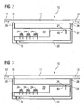
- the present invention is based on the use of a recirculating circuit 10 as shown in Figures 2 and 3 for heating pressurized liquid fuel in order for it to evaporate more easily when expanded to a lower pressure and broken into droplet's during start of the gas turbine allowing a more reliable ignition.
- the recirculation circuit 10 is arranged in parallel with the main liquid fuel feed 11 - downstream a fuel supply 12 and upstream the burners of the gas turbine supplied by a fuel supply 12 via the main fuel feed 11.
- the recirculation circuit 10 comprises a reservoir 20 with one or more heaters 24 for heating liquid fuel inside the reservoir 20, a pipe 21 from the reservoir 20 towards the burners and a return pipe 22 to the opposite side of the reservoir 20 - all together completing a flowing circuit, i.e. the recirculating circuit 10 - so that liquid fuel, pressurized liquid fuel - supplied by the main fuel feed 11 into the reservoir 20 - could circulate around this circuit 10.
- the recirculation circuit 10 further comprises a small pump 23 arranged in the return pipe 22 for pumping the liquid fuel along the pipe 21 from the reservoir 20 towards the burners and to circulate in the recirculating circuit 10.
- thermocouple 40 is arranged in the recirculating circuit 10, i.e. the thermocouple 40 is - as it can be seen in Figures 2 and 3 - located in the pipe 21.
- the thermocouple 40 is generating signals - according to a temperature of the liquid fuel in the reservoir 20, i.e. circulating in the recirculating circuit 10.
- the signals are transmitted to a control system for controlling the temperature of the liquid fuel, i.e. a temperature in the recirculating circuit 10, as well as the operational modes of the recirculating circuit 10.
- the recirculating circuit 10 is connected to the main fuel feed 11 by a first 30 and a second two-way valve 31 located at an inlet end 25 and an outlet end 26 of the recirculating circuit 10.
- the inlet end 25 - with the first valve 30 - is located upstream of the outlet end 26 - with the second valve 31 - in relation to the main fuel feed 11 so that liquid fuel flowing in the main fuel feed 11 could flow into the reservoir 20 at the inlet end 30.
- the reservoir 20 could be evacuated via the outlet end 26, i.e. the second valve 31, back to the main fuel feed 11 again.
- the reservoir 20 is sized for enough liquid fuel for two starts of a gas turbine as required.
- valves 30, 31 could be switched - in control of the control system - in different switch settings relating to different operation modes as shown in Figures 2 and 3 and as described as follows.
- Figure 2 is illustrating the recirculating circuit 10 in a heating phase.
- the gas turbine is preparing to start on liquid fuel.
- the reservoir 20 is filled with liquid fuel at a normal starting pressure.
- the heaters 24 are switched on.
- the two-way valves 30, 31 are switched so that the liquid fuel is isolated in the recirculating circuit 10.
- the small fuel pump 23 circulates the fuel, which dumps back into the inlet end 25 of the reservoir.
- the thermocouple 40 indicates when the temperature of the liquid fuel is high enough for the gas turbine starting.
- the heaters 24 are turned off. If the temperature drops too low before the gas turbine is started, the heaters 24 are switched on again.
- Figure 3 is illustrating the recirculating circuit 10 in a starting phase.
- the gas turbine is started.
- the two-way valves 30, 31 are switched so that the main fuel flow enters the inlet end 25 of the recirculating circuit 10 and the reservoir 20, and pushes the heated liquid fuel into the main fuel feed 11 - via the outlet end 26 of the recirculating circuit 10 - to the burner.
- valves 30, 31 could be switched back in the heating positions, i.e. in position of/for the heating phase ( Figure 2 ), or normal position, i.e. in position of/for the normal operating phase ( Figure 2 ), so that the fuel supply 12 fed normal unheated fuel directly to the combustion system 8.
- valve 31 could be switched to direct the liquid fuel either (1) back to the reservoir 20, in the heating phases, or (2) into the main fuel feed 11 to the burners, in a starting phase; the valve 30 could be switched to direct the liquid fuel of the main fuel feed 11 either (1) (directly) into the burners, both for normal operation and in the heating phase, or (2) towards the reservoir 20, in the starting phase.
- valves 30, 31 When the valves 30, 31 are in the starting positions, i.e. in position of/for the starting phase ( Figure 3 ), a pressure of the liquid fuel of the main fuel supply 12 then "drives" the heated liquid fuel out of the reservoir 20, i.e. the recirculating circuit 10, into the burners, that means that heated liquid fuel can be directed into the burners when the gas turbine is started.
- the heating operation will be stopped at a suitable temperature - measured by the thermocouple 40 and controlled by the control system. This temperature will be high enough to significantly increase an amount of vaporisation of a fuel when it is atomised in the burner.
- the recirculation circuit 10 is arranged in parallel with the main fuel feed 11, so that the heaters 24 can be removed for cleaning or replacement without interrupting the gas turbine operation.
- the rate of heating does not need to be high, the temperature of the heaters 24 themselves does not need to be high. Also the continuous flow of liquid fuel around the recirculation circuit 10 means that the liquid fuel is not in contact with the heaters 24 for an extended period of time. Both these factors reduce the risk of coking/overheating of liquid fuel by the heaters 24.
- the invention may be directed to a method of preparing a liquid fuel for combustion according to any preceding method claim, used for preparing liquid fuel for starting a gas turbine, particularly starting a DLE gas turbine.
- the invention may be directed to a method of preparing a liquid fuel for combustion according to any preceding method claim, wherein said heated liquid fuel is directed to a burner 9 of a combustion system 3 of a gas turbine when the gas turbine is started.
Landscapes
- Engineering & Computer Science (AREA)
- Chemical & Material Sciences (AREA)
- Combustion & Propulsion (AREA)
- Mechanical Engineering (AREA)
- General Engineering & Computer Science (AREA)
- Feeding And Controlling Fuel (AREA)
- Combustion Of Fluid Fuel (AREA)
Claims (21)
- Montage servant à préparer un combustible liquide en vue de sa combustion, notamment de son inflammation, comprenant une amenée principale (11) de combustible pour amener du combustible liquide à partir d'une alimentation (12) en combustible jusqu'à un brûleur (9), un réservoir (20) de combustible liquide et un moyen pour chauffer (24) le combustible liquide dans ledit réservoir (20), étant entendu que ledit réservoir (20) est monté en parallèle avec ladite amenée principale (11) de combustible, caractérisé en ce qu'une entrée dudit réservoir (20) est montée en amont d'une sortie dudit réservoir (20) et en ce que ledit réservoir (20) est relié à ladite amenée principale (11) de combustible par une vanne (30) en vue d'être rempli, dans un premier état prédéterminé, de combustible liquide amené par ladite amenée principale (11) de combustible et/ou en ce que ledit réservoir (20) est relié à ladite amenée principale (11) de combustible par une vanne (31) en vue de l'évacuation, dans un second état prédéterminé, de combustible liquide chauffé, chauffé dans ledit réservoir (20), dans ladite amenée principale (11) de combustible.
- Montage servant à préparer un combustible liquide en vue de sa combustion selon l'une quelconque des revendications précédentes, dans lequel ledit réservoir (20) est dimensionné pour contenir du combustible liquide en vue d'une, de deux ou de plusieurs mises en marche d'une turbine à gaz.
- Montage servant à préparer un combustible liquide en vue de sa combustion selon l'une quelconque des revendications précédentes, dans lequel ledit montage ou ledit réservoir (20) comprend un capteur (40), notamment un capteur thermique et/ou un thermocouple, produisant un signal pour indiquer quand une température dudit combustible liquide à chauffer dans ledit réservoir (20) a atteint une température prédéterminée, c'est-à-dire un niveau voulu, et/ou dans lequel ledit montage ou ledit réservoir (20) comprend une canalisation (21), une canalisation de retour (22), une conduite réalisant un circuit d'écoulement (10) dans ledit réservoir (20) ou ledit réservoir (20) faisant partie d'un circuit d'écoulement (10).
- Montage servant à préparer un combustible liquide en vue de sa combustion selon la revendication précédente, dans lequel ledit montage ou ledit réservoir (20) comprend une pompe (23) pour pomper le combustible liquide dans ladite canalisation (21) et dans ladite conduite allant dudit réservoir (20) vers un brûleur (9) et/ou pour faire circuler le combustible liquide dans ledit circuit d'écoulement (10).
- Montage servant à préparer un combustible liquide en vue de sa combustion selon l'une quelconque des revendications précédentes, dans lequel un circuit d'écoulement (10) est réalisé dans ledit réservoir (20) ou ledit réservoir (20) faisant partie du circuit d'écoulement (10).
- Montage servant à préparer un combustible liquide en vue de sa combustion selon l'une quelconque des revendications précédentes, dans lequel ledit montage, ledit réservoir (20) ou ledit circuit d'écoulement (10) comprend au moins une vanne (30, 31), notamment une vanne à deux voies, et/ou montée à une extrémité d'entrée (« extrémité de remplissage ») (25) et/ou à une extrémité de sortie (« extrémité d'évacuation ») (26) dudit réservoir (20) ou circuit d'écoulement (10).
- Montage servant à préparer un combustible liquide en vue de sa combustion selon l'une quelconque des revendications précédentes, dans lequel ledit combustible liquide est un combustible liquide sous pression et/ou ledit combustible liquide est un supercombustible liquide, notamment du kérosène ou une huile de chauffe, prévu pour une combustion à faibles émissions par voie sèche.
- Montage servant à préparer un combustible liquide en vue de sa combustion selon l'une quelconque des revendications précédentes, utilisé pour fonctionner en deux phases :- une phase de chauffage dans laquelle une turbine à gaz est préparée pour être mise en route avec du combustible liquide, et- une phase de mise en route pendant laquelle la turbine à gaz est mise en route.
- Montage servant à préparer un combustible liquide en vue de sa combustion selon la revendication précédente, utilisé pendant la phase de chauffage étant entendu que :- les vannes (30, 31), notamment montées à une extrémité d'entrée (25) et/ou à une extrémité de sortie (26) dudit réservoir (20) ou circuit d'écoulement (10), sont/est manoeuvrée(s) de telle sorte que ledit réservoir (20) est rempli de combustible liquide non chauffé par/à partir de l'amenée principale (11) de combustible et/ou le combustible liquide est isolé dans ledit réservoir (20) ;- le moyen de chauffage (24) est allumé pour chauffer le combustible liquide isolé dans ledit réservoir (20), notamment le combustible liquide circulant dans ledit réservoir (20) ;- un capteur thermique (40) indique quand une température du combustible liquide à chauffer dans ledit réservoir (20) est assez élevée pour mettre la turbine à gaz en marche, et- ledit moyen de chauffage (24) est éteint lorsque cette température est atteinte.
- Montage servant à préparer un combustible liquide en vue de sa combustion selon la revendication précédente, utilisé pendant la phase de chauffage étant entendu que :le montage est adapté de sorte que, si la température dudit combustible liquide tombe sous un seuil avant que la turbine à gaz ne soit mise en marche, ledit moyen de chauffage (24) soit rallumé.
- Montage servant à préparer un combustible liquide en vue de sa combustion selon la revendication 5, utilisé pendant la phase de chauffage étant entendu que :les vannes (30, 31), notamment montées à une extrémité d'entrée (25) et/ou à une extrémité de sortie (26) du réservoir (20) ou circuit d'écoulement (10), sont/ est manoeuvrée(s) de telle sorte que le combustible liquide amené dans ladite amenée principale (11) de combustible pénètre dans l'extrémité d'entrée (25) dudit réservoir (20) ou circuit d'écoulement (10) et repousse ledit combustible liquide chauffé hors dudit réservoir (20) dans ladite amenée principale (11) de combustible.
- Montage servant à préparer un combustible liquide en vue de sa combustion selon l'une quelconque des revendications précédentes, utilisé pour un circuit de remise en circulation (10) en vue de chauffer du combustible liquide sous pression afin de le faire s'évaporer lorsqu'il est détendu à une pression plus basse pendant la mise en marche d'une turbine à gaz.
- Procédé de préparation d'un combustible liquide en vue de sa combustion, notamment de son inflammation, comprenant les étapes consistant :- à remplir, dans le premier état prédéterminé, un réservoir (20) du combustible liquide d'un courant de combustible dans une amenée principale (11) de combustible, ledit réservoir (20) étant monté en parallèle avec ladite amenée principale (11) de combustible ;- à chauffer le combustible liquide dans ledit réservoir (20), et- à évacuer, dans un second état prédéterminé, ledit réservoir (20) de combustible liquide chauffé, chauffé dans ledit réservoir (20), dans ladite amenée principale (11) de combustible en aval dudit remplissage.
- Procédé de préparation d'un combustible liquide en vue de sa combustion selon l'une quelconque des revendications de procédé précédentes, dans lequel :ledit premier état prédéterminé définit, ou est corrélé avec,un moment auquel on commence à préparer une turbine à gaz en vue de la mettre en marche, et/ouledit second état prédéterminé définit, ou est corrélé avec,un moment auquel on met la turbine à gaz en marche.
- Procédé de préparation d'un combustible liquide en vue de sa combustion selon l'une quelconque des revendications de procédé précédentes, dans lequel ledit second état prédéterminé est corrélé avec un moment auquel ledit combustible liquide à chauffer dans ledit réservoir (20) atteint une température spécifique/appropriée, ou avec un moment auquel une période/durée de chauffage expire.
- Procédé de préparation d'un combustible liquide en vue de sa combustion selon l'une quelconque des revendications de procédé précédentes, dans lequel une opération de chauffage dudit combustible liquide dans ledit réservoir (20) est arrêtée à une température prédéterminée, notamment mesurée par un thermocouple (40) et/ou régulée par un système de régulation.
- Procédé de préparation d'un combustible liquide en vue de sa combustion selon l'une quelconque des revendications de procédé précédentes, dans lequel ladite température prédéterminée est assez élevée pour augmenter un taux de vaporisation de combustible lorsqu'il est atomisé dans un brûleur (9).
- Procédé de préparation d'un combustible liquide en vue de sa combustion selon l'une quelconque des revendications de procédé précédentes, dans lequel ladite amenée principale (11) de combustible/alimentation des brûleurs (9) d'un système de combustion (3) est à nouveau réglée de façon à amener du combustible non chauffé dans ladite amenée principale (11) de combustible/alimentation après ladite inflammation du combustible.
- Procédé de préparation d'un combustible liquide en vue de sa combustion selon l'une quelconque des revendications de procédé précédentes, dans lequel, notamment en utilisant au moins une vanne (30, 31) positionnée dans ledit circuit d'écoulement (10), notamment à l'extrémité de sortie (26) du réservoir (20) ou circuit d'écoulement (10), le combustible liquide est dirigé (dans le réservoir) :a) soit pour retourner dans le réservoir (20), pendant une phase de chauffage ou une phase normale de fonctionnement ;b) soit dans des canalisations jusqu'aux brûleurs (9), pendant une phase de mise en marche.
- Procédé de préparation d'un combustible liquide en vue de sa combustion selon l'une quelconque des revendications de procédé précédentes, dans lequel ledit combustible liquide de ladite amenée principale (11) de combustible/alimentation est dirigé :a) soit directement dans un brûleur (9) en vue d'un fonctionnement normal ou pendant une phase de chauffage ;b) soit vers ledit réservoir (20), pendant une phase de mise en marche.
- Procédé de préparation d'un combustible liquide en vue de sa combustion selon l'une quelconque des revendications de procédé précédentes, dans lequel une pression du combustible non chauffé/froid de ladite amenée principale (11) de combustible/alimentation chasse ledit combustible liquide chauffé hors dudit réservoir (20).
Priority Applications (1)
| Application Number | Priority Date | Filing Date | Title |
|---|---|---|---|
| EP12701867.9A EP2673565B1 (fr) | 2011-02-10 | 2012-01-25 | Agencement pour la préparation d'un combustible liquide pour la combustion et procédé pour la préparation d'un combustible liquide pour la combustion |
Applications Claiming Priority (3)
| Application Number | Priority Date | Filing Date | Title |
|---|---|---|---|
| EP11154018A EP2487415A1 (fr) | 2011-02-10 | 2011-02-10 | Agencement pour la préparation d'un combustible liquide pour la combustion et procédé pour la préparation d'un combustible liquide pour la combustion |
| EP12701867.9A EP2673565B1 (fr) | 2011-02-10 | 2012-01-25 | Agencement pour la préparation d'un combustible liquide pour la combustion et procédé pour la préparation d'un combustible liquide pour la combustion |
| PCT/EP2012/051115 WO2012107287A1 (fr) | 2011-02-10 | 2012-01-25 | Agencement pour la préparation d'un combustible liquide pour une combustion et procédé de préparation d'un combustible liquide pour une combustion |
Publications (2)
| Publication Number | Publication Date |
|---|---|
| EP2673565A1 EP2673565A1 (fr) | 2013-12-18 |
| EP2673565B1 true EP2673565B1 (fr) | 2015-04-01 |
Family
ID=45558702
Family Applications (2)
| Application Number | Title | Priority Date | Filing Date |
|---|---|---|---|
| EP11154018A Withdrawn EP2487415A1 (fr) | 2011-02-10 | 2011-02-10 | Agencement pour la préparation d'un combustible liquide pour la combustion et procédé pour la préparation d'un combustible liquide pour la combustion |
| EP12701867.9A Not-in-force EP2673565B1 (fr) | 2011-02-10 | 2012-01-25 | Agencement pour la préparation d'un combustible liquide pour la combustion et procédé pour la préparation d'un combustible liquide pour la combustion |
Family Applications Before (1)
| Application Number | Title | Priority Date | Filing Date |
|---|---|---|---|
| EP11154018A Withdrawn EP2487415A1 (fr) | 2011-02-10 | 2011-02-10 | Agencement pour la préparation d'un combustible liquide pour la combustion et procédé pour la préparation d'un combustible liquide pour la combustion |
Country Status (3)
| Country | Link |
|---|---|
| US (1) | US20140298817A1 (fr) |
| EP (2) | EP2487415A1 (fr) |
| WO (1) | WO2012107287A1 (fr) |
Families Citing this family (2)
| Publication number | Priority date | Publication date | Assignee | Title |
|---|---|---|---|---|
| DE102012015454A1 (de) * | 2012-08-03 | 2014-05-28 | Rolls-Royce Deutschland Ltd & Co Kg | Verfahren zur Regelung der Kraftstofftemperatur einer Gasturbine |
| CN114738787B (zh) * | 2022-05-11 | 2024-05-28 | 合肥工业大学 | 一种高温高压液体燃料定量蒸发系统及方法 |
Family Cites Families (7)
| Publication number | Priority date | Publication date | Assignee | Title |
|---|---|---|---|---|
| GB688201A (en) * | 1949-02-10 | 1953-03-04 | Power Jets Res & Dev Ltd | Improvements in or relating to the heating of viscous liquids |
| GB751635A (en) * | 1954-02-27 | 1956-07-04 | Looser & Co A G E | Apparatus for burning heavy fuel oils |
| US2851197A (en) * | 1954-09-10 | 1958-09-09 | Fluid Systems Inc | Means for transporting viscous fluid materials |
| US4081234A (en) * | 1977-01-05 | 1978-03-28 | Honeywell Inc. | Limit and control for heavy oil preheating |
| US5813232A (en) | 1995-06-05 | 1998-09-29 | Allison Engine Company, Inc. | Dry low emission combustor for gas turbine engines |
| EP1953454A1 (fr) | 2007-01-30 | 2008-08-06 | Siemens Aktiengesellschaft | Procédé de détection d'une extinction accidentelle partielle de la flamme dans un moteur à turbine à gaz, et moteur à turbine à gaz |
| US8355819B2 (en) * | 2010-10-05 | 2013-01-15 | General Electric Company | Method, apparatus and system for igniting wide range of turbine fuels |
-
2011
- 2011-02-10 EP EP11154018A patent/EP2487415A1/fr not_active Withdrawn
-
2012
- 2012-01-25 WO PCT/EP2012/051115 patent/WO2012107287A1/fr not_active Ceased
- 2012-01-25 EP EP12701867.9A patent/EP2673565B1/fr not_active Not-in-force
- 2012-01-25 US US13/984,309 patent/US20140298817A1/en not_active Abandoned
Also Published As
| Publication number | Publication date |
|---|---|
| EP2673565A1 (fr) | 2013-12-18 |
| WO2012107287A1 (fr) | 2012-08-16 |
| US20140298817A1 (en) | 2014-10-09 |
| EP2487415A1 (fr) | 2012-08-15 |
Similar Documents
| Publication | Publication Date | Title |
|---|---|---|
| JP4346724B2 (ja) | ガスタービンエンジン用燃焼装置 | |
| US9523311B2 (en) | Method of operating a gas turbine, and gas turbine with water injection | |
| US5054279A (en) | Water spray ejector system for steam injected engine | |
| US20090205310A1 (en) | Power generation system having an exhaust gas attemperating device and system for controlling a temperature of exhaust gases | |
| EP2614241B1 (fr) | Système d'allumage d'assistance de carburant liquide d'une turbine à gaz et procédé pour fournir un mélange carburant/air à une turbine à gaz | |
| JP7669142B2 (ja) | 代替燃料を使用してガスタービンエンジンを点火させて作動させるためのシステムおよび方法 | |
| EP2634490A1 (fr) | Chambre de combustion de turbine à gaz | |
| EP2673565B1 (fr) | Agencement pour la préparation d'un combustible liquide pour la combustion et procédé pour la préparation d'un combustible liquide pour la combustion | |
| US20230003377A1 (en) | Steam Generator and Control Device | |
| JP2007024357A (ja) | ガスタービン燃焼器、その燃料のカーボン化防止方法及びパージ方法 | |
| JP6148133B2 (ja) | ガスタービン燃焼器及びガスタービンシステム | |
| WO2012084347A2 (fr) | Turbine à gaz et procédé permettant de faire fonctionner ladite turbine à gaz | |
| CN107883405B (zh) | 蒸发管燃烧室快速启动结构、方法、小型航空发动机 | |
| US5078324A (en) | Pressurized stem air blast fuel nozzle | |
| JP5480792B2 (ja) | ガスタービンシステム及びガスタービンの加湿制御方法 | |
| US5115637A (en) | External cartridge gas combustor ignitor | |
| JP5507504B2 (ja) | ガスタービン燃焼器 | |
| JP2807556B2 (ja) | 油焚きガスタービンの燃料供給方法およびガスタービン設備 | |
| EP4553302A1 (fr) | Système de carburant à hydrogène pour moteur à turbine à gaz | |
| US20140345289A1 (en) | Gas turbomachine combustor assembly including a liquid fuel start-up system | |
| CN120291973A (zh) | 一种吹除回路及燃气轮机系统 | |
| JP2017138023A (ja) | 蒸気注入ガスタービン | |
| CN120604026A (zh) | 燃气涡轮控制装置、燃气涡轮控制方法及燃气涡轮控制程序 | |
| CN121712971A (zh) | 气体涡轮燃烧器中的闪蒸雾化氨 | |
| US5265407A (en) | Oxidant blow down heater |
Legal Events
| Date | Code | Title | Description |
|---|---|---|---|
| PUAI | Public reference made under article 153(3) epc to a published international application that has entered the european phase |
Free format text: ORIGINAL CODE: 0009012 |
|
| 17P | Request for examination filed |
Effective date: 20130725 |
|
| AK | Designated contracting states |
Kind code of ref document: A1 Designated state(s): AL AT BE BG CH CY CZ DE DK EE ES FI FR GB GR HR HU IE IS IT LI LT LU LV MC MK MT NL NO PL PT RO RS SE SI SK SM TR |
|
| DAX | Request for extension of the european patent (deleted) | ||
| GRAP | Despatch of communication of intention to grant a patent |
Free format text: ORIGINAL CODE: EPIDOSNIGR1 |
|
| INTG | Intention to grant announced |
Effective date: 20141024 |
|
| GRAS | Grant fee paid |
Free format text: ORIGINAL CODE: EPIDOSNIGR3 |
|
| GRAA | (expected) grant |
Free format text: ORIGINAL CODE: 0009210 |
|
| AK | Designated contracting states |
Kind code of ref document: B1 Designated state(s): AL AT BE BG CH CY CZ DE DK EE ES FI FR GB GR HR HU IE IS IT LI LT LU LV MC MK MT NL NO PL PT RO RS SE SI SK SM TR |
|
| REG | Reference to a national code |
Ref country code: GB Ref legal event code: FG4D |
|
| REG | Reference to a national code |
Ref country code: CH Ref legal event code: EP |
|
| REG | Reference to a national code |
Ref country code: IE Ref legal event code: FG4D |
|
| REG | Reference to a national code |
Ref country code: DE Ref legal event code: R096 Ref document number: 602012006314 Country of ref document: DE Effective date: 20150513 |
|
| REG | Reference to a national code |
Ref country code: AT Ref legal event code: REF Ref document number: 719302 Country of ref document: AT Kind code of ref document: T Effective date: 20150515 |
|
| REG | Reference to a national code |
Ref country code: NL Ref legal event code: VDEP Effective date: 20150401 |
|
| REG | Reference to a national code |
Ref country code: AT Ref legal event code: MK05 Ref document number: 719302 Country of ref document: AT Kind code of ref document: T Effective date: 20150401 |
|
| REG | Reference to a national code |
Ref country code: LT Ref legal event code: MG4D |
|
| PG25 | Lapsed in a contracting state [announced via postgrant information from national office to epo] |
Ref country code: NL Free format text: LAPSE BECAUSE OF FAILURE TO SUBMIT A TRANSLATION OF THE DESCRIPTION OR TO PAY THE FEE WITHIN THE PRESCRIBED TIME-LIMIT Effective date: 20150401 |
|
| PG25 | Lapsed in a contracting state [announced via postgrant information from national office to epo] |
Ref country code: NO Free format text: LAPSE BECAUSE OF FAILURE TO SUBMIT A TRANSLATION OF THE DESCRIPTION OR TO PAY THE FEE WITHIN THE PRESCRIBED TIME-LIMIT Effective date: 20150701 Ref country code: PT Free format text: LAPSE BECAUSE OF FAILURE TO SUBMIT A TRANSLATION OF THE DESCRIPTION OR TO PAY THE FEE WITHIN THE PRESCRIBED TIME-LIMIT Effective date: 20150803 Ref country code: CZ Free format text: LAPSE BECAUSE OF FAILURE TO SUBMIT A TRANSLATION OF THE DESCRIPTION OR TO PAY THE FEE WITHIN THE PRESCRIBED TIME-LIMIT Effective date: 20150401 Ref country code: ES Free format text: LAPSE BECAUSE OF FAILURE TO SUBMIT A TRANSLATION OF THE DESCRIPTION OR TO PAY THE FEE WITHIN THE PRESCRIBED TIME-LIMIT Effective date: 20150401 Ref country code: FI Free format text: LAPSE BECAUSE OF FAILURE TO SUBMIT A TRANSLATION OF THE DESCRIPTION OR TO PAY THE FEE WITHIN THE PRESCRIBED TIME-LIMIT Effective date: 20150401 Ref country code: HR Free format text: LAPSE BECAUSE OF FAILURE TO SUBMIT A TRANSLATION OF THE DESCRIPTION OR TO PAY THE FEE WITHIN THE PRESCRIBED TIME-LIMIT Effective date: 20150401 Ref country code: LT Free format text: LAPSE BECAUSE OF FAILURE TO SUBMIT A TRANSLATION OF THE DESCRIPTION OR TO PAY THE FEE WITHIN THE PRESCRIBED TIME-LIMIT Effective date: 20150401 |
|
| PG25 | Lapsed in a contracting state [announced via postgrant information from national office to epo] |
Ref country code: GR Free format text: LAPSE BECAUSE OF FAILURE TO SUBMIT A TRANSLATION OF THE DESCRIPTION OR TO PAY THE FEE WITHIN THE PRESCRIBED TIME-LIMIT Effective date: 20150702 Ref country code: AT Free format text: LAPSE BECAUSE OF FAILURE TO SUBMIT A TRANSLATION OF THE DESCRIPTION OR TO PAY THE FEE WITHIN THE PRESCRIBED TIME-LIMIT Effective date: 20150401 Ref country code: LV Free format text: LAPSE BECAUSE OF FAILURE TO SUBMIT A TRANSLATION OF THE DESCRIPTION OR TO PAY THE FEE WITHIN THE PRESCRIBED TIME-LIMIT Effective date: 20150401 Ref country code: IS Free format text: LAPSE BECAUSE OF FAILURE TO SUBMIT A TRANSLATION OF THE DESCRIPTION OR TO PAY THE FEE WITHIN THE PRESCRIBED TIME-LIMIT Effective date: 20150801 Ref country code: RS Free format text: LAPSE BECAUSE OF FAILURE TO SUBMIT A TRANSLATION OF THE DESCRIPTION OR TO PAY THE FEE WITHIN THE PRESCRIBED TIME-LIMIT Effective date: 20150401 |
|
| REG | Reference to a national code |
Ref country code: DE Ref legal event code: R097 Ref document number: 602012006314 Country of ref document: DE |
|
| REG | Reference to a national code |
Ref country code: FR Ref legal event code: PLFP Year of fee payment: 5 |
|
| PG25 | Lapsed in a contracting state [announced via postgrant information from national office to epo] |
Ref country code: EE Free format text: LAPSE BECAUSE OF FAILURE TO SUBMIT A TRANSLATION OF THE DESCRIPTION OR TO PAY THE FEE WITHIN THE PRESCRIBED TIME-LIMIT Effective date: 20150401 Ref country code: DK Free format text: LAPSE BECAUSE OF FAILURE TO SUBMIT A TRANSLATION OF THE DESCRIPTION OR TO PAY THE FEE WITHIN THE PRESCRIBED TIME-LIMIT Effective date: 20150401 |
|
| PLBE | No opposition filed within time limit |
Free format text: ORIGINAL CODE: 0009261 |
|
| STAA | Information on the status of an ep patent application or granted ep patent |
Free format text: STATUS: NO OPPOSITION FILED WITHIN TIME LIMIT |
|
| PG25 | Lapsed in a contracting state [announced via postgrant information from national office to epo] |
Ref country code: SK Free format text: LAPSE BECAUSE OF FAILURE TO SUBMIT A TRANSLATION OF THE DESCRIPTION OR TO PAY THE FEE WITHIN THE PRESCRIBED TIME-LIMIT Effective date: 20150401 Ref country code: RO Free format text: LAPSE BECAUSE OF NON-PAYMENT OF DUE FEES Effective date: 20150401 Ref country code: PL Free format text: LAPSE BECAUSE OF FAILURE TO SUBMIT A TRANSLATION OF THE DESCRIPTION OR TO PAY THE FEE WITHIN THE PRESCRIBED TIME-LIMIT Effective date: 20150401 |
|
| 26N | No opposition filed |
Effective date: 20160105 |
|
| PG25 | Lapsed in a contracting state [announced via postgrant information from national office to epo] |
Ref country code: IT Free format text: LAPSE BECAUSE OF FAILURE TO SUBMIT A TRANSLATION OF THE DESCRIPTION OR TO PAY THE FEE WITHIN THE PRESCRIBED TIME-LIMIT Effective date: 20150401 |
|
| PGFP | Annual fee paid to national office [announced via postgrant information from national office to epo] |
Ref country code: DE Payment date: 20160321 Year of fee payment: 5 |
|
| PG25 | Lapsed in a contracting state [announced via postgrant information from national office to epo] |
Ref country code: BE Free format text: LAPSE BECAUSE OF NON-PAYMENT OF DUE FEES Effective date: 20160131 Ref country code: SI Free format text: LAPSE BECAUSE OF FAILURE TO SUBMIT A TRANSLATION OF THE DESCRIPTION OR TO PAY THE FEE WITHIN THE PRESCRIBED TIME-LIMIT Effective date: 20150401 |
|
| PGFP | Annual fee paid to national office [announced via postgrant information from national office to epo] |
Ref country code: GB Payment date: 20160111 Year of fee payment: 5 Ref country code: FR Payment date: 20160115 Year of fee payment: 5 |
|
| PG25 | Lapsed in a contracting state [announced via postgrant information from national office to epo] |
Ref country code: BE Free format text: LAPSE BECAUSE OF FAILURE TO SUBMIT A TRANSLATION OF THE DESCRIPTION OR TO PAY THE FEE WITHIN THE PRESCRIBED TIME-LIMIT Effective date: 20150401 Ref country code: LU Free format text: LAPSE BECAUSE OF FAILURE TO SUBMIT A TRANSLATION OF THE DESCRIPTION OR TO PAY THE FEE WITHIN THE PRESCRIBED TIME-LIMIT Effective date: 20160125 |
|
| REG | Reference to a national code |
Ref country code: CH Ref legal event code: PL |
|
| PG25 | Lapsed in a contracting state [announced via postgrant information from national office to epo] |
Ref country code: MC Free format text: LAPSE BECAUSE OF FAILURE TO SUBMIT A TRANSLATION OF THE DESCRIPTION OR TO PAY THE FEE WITHIN THE PRESCRIBED TIME-LIMIT Effective date: 20150401 |
|
| PG25 | Lapsed in a contracting state [announced via postgrant information from national office to epo] |
Ref country code: LI Free format text: LAPSE BECAUSE OF NON-PAYMENT OF DUE FEES Effective date: 20160131 Ref country code: CH Free format text: LAPSE BECAUSE OF NON-PAYMENT OF DUE FEES Effective date: 20160131 |
|
| REG | Reference to a national code |
Ref country code: IE Ref legal event code: MM4A |
|
| PG25 | Lapsed in a contracting state [announced via postgrant information from national office to epo] |
Ref country code: IE Free format text: LAPSE BECAUSE OF NON-PAYMENT OF DUE FEES Effective date: 20160125 |
|
| PG25 | Lapsed in a contracting state [announced via postgrant information from national office to epo] |
Ref country code: SE Free format text: LAPSE BECAUSE OF FAILURE TO SUBMIT A TRANSLATION OF THE DESCRIPTION OR TO PAY THE FEE WITHIN THE PRESCRIBED TIME-LIMIT Effective date: 20150401 |
|
| REG | Reference to a national code |
Ref country code: DE Ref legal event code: R119 Ref document number: 602012006314 Country of ref document: DE |
|
| PG25 | Lapsed in a contracting state [announced via postgrant information from national office to epo] |
Ref country code: MT Free format text: LAPSE BECAUSE OF FAILURE TO SUBMIT A TRANSLATION OF THE DESCRIPTION OR TO PAY THE FEE WITHIN THE PRESCRIBED TIME-LIMIT Effective date: 20150401 |
|
| GBPC | Gb: european patent ceased through non-payment of renewal fee |
Effective date: 20170125 |
|
| REG | Reference to a national code |
Ref country code: FR Ref legal event code: ST Effective date: 20170929 |
|
| PG25 | Lapsed in a contracting state [announced via postgrant information from national office to epo] |
Ref country code: FR Free format text: LAPSE BECAUSE OF NON-PAYMENT OF DUE FEES Effective date: 20170131 |
|
| PG25 | Lapsed in a contracting state [announced via postgrant information from national office to epo] |
Ref country code: GB Free format text: LAPSE BECAUSE OF NON-PAYMENT OF DUE FEES Effective date: 20170125 Ref country code: DE Free format text: LAPSE BECAUSE OF NON-PAYMENT OF DUE FEES Effective date: 20170801 |
|
| PG25 | Lapsed in a contracting state [announced via postgrant information from national office to epo] |
Ref country code: CY Free format text: LAPSE BECAUSE OF FAILURE TO SUBMIT A TRANSLATION OF THE DESCRIPTION OR TO PAY THE FEE WITHIN THE PRESCRIBED TIME-LIMIT Effective date: 20150401 Ref country code: SM Free format text: LAPSE BECAUSE OF FAILURE TO SUBMIT A TRANSLATION OF THE DESCRIPTION OR TO PAY THE FEE WITHIN THE PRESCRIBED TIME-LIMIT Effective date: 20150401 Ref country code: HU Free format text: LAPSE BECAUSE OF FAILURE TO SUBMIT A TRANSLATION OF THE DESCRIPTION OR TO PAY THE FEE WITHIN THE PRESCRIBED TIME-LIMIT; INVALID AB INITIO Effective date: 20120125 |
|
| PG25 | Lapsed in a contracting state [announced via postgrant information from national office to epo] |
Ref country code: MT Free format text: LAPSE BECAUSE OF FAILURE TO SUBMIT A TRANSLATION OF THE DESCRIPTION OR TO PAY THE FEE WITHIN THE PRESCRIBED TIME-LIMIT Effective date: 20160131 Ref country code: MK Free format text: LAPSE BECAUSE OF FAILURE TO SUBMIT A TRANSLATION OF THE DESCRIPTION OR TO PAY THE FEE WITHIN THE PRESCRIBED TIME-LIMIT Effective date: 20150401 Ref country code: TR Free format text: LAPSE BECAUSE OF FAILURE TO SUBMIT A TRANSLATION OF THE DESCRIPTION OR TO PAY THE FEE WITHIN THE PRESCRIBED TIME-LIMIT Effective date: 20150401 |
|
| PG25 | Lapsed in a contracting state [announced via postgrant information from national office to epo] |
Ref country code: BG Free format text: LAPSE BECAUSE OF FAILURE TO SUBMIT A TRANSLATION OF THE DESCRIPTION OR TO PAY THE FEE WITHIN THE PRESCRIBED TIME-LIMIT Effective date: 20150401 |
|
| PG25 | Lapsed in a contracting state [announced via postgrant information from national office to epo] |
Ref country code: AL Free format text: LAPSE BECAUSE OF FAILURE TO SUBMIT A TRANSLATION OF THE DESCRIPTION OR TO PAY THE FEE WITHIN THE PRESCRIBED TIME-LIMIT Effective date: 20150401 |