EP2674236A1 - Interface modulaire pour outils avec paires de structures actives perpendiculaires sur la direction axiale - Google Patents
Interface modulaire pour outils avec paires de structures actives perpendiculaires sur la direction axiale Download PDFInfo
- Publication number
- EP2674236A1 EP2674236A1 EP13003053.9A EP13003053A EP2674236A1 EP 2674236 A1 EP2674236 A1 EP 2674236A1 EP 13003053 A EP13003053 A EP 13003053A EP 2674236 A1 EP2674236 A1 EP 2674236A1
- Authority
- EP
- European Patent Office
- Prior art keywords
- assembly
- tool
- pairs
- shift lever
- structures
- Prior art date
- Legal status (The legal status is an assumption and is not a legal conclusion. Google has not performed a legal analysis and makes no representation as to the accuracy of the status listed.)
- Withdrawn
Links
Images


Classifications
-
- B—PERFORMING OPERATIONS; TRANSPORTING
- B23—MACHINE TOOLS; METAL-WORKING NOT OTHERWISE PROVIDED FOR
- B23B—TURNING; BORING
- B23B29/00—Holders for non-rotary cutting tools; Boring bars or boring heads; Accessories for tool holders
- B23B29/04—Tool holders for a single cutting tool
- B23B29/046—Tool holders for a single cutting tool with an intermediary toolholder
-
- B—PERFORMING OPERATIONS; TRANSPORTING
- B23—MACHINE TOOLS; METAL-WORKING NOT OTHERWISE PROVIDED FOR
- B23B—TURNING; BORING
- B23B31/00—Chucks; Expansion mandrels; Adaptations thereof for remote control
- B23B31/02—Chucks
- B23B31/10—Chucks characterised by the retaining or gripping devices or their immediate operating means
- B23B31/103—Retention by pivotal elements, e.g. catches, pawls
-
- B—PERFORMING OPERATIONS; TRANSPORTING
- B23—MACHINE TOOLS; METAL-WORKING NOT OTHERWISE PROVIDED FOR
- B23B—TURNING; BORING
- B23B31/00—Chucks; Expansion mandrels; Adaptations thereof for remote control
- B23B31/02—Chucks
- B23B31/10—Chucks characterised by the retaining or gripping devices or their immediate operating means
- B23B31/107—Retention by laterally-acting detents, e.g. pins, screws, wedges; Retention by loose elements, e.g. balls
- B23B31/1075—Retention by screws
-
- B—PERFORMING OPERATIONS; TRANSPORTING
- B23—MACHINE TOOLS; METAL-WORKING NOT OTHERWISE PROVIDED FOR
- B23B—TURNING; BORING
- B23B31/00—Chucks; Expansion mandrels; Adaptations thereof for remote control
- B23B31/02—Chucks
- B23B31/10—Chucks characterised by the retaining or gripping devices or their immediate operating means
- B23B31/113—Retention by bayonet connection
-
- B—PERFORMING OPERATIONS; TRANSPORTING
- B23—MACHINE TOOLS; METAL-WORKING NOT OTHERWISE PROVIDED FOR
- B23B—TURNING; BORING
- B23B2231/00—Details of chucks, toolholder shanks or tool shanks
- B23B2231/04—Adapters
Definitions
- the invention relates to an interface comprising a first assembly holding a processing element and a second - the processing element bearing or having - assembly, wherein the processing element is a tool or a tool holder with inserted tool.
- the first subassembly has a contact surface acting in the axial direction - in the direction of the second subassembly - or a group of at least three contact points lying in one plane.
- the second subassembly has at least one abutment surface acting in the axial direction - in the direction of the first subassembly - or a group of at least three contact points lying in one plane, for contacting the contact surface or the corresponding contact points of the first subassembly.
- the tool adapter for detachable and replaceable attachment in a tool holder of a machine tool known.
- the tool adapter consists inter alia of a conical section and a cylindrical collar.
- In the cylindrical collar are two opposite frusto-conical transverse holes, are screwed into the screwed into the tool holder clamping bolt with their frustoconical tips.
- the clamping bolts By screwing in the clamping bolts, the tool adapter is clamped against the cylindrical collar.
- the clamping bolts can be tightened only one after the other.
- possible eccentricities of the threaded or tapered cones are transferred to the tool.
- both clamping bolts must be unscrewed so far when changing the tool adapter, that there is a risk that they fall out.
- the present invention is based on the problem of developing an interface of a first module and a second module, which ensures easy handling with a high repeatability with respect to the position of the second module relative to the first module with each tool change off-center loaded tools.
- the plane formed by the planar mounting joint is cut at least by two solid structures which engage in corresponding hollow structures with which they each form a pair of structures. It is in each case the solid or the hollow structure of a structure pair in the first or the second Assembly arranged.
- the direction of the center line of the tool carrier is oriented in the radial direction or deviates from it by up to ⁇ 45 degrees.
- at least one or all structure pairs have no degree of freedom.
- each pair of structure pieces has a degree of freedom radially oriented with respect to the center line of the tool carrier, or deviates from it by up to ⁇ 45 degrees.
- one structural pair part each has one degree of freedom, wherein at least two degrees of freedom have different directions.
- at least one solid structure can be omitted. With two and more than two structural pairs located in the planar assembly joint, at least two structural pairs form a group which can be arranged alternately in at least two positions.
- a second module with respect to a first module is positioned against rotation and clamped repeatable.
- a shift lever element is installed between the two components forming an interface as an intermediate element.
- the shift lever element is mounted in the first assembly pivot and / or longitudinally displaceable. It has as coupling elements for the second module, for example, a plurality of inner webs.
- the second module has corresponding web-like engagement elements. The latter engage behind the coupling elements of the shift lever element when inserting the second module into the first.
- the engaging behind the coupling elements through the rear grip elements can be compared with the engaging behind a conventional bayonet closure.
- the first assembly is a tool carrier, e.g. is arranged exchangeably in a rotating spindle head of a tool changing unit.
- the tool carrier may e.g. a VDI adapter to DIN 69880, an SK adapter to DIN 69871 or a HSK adapter form A + C to ISO 12164.
- the second assembly usually represents a tool-carrying tool holder or just a tool that is directly adaptable to the first assembly.
- the here preferably to exciting tools are loaded by cutting forces acting eccentrically to the center line of the respective tool holder.
- u.a. arranged to prevent rotation between the tool carrier and the tool holder at least two structure pairs. These pairs of structures prevent almost any play and repeat exactly any relative movement between the tool carrier and the tool holder, which is oriented transversely to the axial direction.
- the first assembly may also be a non-rotating tool carrier as used as a steel holder of a top slide of a conventional lathe.
- the second assembly is in this case arranged in a tool holder turning tool as a tool or cutter carrier.
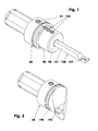
- the FIG. 1 shows as a first component of the modular interface a tool carrier (20) with an interchangeable tool holder (90) as a second component of the modular interface.
- the tool holder (90) carries as a tool (120), for example, an internal turning tool.
- the tool carrier (20) can be stored for example in the spindle of a tool unit. The corresponding spindle and the associated tool unit are not shown here.
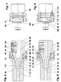
- This tensioning gear section (21), cf. FIG. 7 has a cylindrical outer wall (22), a cylindrical inner wall (23) - than Part of a tool holder (90) receiving recess (30) - and an eg planar end face (24).
- fitting holes (25) In the front or contact surface (24) are after FIG. 3 arranged four fitting holes (25), which, starting from the contact surface (24), for example, 2.7 mm deep.
- the narrow tolerated diameter of the fitting holes (25) is eg 6 mm.
- the center lines (26) of the fitting bores (25) lie on an imaginary cylinder whose center line coincides with the center line (39) of the tool carrier (20).
- the mutually parallel center lines (26) are equidistant distributed on the imaginary cylinder, which here has a diameter of 27.5 mm, distributed, see. also FIG. 18 ,
- the tensioning gear section (21) which adjoins the contact surface (24) has, with a tool carrier (20) with e.g. 50 mm outside diameter has a depth of e.g. 17.2 mm, while its wall thickness is e.g. Measures 9 mm.
- the inner wall (23) ends e.g. in front of a flat inner end face (28), in which a truncated cone-shaped portion (31) adjoins.
- This section (31) has here, e.g. a maximum diameter of 20 mm and a cone angle of 16 degrees. The length of this truncated cone-shaped portion (31) is approximately 14.2 mm.
- the section (31) is followed by an at least partially cylindrical bore (32). It ends before a e.g. truncated cone-shaped inner end face (29) into which, if necessary, a cooling and / or Schmierstoffzu Munichbohrung (35) opens.
- a sealing ring can be used, which seals the holes (32, 97) against each other.
- the tensioning gear portion (21) of the tool carrier (20) has, for example, two opposing bores (36, 38).
- FIG. 6 has the bore (36), for example, an internal thread, for example, the fine thread M 10 x 1.
- a special countersunk screw (40) is firmly screwed in the threaded hole (36).
- the countersunk head of this screw (40) which has a tool recess (42), is clamped against the depression of the threaded hole (36).
- the other end of the special countersunk screw (40) has an eg crowned, possibly spherically curved bearing journal (41), which projects into the recess (30).
- the diameter of the journal (41) is for example 6.5 mm.
- the eccentric shaft (51) has a smooth, cylindrical outer surface (52) which sits in a likewise smooth-walled bore (38) with little play or a transition fit.
- a partial annular groove (53) is incorporated in the central region of the outer surface (52) in the central region of the outer surface (52) has a partial annular groove (53) is incorporated.
- the Operaringnut (53) completely covers the lower half of the illustrated cross section.
- the tangential Operaringnutausset (54) are shown.
- the centers of the groove bottoms of Operaringnutausset (54) are almost parallel straight lines, since the full cross section of Operaringnut (53), for example, covers 185 degrees of the Exzenterwellen influencess.
- the sectionringnut (53) has in the right half of the cross section, for example, a circular section-shaped cross-section.
- the diameter of the circle belonging to this cross-section is for example 3.3 mm.
- the height of the circular segment-shaped cross section measures, for example, 39% of the circle diameter.
- the eccentric shaft (51) has a non-cylindrical eccentric pin (55) having an active displacement surface (46) and a passive abutment surface (47). To this end, he has across his axis (56) a non-circular cross-section, which consists of two circular sections that contact each other along their tendons. The diameter of the circular sections is eg 8 mm, while their arc height measures for example 2.25 mm. The eccentricity of the adjustment surface (46) is for example 0.8 mm. She is after FIG. 20 offset downwards from the center line (56). The eccentricity of the stop surface (47) measures 3.3 mm and is also offset from the center line (56) down.
- adjustment (46) and stop surfaces (47) at least partially spherical, barrel-shaped or spherically curved outer surfaces.
- the eccentric pin-free end face of the eccentric shaft (51) has a tool recess (57) with, for example, a hexagonal hollow cross-section. Between the tool recess (57) and the radial outer surface (52) extends, for example, a 0.5 mm deep groove (48) or notch for marking the position of the eccentric pin (51), cf. FIGS. 20 and 21 , The groove (48) sits behind FIG. 20 below the eccentric pin (51).
- the tool recess (57) of the eccentric shaft (51) is e.g. larger than the tool recess (42) of the special countersunk screw (40).
- the tool holder (90) In the recess (30) is stuck FIG. 6 the tool holder (90).
- the latter comprises a flange portion (91), a locking portion (100), a pin portion (110) and an end portion (112).
- the almost disk-shaped flange section (91) here has a cylindrical outer surface, the outer diameter of which corresponds, for example, to the adjacent outer diameter of the tool carrier (20).
- the flange section (91) has, for example, a plane end face (98), in the middle of which a cylindrical bore (92) for receiving the tool (120) is arranged.
- the tool (120) here an internal turning tool, is fixed via its shank (121) with three clamping screws (126) in the tool holder (90).
- the clamping screws (126) sit in corresponding threaded holes (125).
- the tool recesses of the clamping screws (126) have, for example, a smaller hollow cross-section than the tool recess (57) of the tool holder (90).
- the tool (120) can also be secured in the tool holder (90) by means of a transverse press fit or the like.
- a tool (190) in the form of an external turning tool inserted in the tool carrier (20) a tool (190) in the form of an external turning tool.
- This external turning tool (190) which carries an indexable insert (192) here, has an interface shape such that it can be adapted in a manner comparable to the tool holder (90) in the tool carrier (20).
- the back of the flange portion (91), cf. FIG. 5 has a planar end face (93), which serves as a contact surface for contacting the tool carrier (20).
- the end face (93) is optionally divided by even or odd grooves in different zones, so that there island-like contact surfaces arise whose respective surface area, for example, is only a few square millimeters.
- the contact surfaces (24) and (93), which have been machined to fit one another, can be truncated cone-shaped or spherically curved.
- the cone angle would then be between 170 and 190 degrees, while the radius of curvature would be greater than 200 mm.
- each fitting screws (117) are screwed.
- the tightly tolerated head diameter of the fitting screws (117) is eg 6 mm.
- the front or contact surface (93) is separated by a shaft shoulder (95).
- the latter has a flat ejection surface (96) and a truncated cone-shaped radial wall.
- the cone angle of the radial wall is e.g. 50 degrees.
- the flange portion (91) - viewed in the axial direction (1) - has e.g. a slightly larger wall thickness than in the region of the end face (93).
- the ejection surface (96) is followed by a short cylindrical section (102) having an annular groove (103) with e.g. cylindrical groove bottom (104).
- the groove bottom (104) has e.g. a diameter of 21.2 mm.
- the annular groove (103) has e.g. a frustoconical flank whose flank angle measures 30 degrees.
- the opposite groove flank has a flat flank surface.
- This flank surface belongs to two rear grip webs (105, 106).
- the rearward webs (105, 106) have e.g. a wall thickness of e.g. 3 mm. They cover each other in the circumferential direction, e.g. 60 degrees.
- Each rear grip web (105, 106) has a side flank in the circumferential direction, wherein the side flanks (107) of the rear grip webs (105, 106) are each aligned parallel to one another. You have a distance of 16 mm in the embodiment.
- the maximum diameter of the tool carrier (20) in the region of the rearward webs (105, 106) is e.g. 25.7 mm.
- cylindrical portion (102) may be replaced by a truncated cone shell.
- journal section (110) is connected downstream of the locking section (100).
- the latter comes in istchselem Tool holder (90) with the cylindrical end portion (112) of the tool carrier (20) in contact.
- the contact surface is defined as the first assembly joint (114).
- This assembly joint (114) which has a radial clearance of at least 0.05 mm, can also have the shape of a truncated cone, which then over a large area on the portion (31).
- the pin portion (110) can be completely eliminated.
- the rear end face (93) of the tool holder (90) lies on the front end face (24) of the tool carrier (20), e.g. over a large area.
- the resulting contact surface is referred to as the second mounting joint (94).
- the e.g. one-piece shift lever element (60) is arranged between the tensioning gear portion (21) of the tool carrier (20) and the locking portion (100) of the tool holder (90).
- the latter is oriented within the tool carrier (20) so that its front region faces the tool holder (90) or the tool (190).
- the shift lever element (60) is a ring, cf. FIGS. 4 . 22 and 23 , in which bore (61) in each case two inwardly projecting inner webs (71, 72) are arranged.
- the bore diameter is eg 26.6 mm.
- the radial outer surface of the shift lever member (60) has a largely cylindrical shape. Their diameter is eg 31 mm.
- the bore (61) has an inner wall taper (63) in the region of the small transverse bore (66) for the same reason.
- Both wall tapers are each in the form of a cylinder jacket part, the axis of this cylinder jacket being opposite to the center line (89) of the shift lever element (60), e.g. tilted by 7.5 degrees.
- Each of these webs (85, 86) has a Torusteilförmig curved surface. About this surface contacted the shift lever element (60), the inner wall (23) of the tool carrier (20).
- inner webs (71, 72) are arranged axially symmetrically to the shift lever element centerline (89).
- the leading edges (73) of the inner webs (71, 72) are frustoconical surfaces.
- the cone angle here is 120 degrees.
- the radial inner surfaces (74) are e.g. cylindrically curved.
- the shift lever element (60) has a diameter of e.g. 22.1 mm.
- Each inner land (71, 72) covers an angular range of e.g. 105 degrees.
- Both transverse bores (66, 68) of the shift lever element (60) are offset by approximately 90 degrees with respect to the centers of the inner webs (71, 72).
- To FIG. 22 has the transverse bore (68) shown on the right has a diameter of about 8 mm, while the transverse bore shown on the left (66) has a diameter of about 6.5 mm.
- the center line (69) of the transverse bore (68) crosses the center line (89) of the tension lever element (60) at a distance of approximately 0.07 mm. This offset allows one Stable clamping position of the eccentric shaft (51) with clamped tool holder (90).
- the transverse bores (66, 68) whose walls are e.g. may be domed or conically curved, also be recesses with non-circular cross-section.
- the rear end face (65) of the shift lever element (60), cf. FIG. 24 Has four projections (81-84), for example, at least 2 mm beyond the regular end face (65) survive.
- Each projection (81-84) each has a plane surface which is aligned normal to the center line (89).
- the projections (83, 84) are in the region of the inner webs (71, 72). Their faces each have an area of about 22 mm 2 .
- the transitions are realized by large radii.
- the e.g. 6 mm radii facilitate the meshing of the rear grip elements (105, 106) when inserting the tool holder (90).
- the front end face (64), cf. FIG. 22 has four tabs (75-78), which exceed the regular face level, for example by a maximum of 3.2 mm.
- the larger tabs (75, 77, 78) are, for example, 2 mm beyond the smaller tab (76).
- the plane end face of the tab (75) is oriented normal to the center line (89).
- the end faces of the two Ausdschreiblaschen (77, 78), whose surface area in each case has approximately 10 mm 2 are angled approximately centrally, for example FIG. 22 the respective right side of the end face, so the respective angled Range, opposite the left side by 7.5 degrees to the transverse bore (68) out drops.
- the assembly joint (94) is only shown in principle.
- This axially acting assembly joint (94) is cut by transverse to the axial direction (1) oriented assembly joints (14), which block the direction of movement of the tool holder (90) relative to the tool carrier (20) in the radial direction (2) and circumferential direction (3).
- the assembly joints (14) are realized in the exemplary embodiment by the heads (118) of the fitting screws (117) which are inserted in the fitting bores (25).
- the heads (118) are generally called solid structures.
- solid structures include cylinders, regular and irregular primers with four or more longitudinal edges, polygons, cones, pyramids, or other comparable geometry. These may possibly also be hollow.
- the fitting bores (25) are generally called hollow structures (12, 13). There are two types.
- the first type is a hollow structure (12) which surrounds the corresponding solid structure (11) in such a way that it is blocked both in the radial direction (2) and in the circumferential direction (3), cf. FIGS. 14, 16 and 18 , As an example serves the head (118), which is almost free of play and repeat accurate in the fitting hole (25).
- the second type of hollow structure (13) leaves the solid structure (11) a direction of movement, eg the radial (2) or the circumferential direction (3), open transversely to the axial direction (1).
- a hollow structure is, for example, a groove (13) into which a pin engages as a solid structure (11), cf. FIG. 15 ,
- the groove (13) prevents migration of the solid structure (11) in the circumferential direction.
- the hollow structures (13) may also be oval slots, channels, or channels, which may also be curved in the longitudinal direction.
- the tool carrier has two cylindrical hollow structures (12) into which fits precisely one solid structure (11) of the tool holder. Both pairs of structures (10) block the tool holder relative to the tool carrier transversely to the axial direction without degrees of freedom.
- the blocking directions (18) extend in the radial (2) and circumferential directions (3).
- FIG. 18 The same applies to the arrangement of the statically overdetermined pairs of structures (10) FIGS. 16 and 18 , The arrangement off FIG. 18 is realized in the embodiment.
- FIG. 15 two pairs of structures (10) are shown, of which the left has no translatory degree of freedom.
- the right structure pair (10) has one degree of freedom in the radial direction (2).
- the right full structure (11) can not pivot about the centerline of the left pair of structures.
- FIGS. 17 and 19 apply only to structure pairs (10), which consist of solid structures (11) and hollow structures (13), each with a transverse degree of freedom (17).
- the FIG. 17 shows a statically determined variant, while the arrangement of FIG. 19 is overdetermined.
- the structure pairs are not on a pitch circle.
- the assembly joint (94) in each case two paired hollow structures - as a group - two complementary arranged full structures positioned opposite.
- the assembly joint (94) e.g. two further grouped hollow structures arranged in pairs, each with a different distance between them, so in this assembly joint at least three different tool holder can be positioned on a tool carrier so that their mounting positions differ safely.
- the shift lever element (60) sits in the space between the tensioning gear portion (21) and the locking portion (100) so that the bearing pin (41) of the special countersunk screw (40) projects into the transverse bore (66), while the eccentric pin (55) the eccentric shaft (51) projects into the larger transverse bore (68), cf. FIGS. 6 and 8 ,
- the pin (41) sits with minimal play in the corresponding transverse bore (66).
- a transition fit is also conceivable here.
- the pin (55) of the eccentric shaft (51) lies behind FIG. 6 only with its adjustment surface (46) in the transverse bore (68).
- FIG. 6 the tool holder (90) firmly clamped in the tool carrier (20) is shown. Both parts (20, 90) contact each other free of play and repeatable in the assembly joints (24) and (114) and between the fitting screws (117) and the fitting holes (25).
- the shift lever element (60) is pressed firmly against the rear grip webs (105, 106) via the eccentric shaft (51) with its projections (83, 84), under an elastic intrinsic deformation, cf.
- FIG. 7 In the transverse bore (68) is thereby the adjustment surface (46) of the eccentric pin (55) in the left bore area.
- the end faces of the projections (83, 84) are flat against the rear grip webs (105, 106).
- the tension lever element (60) thus has the effect of a spring element which generates the clamping force of the interface.
- the spring force and the associated deformability are made possible by the special geometric design of the tension lever element (60).
- the eccentric shaft (51) is pivoted about its tool recess (57), for example, 185 degrees about its center line (56) in a counterclockwise rotation, cf. FIG. 8 ,
- the pivoting is deliberately limited by the shape of the partial ring groove (53), cf. FIGS. 20 and 21 ,
- the marking (48) of the eccentric shaft (51) is now facing the tool holder (90).
- In the transverse bore (68) now comes the adjustment surface (46) of the eccentric pin (55) only in the right bore area to the plant.
- the shift lever element (60) inevitably tilts to about 3.2 degrees to the right, wherein the pivot point of the pivoting movement is approximately in the center of the bearing pin (41) of the special countersunk screw (40).
- the projections (83, 84) of the rear grip webs (105, 106) have been solved.
- the ejection tabs (77, 78) have been applied to the flat ejection surface (96) of the tool holder (90) and moved centrically to the right by approximately 0.32 mm.
- the already pre-dissolved tool holder (90) is pulled by the operator, axially with only little effort, to the right, cf. FIGS. 10 and 11 .
- the shift lever member (60) pivots to the right by another approximately 4.3 degrees, so that the planes of the end surfaces of the projections (81-84) at an angle of, for example, 7.5 degrees to their from the FIGS. 6 and 7 take known position.
- the pivotal movement is created by the engagement of the rear grip webs (105, 106) on the projections (83, 84).
- the tilting movement of the shift lever member (60) is limited by striking the left portion of the transverse bore (68) on the stop surface (47) of the eccentric pin (55).
- the angled end regions of the ejection tabs (77, 78) also move in the direction of the ejection surface (96), but without contacting them due to the surface angulations.
- the tool holder (90) is pivoted by the operator 90 degrees to the right or left about its center line (99), so that the rear webs (105, 106) in the shift lever element (60) the two gaps between the inner webs (71, 72) can happen.
- the tool holder (90) can now be easily removed from the tool carrier (20).
- the insertion of the tool holder (90) in the tool carrier (20) takes place in the reverse order.
- the tool holder (90) is pushed into the tool carrier (20) until it stops, so that the rear grip webs (105, 106) pass between the inner webs (71, 72) behind the latter.
- the marking (48) of the eccentric shaft (51) faces the tool holder (90).
- the tool holder (90) is pivoted by approximately 90 degrees to the right or left and thereby pressed axially so that the heads (118) of the fitting screws (117) slide into the fitting holes (25). He now holds with play - but captive - in the recess (30).
- the eccentric shaft (51) is pivoted by 185 degrees to the right with a hexagon wrench. As soon as the eccentric shaft (51) has been pivoted by 180 degrees, the clamping force of the tensioning mechanism has reached its maximum. Upon further rotation by 5 more degrees, only then contacted the Colourringnutauslauf (54) of the eccentric shaft (51) the pivot stopper pin (58), the clamping force drops slightly again, because the adjustment surface (46) has exceeded its dead center.
- the eccentric shaft (51) in the transverse bore (38) in a stable, self-locking position.
- the transverse bore (68) is correspondingly offset by 0.07 mm from the center line (89) arranged.
- the two projections (83, 84) By pivoting the eccentric shaft, the two projections (83, 84) at the same time to the rear grip webs (105, 106) and pull uniformly and without any tilting the mounting joints (94).
- the tool holder (90) sits now backlash-free and repeatable in the tool carrier (20).
- the fitting screws (117) seated in the fitting bores (25) center the parts (20, 90) circumferentially against each other and transversely to the center line (99).
Landscapes
- Engineering & Computer Science (AREA)
- Mechanical Engineering (AREA)
- Gripping On Spindles (AREA)
- Clamps And Clips (AREA)
Applications Claiming Priority (1)
| Application Number | Priority Date | Filing Date | Title |
|---|---|---|---|
| DE201210011760 DE102012011760B4 (de) | 2012-06-15 | 2012-06-15 | Modulare Schnittstelle für Werkzeuge mit quer zur Axialrichtung wirkenden Strukturpaaren |
Publications (1)
| Publication Number | Publication Date |
|---|---|
| EP2674236A1 true EP2674236A1 (fr) | 2013-12-18 |
Family
ID=48699497
Family Applications (1)
| Application Number | Title | Priority Date | Filing Date |
|---|---|---|---|
| EP13003053.9A Withdrawn EP2674236A1 (fr) | 2012-06-15 | 2013-06-14 | Interface modulaire pour outils avec paires de structures actives perpendiculaires sur la direction axiale |
Country Status (2)
| Country | Link |
|---|---|
| EP (1) | EP2674236A1 (fr) |
| DE (1) | DE102012011760B4 (fr) |
Cited By (2)
| Publication number | Priority date | Publication date | Assignee | Title |
|---|---|---|---|---|
| EP3064300A1 (fr) * | 2015-03-05 | 2016-09-07 | Benz GmbH, Werkzeugsysteme | Interface modulaire pour outils rotatifs et fixes en rotation |
| CN111867763A (zh) * | 2019-02-26 | 2020-10-30 | 胡贝特·基米希 | 用于固定镗杆的装置 |
Citations (5)
| Publication number | Priority date | Publication date | Assignee | Title |
|---|---|---|---|---|
| EP0281760A2 (fr) * | 1987-03-11 | 1988-09-14 | Firma Gottlieb Gühring | Système d'accouplement pour outil coupant ayant un manchon |
| EP1768808B1 (fr) | 2004-07-16 | 2008-04-30 | Mirko Flam | Adaptateur d'outil |
| EP2301696A1 (fr) * | 2009-09-23 | 2011-03-30 | ESA Eppinger GmbH | Interface entre un corps de réception et un insert, l'insert étant notamment développé comme support d'outil ou de pièce à usiner |
| DE102010044273A1 (de) * | 2010-09-02 | 2012-03-08 | Jürgen Mettchen | Universalschnittstelle für die maschinelle spanabhebende Materialbearbeitung |
| EP2590769A2 (fr) * | 2010-07-05 | 2013-05-15 | Benz GmbH, Werkzeugsysteme | Interface modulaire pour outils |
-
2012
- 2012-06-15 DE DE201210011760 patent/DE102012011760B4/de active Active
-
2013
- 2013-06-14 EP EP13003053.9A patent/EP2674236A1/fr not_active Withdrawn
Patent Citations (6)
| Publication number | Priority date | Publication date | Assignee | Title |
|---|---|---|---|---|
| EP0281760A2 (fr) * | 1987-03-11 | 1988-09-14 | Firma Gottlieb Gühring | Système d'accouplement pour outil coupant ayant un manchon |
| EP1768808B1 (fr) | 2004-07-16 | 2008-04-30 | Mirko Flam | Adaptateur d'outil |
| EP2301696A1 (fr) * | 2009-09-23 | 2011-03-30 | ESA Eppinger GmbH | Interface entre un corps de réception et un insert, l'insert étant notamment développé comme support d'outil ou de pièce à usiner |
| EP2590769A2 (fr) * | 2010-07-05 | 2013-05-15 | Benz GmbH, Werkzeugsysteme | Interface modulaire pour outils |
| EP2590769B1 (fr) * | 2010-07-05 | 2017-11-22 | Benz GmbH, Werkzeugsysteme | Interface modulaire pour outils |
| DE102010044273A1 (de) * | 2010-09-02 | 2012-03-08 | Jürgen Mettchen | Universalschnittstelle für die maschinelle spanabhebende Materialbearbeitung |
Cited By (2)
| Publication number | Priority date | Publication date | Assignee | Title |
|---|---|---|---|---|
| EP3064300A1 (fr) * | 2015-03-05 | 2016-09-07 | Benz GmbH, Werkzeugsysteme | Interface modulaire pour outils rotatifs et fixes en rotation |
| CN111867763A (zh) * | 2019-02-26 | 2020-10-30 | 胡贝特·基米希 | 用于固定镗杆的装置 |
Also Published As
| Publication number | Publication date |
|---|---|
| DE102012011760A1 (de) | 2013-12-19 |
| DE102012011760B4 (de) | 2015-04-30 |
Similar Documents
| Publication | Publication Date | Title |
|---|---|---|
| EP0507147B1 (fr) | Accouplement | |
| EP3341149B1 (fr) | Plaquette de coupe, porte-outil et outil | |
| EP1924377B1 (fr) | Porte-outil exempt de vibrations | |
| DE102010052884C5 (de) | Werkzeugaggregat mit Exzenterspannvorrichtung | |
| DE10326928B4 (de) | Schnittstelle zwischen zwei Teilelementen eines Werkzeugsystems | |
| EP1044081B1 (fr) | Tete de fraisage dotee d'une plaquette a reglage unidimensionnel a tridimensionnel et d'une plaquette fixee par liaison de forme | |
| DE102010014322B4 (de) | Werkzeugkopf für ein rotierendes Werkzeug | |
| DE69928744T2 (de) | Fräser | |
| EP0674561A1 (fr) | Foret plein | |
| EP0284745B1 (fr) | Accouplement entre une tête d'outil et un porte-outil | |
| EP2590769B1 (fr) | Interface modulaire pour outils | |
| WO2019101943A1 (fr) | Outil d'usinage d'une pièce par enlèvement de copeaux | |
| WO2019121998A1 (fr) | Porte-outil de fraisage et outil de fraisage | |
| DE69126280T2 (de) | Werkzeughaltvorrichtung | |
| AT391644B (de) | Revolverkopf fuer eine drehmaschine und hierzu passende werkzeughalter | |
| DE102007043953B4 (de) | Spannvorrichtung zum axialen Spannen zweier voneinander lösbarer Maschinenbauteile | |
| DE102012011760B4 (de) | Modulare Schnittstelle für Werkzeuge mit quer zur Axialrichtung wirkenden Strukturpaaren | |
| EP0285704B1 (fr) | Système de serrage composé de plusieurs parties en particulier pour outils tournant rond | |
| WO2018029013A1 (fr) | Logement d'outil | |
| WO2005077575A2 (fr) | Procede d'usinage par enlevement de copeaux de trous de precision | |
| EP4063064B1 (fr) | Module de type retrofit pourvu de système de serrage | |
| EP3486035B1 (fr) | Système de fixation destiné à fixer un outil à un logement d'outil ainsi que clé d'outil associée | |
| CH499365A (de) | Spannfutter für Werkzeuge | |
| WO2017174055A2 (fr) | Outil de coupe pourvu d'un corps de coupe fixé de manière amovible à un corps support par une bride simple | |
| EP3142818B1 (fr) | Interface modulaire pour outils |
Legal Events
| Date | Code | Title | Description |
|---|---|---|---|
| PUAI | Public reference made under article 153(3) epc to a published international application that has entered the european phase |
Free format text: ORIGINAL CODE: 0009012 |
|
| AK | Designated contracting states |
Kind code of ref document: A1 Designated state(s): AL AT BE BG CH CY CZ DE DK EE ES FI FR GB GR HR HU IE IS IT LI LT LU LV MC MK MT NL NO PL PT RO RS SE SI SK SM TR |
|
| AX | Request for extension of the european patent |
Extension state: BA ME |
|
| 17P | Request for examination filed |
Effective date: 20140617 |
|
| RBV | Designated contracting states (corrected) |
Designated state(s): AL AT BE BG CH CY CZ DE DK EE ES FI FR GB GR HR HU IE IS IT LI LT LU LV MC MK MT NL NO PL PT RO RS SE SI SK SM TR |
|
| STAA | Information on the status of an ep patent application or granted ep patent |
Free format text: STATUS: EXAMINATION IS IN PROGRESS |
|
| 17Q | First examination report despatched |
Effective date: 20170202 |
|
| GRAP | Despatch of communication of intention to grant a patent |
Free format text: ORIGINAL CODE: EPIDOSNIGR1 |
|
| STAA | Information on the status of an ep patent application or granted ep patent |
Free format text: STATUS: GRANT OF PATENT IS INTENDED |
|
| INTG | Intention to grant announced |
Effective date: 20230405 |
|
| P01 | Opt-out of the competence of the unified patent court (upc) registered |
Effective date: 20230606 |
|
| STAA | Information on the status of an ep patent application or granted ep patent |
Free format text: STATUS: THE APPLICATION IS DEEMED TO BE WITHDRAWN |
|
| 18D | Application deemed to be withdrawn |
Effective date: 20230817 |