EP3142818B1 - Interface modulaire pour outils - Google Patents
Interface modulaire pour outils Download PDFInfo
- Publication number
- EP3142818B1 EP3142818B1 EP15736173.4A EP15736173A EP3142818B1 EP 3142818 B1 EP3142818 B1 EP 3142818B1 EP 15736173 A EP15736173 A EP 15736173A EP 3142818 B1 EP3142818 B1 EP 3142818B1
- Authority
- EP
- European Patent Office
- Prior art keywords
- assembly
- section
- pin
- interface according
- tool holder
- Prior art date
- Legal status (The legal status is an assumption and is not a legal conclusion. Google has not performed a legal analysis and makes no representation as to the accuracy of the status listed.)
- Active
Links
Images


Classifications
-
- B—PERFORMING OPERATIONS; TRANSPORTING
- B23—MACHINE TOOLS; METAL-WORKING NOT OTHERWISE PROVIDED FOR
- B23B—TURNING; BORING
- B23B31/00—Chucks; Expansion mandrels; Adaptations thereof for remote control
- B23B31/02—Chucks
- B23B31/10—Chucks characterised by the retaining or gripping devices or their immediate operating means
- B23B31/113—Retention by bayonet connection
-
- B—PERFORMING OPERATIONS; TRANSPORTING
- B23—MACHINE TOOLS; METAL-WORKING NOT OTHERWISE PROVIDED FOR
- B23B—TURNING; BORING
- B23B31/00—Chucks; Expansion mandrels; Adaptations thereof for remote control
- B23B31/02—Chucks
- B23B31/10—Chucks characterised by the retaining or gripping devices or their immediate operating means
-
- B—PERFORMING OPERATIONS; TRANSPORTING
- B23—MACHINE TOOLS; METAL-WORKING NOT OTHERWISE PROVIDED FOR
- B23B—TURNING; BORING
- B23B2231/00—Details of chucks, toolholder shanks or tool shanks
- B23B2231/12—Chucks having means to amplify the force produced by the actuating means to increase the clamping force
-
- B—PERFORMING OPERATIONS; TRANSPORTING
- B23—MACHINE TOOLS; METAL-WORKING NOT OTHERWISE PROVIDED FOR
- B23B—TURNING; BORING
- B23B2231/00—Details of chucks, toolholder shanks or tool shanks
- B23B2231/52—Chucks with means to loosely retain the tool or workpiece in the unclamped position
-
- B—PERFORMING OPERATIONS; TRANSPORTING
- B23—MACHINE TOOLS; METAL-WORKING NOT OTHERWISE PROVIDED FOR
- B23B—TURNING; BORING
- B23B31/00—Chucks; Expansion mandrels; Adaptations thereof for remote control
- B23B31/003—Work or tool ejection means
Definitions
- the invention relates to an interface according to the preamble of claim 1 consisting of a first assembly - holding a tool or a tool holder - and a second assembly - carrying a processing element, the first assembly having, on the one hand, a recess which has at least one truncated cone or cylindrical shell Section and on the other hand has a contact surface or contact point acting in the axial direction - in the direction of the second assembly - and the second assembly has a pin which, on the one hand, has a conical, truncated cone or cylindrical section for contact with the truncated cone or cylindrical section of the first assembly and, on the other hand, has at least one contact point or contact surface acting in the axial direction for contacting the contact surface or contact point of the first assembly.
- Such an interface is from the WO 2010/089405 A1 known.
- An annular shift lever element is arranged in a longitudinally displaceable or pivotable manner in the recess of the first assembly.
- the shift lever element has at least one articulation element - which articulates the second assembly.
- the second assembly has at least one rear grip element, which can be brought behind the articulation element of the shift lever element by a pivoting movement of the second assembly.
- a coupling for coupling a tool shaft to a machine shaft in which a more secure, easily releasable axial clamping and a secure cutting edge orientation can be achieved and tools with a screw connection can also be used.
- the machine shaft has a sleeve with a central bore for receiving a complementary end of the tool shaft.
- the sleeve has a flat outer edge and an inner section for centering the tool shank and a second outer section with opposite sectors with recessed oblique ramps.
- the tool shaft can be locked in a bayonet-like manner in the machine shaft, with the tool shaft with its flat flange against the flat edge of the sleeve and thus forms a tight, rigid unit that can withstand high torques resulting from the cutting work.
- the present invention is based on the problem of developing an interface from a first assembly and a second assembly which ensures easy handling with a high repeatability with regard to the position of the second assembly relative to the first assembly with each tool change - despite the small interface size.
- a bayonet-like closure with at least one web on the pin is arranged between the recess and the pin.
- a clamping element is arranged in the first assembly, the front end of which comes into contact with one of the webs during clamping.
- a second assembly is positioned so that it cannot rotate relative to a first assembly and is clamped with repeat accuracy.
- the solution is a bayonet-type lock.
- the second assembly which can be plugged into the first assembly, carries radially projecting elements such as webs, bolts, pins or the like.
- the first assembly has corresponding recesses or rear grips into which the protruding elements engage with one another under at least one translational and/or rotational movement when the two assemblies are coupled.
- the protruding elements contact the recesses or rear grips, for example in point, line or area-shaped contacts.
- the first assembly also houses a clamping element, with the help of which the coupling movement is supported and/or the coupling is locked. If necessary, the uncoupling process can also be initiated using the manually operated clamping element, for example.
- the protruding elements and the recesses or rear grips are mutually arranged in such a way that when uncoupling the second assembly cannot immediately fall out of the first after a first unclamping or releasing of the coupling. Another step is required to completely separate the assemblies.
- the first assembly is a rotating spindle head of a tool changing unit.
- the second assembly represents a tool-carrying tool holder.
- the first assembly can also be a non-rotating tool carrier, such as is used, for example, as a steel holder for an upper slide of a conventional lathe.
- the second assembly in this case is the in Turning steel arranged in a tool holder as a tool or cutting edge carrier.
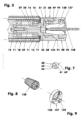
- the Figure 3 shows the front part of a tool unit.
- a spindle head (20) protrudes from its housing (10) as the first assembly of a modular interface.
- a replaceable tool holder (90) sits in the spindle head (20) as a second component of the modular interface.
- the tool holder (90) carries a twist drill, for example, as a tool (140).
- the housing (10) and the cover (13) support the rear end of the spindle head (20) in two shoulder ball bearings (11) arranged in an O-arrangement.
- the outer rings of the shoulder ball bearings (11) are axially fixed between the housing (10) and the cover (13).
- the inner rings of the bearings (11) mounted on the shaft (39) of the spindle head (20) are seated axially clamped between a spindle head shoulder (25) and a holding plate (12) which is axially screwed centrally to the spindle head (20) and centered in the inner ring of the contacted inclined shoulder bearing (11).
- the cover (13) of the housing (10) has an annular groove (16) on the front of its largely flat end face (15), in which a sealing ring (17) resting on the rear flat collar surface (26) of the spindle head (20) is inserted is.
- a tubular clamping gear section (21) protrudes from the housing (10) at the front of the spindle head (20).
- This tensioning gear section (21) has, for example, a cylindrical outer wall (22), cf. Figure 1 , a profiled inner wall (31) - as part of a recess (30) receiving a tool holder (90) - and a front, for example flat, end face (124).
- the depth of the clamping gear section (21) is 11.7 mm for a spindle head (20) with, for example, 22 mm outer diameter, while its average wall thickness is, for example, 4 mm.
- the inner wall (31) ends, for example, in front of a flat intermediate floor surface (28), in which a cylindrical bore (35) adjoins.
- This hole (35) has a diameter of 6 mm, for example.
- the depth of the hole (35) is approx. 2.8 mm.
- the hole (35) ends in a flat floor surface (29).
- the clamping gear section (21) of the spindle head (20) has, for example, a radial threaded bore (49), cf. Figure 21 .
- the threaded hole (49) has a fine thread M 8 x 0.5.
- the inner wall (31) is based on a central bore, the cylindrical wall of which has an inner diameter of, for example, 12 mm, cf. Figure 5 .
- a first milling (42) the cylinder jacket (43) of which covers the entire third quadrant.
- a quadrant is a term from mathematics. It is a section of a drawing plane bounded by two coordinate axes. Four quadrants cover 360 degrees, with the zero degree marking in the positive area of the abscissa of the coordinate system. The angle degrees are counted counterclockwise.
- the first milling (42) of the inner wall (31) has a radius of, for example, 4.5 mm. Its center line (45) is 3.6 mm from the center line (59). She's lying down Figure 5 at 225 degrees in the third quadrant.
- a second cutout (46) is opposite the first (42). It has the shape of a crescent-shaped elongated hole. The center line of the slot lies on a circle with a radius of 4.1 mm. The bore diameter of the elongated hole is 4 mm.
- the second cutout (46) covers, for example, 116.6 degrees of angle in the area of the full slot width. Both cutouts (42, 46) extend parallel to the center line (59) between the flat intermediate floor surface (28) and the outer cone section (120). In the second quadrant there is a slot (47) between the cutouts (42, 46).
- Another stud, the locking stud (48) is arranged between the cutouts (46, 42) in the fourth quadrant.
- the holding groove (51) has a clamping flank (52) which lies opposite the intermediate floor surface (28). It is, for example, a section of a thread groove flank whose pitch is, for example, 6 mm. In the exemplary embodiment it is part of a rectangular thread. It can also be part of a trapezoidal, saw, round, metric thread or the like.
- the retaining groove (51) covers approx. 60 degrees of angle the circumference of the inner wall (31).
- the maximum holding groove depth is, for example, 2.1 mm.
- the retaining groove (51) has a non-loaded flank (53), which is, for example, 3 mm away from the clamping flank (52). If necessary, the retaining groove (51) can extend to the intermediate floor surface (28) without the flank (53).
- An eccentric screw (60) equipped with an external thread is screwed into the threaded hole (49) of the clamping gear section (21). It has a front end which projects into the recess (30) and is designed as an eccentric pin (65), see also Figure 7 .
- the latter has a cylindrical outer surface with a diameter of, for example, 4.8 mm. If necessary, this outer surface can also be convex, for example spherically curved, at least in some areas.
- the eccentricity of the eccentric pin (65) is, for example, 0.875 ⁇ 0.1 mm.
- the pivot axis of the eccentric screw (60) is its center line (69).
- the eccentric pin-free end face of the eccentric screw (60) has a tool recess (67), cf. Figure 20 , for example with a hexagonal hollow cross section. Between the tool recess (67) and the external thread of the eccentric screw (60), a groove (68) or notch, for example 0.5 mm deep, extends in the radial direction to mark the position of the eccentric shaft (61), cf. Figure 2 .
- the groove (68) is seated Figure 2 below the tool recess (67).
- the tool holder (90) is located in the recess (30).
- the latter has a flange section (91), cf. Figure 11 , on which a pin (100) is formed.
- This pin (100) comprises an outer cone section (120), a locking section (101) and an end section (127).
- the almost disc-shaped flange section (91) has a cylindrical outer surface, the diameter of which is, for example, slightly smaller than the adjacent outer diameter of the spindle head (20).
- the flange section (91) has, for example, a flat end face (95), in the middle of which a recess (95) is arranged for receiving a collet chuck (130), another tool-holding component or a tool itself.
- the flange section (91) ends in a contact surface (121) designed as a flat collar surface.
- the outer surface of the flange section (91) points close to the collar surface (121), cf. Figure 21 , a marking groove (122).
- the collet recess (95) in the end face (92) essentially comprises an internal thread section (96) and an internal cone section (97).
- the 6.5 mm deep internal thread section (96) for example, has the fine thread M18 x 1.
- the inner cone section (97) has a cone angle of, for example, 16 degrees with a maximum inner diameter of 11 mm. It is 12 mm deep. It opens into a central, e.g. 4.5 mm long through-threaded hole (98), which has an M3 thread.
- a through hole can be used instead of the threaded through hole (98).
- the back of the flange section (91) has, for example, a flat end face (121) which serves as a contact surface for contacting the spindle head (20).
- the end face (93) may be divided into different zones by even or odd grooves. It is possible that the end faces (24) and (121), which are machined to match one another, have the shape of a truncated cone or be spherically curved. The cone angle would then be between 170 and 190 degrees, while the radius of curvature would be greater than 200 mm.
- the outer cone section (120) is connected downstream of the flange section (91).
- the contact surface is defined as the first assembly joint (124).
- This assembly joint (124) can also have the shape of a cylinder jacket.
- the collar surface (121) of the tool holder (90) also rests, for example over a large area, on the front end surface (24) of the spindle head (20).
- the resulting contact surface is referred to as the second assembly joint (94).
- a contact surface can meet one or more point or line-like contact points.
- the spindle head (20) has the flat end face (24), while the flange section (91) of the tool holder (90), for example, has a single contact point.
- the point contact point can also be on the spindle head (20) and the full-surface collar surface (121) on the tool holder (90).
- the locking section (101) adjoins the outer cone section (120) via the flat collar surface (121), see also Figures 2 and 4 .
- the locking section (101) is built on a base cylinder (103), which only has a cylindrical basic shape, for example.
- the base cylinder (103), for example, has a length of 9 mm and a diameter of 11 mm. It ends in a flat floor surface (104).
- a bayonet element (106), an ejection bar (111) and a closing bar (115) are formed or attached to the base cylinder (103).
- the heads of the bayonet element (106), the ejection bar (111) and the closing bar (115) lie on an envelope cylinder (105), the diameter of which is, for example, 15.2 mm, see Figure 4.
- an imaginary cylinder In the area between the outer wall of the base cylinder (103 ) and the envelope cylinder (105) there is an imaginary cylinder called a partial cylinder (70). Its diameter is, for example, 14 mm.
- the partial cylinder (70) is in the Figures 12 to 20 shown in unrolled form as part of the spindle head (20) and the tool holder (90).
- the bayonet element (106) is, for example, a section of a threaded web whose pitch is, for example, 6 mm.
- the bayonet element (106) shown in the exemplary embodiment is part of a rectangular thread. It can also be part of a trapezoidal, saw, round, metric thread or the like.
- the bayonet element (106) covers an average of 40 degrees of the partial cylinder circumference.
- the bridge width is 2 mm, while the bridge height measures 2.1 mm.
- the center or center of gravity of the bayonet element (106) is 2.5 mm away from the base surface (104).
- the bayonet element (106) can also be designed as a plate-like web, the axially oriented surfaces of which are flat and not helically shaped.
- the clamping flank (52) would have to be replaced by a spherical, e.g. spherical, curved contact surface.
- the ejection bar (111) is offset counterclockwise by, for example, 120 degrees. He has one - measured on the partial cylinder (70) - average width of 4.25 mm. Its height is 6 mm.
- the lower end face of the ejection web (111) ends at the bottom surface (104). In the top view, cf. Figure 2 and the Figures 12 to 20 , for example, it has a rectangular outer contour.
- the locking bar (115) is positioned a further 60 degrees counterclockwise. The latter has a maximum width of 4.3 mm and a maximum height of 3.4 mm. Its lower end face also ends at the bottom surface (104), cf. Figure 6 .
- the closing bar (115) and the ejection bar (111) have two opposing flat side surfaces (116, 112) which form planes parallel to one another, cf. also Figure 6 .
- the side surface (116) of the closing bar (115) is from one side to the next Figure 6
- the horizontal central longitudinal plane (5) is 1 mm away, while the distance between the central longitudinal plane (5) and the side surface (112) of the ejection web (111) is 2.5 mm.
- a flat surface (113) which is oriented parallel to the center line (99) and perpendicular to the side surfaces (112, 116). It has to the central longitudinal plane (6), cf. Figure 4 , a distance of e.g. 5.6 mm.
- a rounding (117) is incorporated into the closing bar (115), which has a radius of 3.4 mm.
- the perpendicular to the drawing plane of the Figure 6 The aligned center line (119) of the fillet (117) is 4.7 mm away from the bottom surface (104). At the same time it is 0.4 mm above the central longitudinal plane (5).
- the end section (127) is a substantially cylindrical section which ends in a 0.5 x 30° chamfer. In the axial direction There is a clearance of, for example, 0.2 mm between the end section (127) and the bottom surface (29).
- FIGS. 10 and 11 show the interface consisting of the spindle head (20) and the tool holder (90) in longitudinal and cross section. In cross section, cf. Figure 10 , the partial cylinder (70) is shown in dash-dotted lines. The partial cylinder (70) is penetrated by the raised, radially inwardly projecting parts of the inner wall (31) of the spindle head (20) and the radially outwardly projecting parts (106, 111, 115) of the tool holder (90).
- a tool holder development is created.
- the latter is referred to as internal processing (71).
- a spindle development is created. It is referred to as external development (72).
- the beginning (A), the end (B) and the direction of the developments (71, 72) are in the Figures 12 and 13 shown.
- the development (71) is positioned in front of the development (72) so that the bayonet element (106) of the development (71) is located approximately in the middle in front of the first milling (42).
- the tool holder (90) is inserted linearly into the spindle head (20).
- the rear collar surface (121) comes into contact with the end surface (24).
- the bayonet element (106) is located in the first cutout (42). If the tool holder (90) is now moved by turning the spindle head (20) to the right, the bayonet element (106) is inserted into the retaining groove (51), cf. Figure 14 .
- the bayonet element (106) After further turning the eccentric screw (60) by approx. 45 degrees, the bayonet element (106) has rested with its clamping flank (107) on the clamping flank (52) of the retaining groove (51), cf. Figure 17 . Now the tool holder (90) is clamped in the spindle head (20) at two points or lines or surfaces that are almost opposite each other. On the one hand, the bayonet element (106) resting in the retaining groove (51) pulls the rear collar surface (121) against the end face (24) of the spindle head (20). On the other hand, a comparable clamping effect results from the contact of the eccentric pin (65) on the locking bar (115).
- the eccentric screw (60) is moved from the back by turning it to the left, cf. Figure 18 .
- the movement is a clockwise rotation.
- the eccentric pin (65) contacts the ejection bar (111).
- the bayonet element (106) is released from the clamping flank (52) of the retaining groove (51).
- the locking bar (115) abuts against the eccentric pin (65), which has been pivoted completely back, for example, before the bayonet element (106) has completely left the retaining groove (51).
- the tool holder (90) is in a blocked position with play, cf. Figure 19 .
- the tool holder (90) were mounted overhead in a vertically positioned spindle head (20) that is open at the bottom, it could not fall out of the spindle head (20) despite the clamping being released.
- the tool holder (90) In order to be able to clamp or couple the tool holder (90) in the spindle head (20), it is first positioned before insertion so that its marking groove (122), see Figure (21), is opposite the marking groove (57) of the spindle head ( 20) is arranged. It is then inserted into the spindle head (20) in a straight line movement. As soon as resistance is felt in the axial direction, the tool holder (90) is pivoted approximately 65 to 75 degrees to the right so that the bayonet element (106) pivots into the retaining groove (52). Thus, when clamping or coupling, at least one of the webs (106, 115) can be brought into contact with at least one rear grip of the recess (30).
- the eccentric screw (60) is swiveled clockwise by, for example, 225 degrees using a torque wrench. For example, 10 Nm is selected as the maximum torque.
- the eccentric pin (65) rests on the locking bar (115) and pivots the tool holder (90) further by a few degrees or minutes.
- the eccentric pin (65) pushes the bayonet element (106) deeper into the retaining groove (52).
- the eccentric pin (65) also presses the tool holder (90) into the assembly joints (94) and (124) due to its contact with the closing bar (115). Since the fine thread of the eccentric screw (60) sits self-locking in the hole (49) due to its large contact surface in the thread and due to its low thread pitch, the eccentric screw (60) holds its position.
- the tool holder (90) can also be clamped in the spindle head (20) with path or angle control, cf. Figures 2 , 21 and 22 .
- path or angle control cf. Figures 2 , 21 and 22 .
- use the eccentric screw (60), its marking groove (68), cf. Figures 2 , 21 and 22 initially lies in front of the centerline-parallel marking groove (57) of the spindle head (20), cf. Figure 2 , pivoted in a clockwise rotation in front of the other marking groove (58) of the spindle head (20), see Figure 21.
- the closely tolerated contact of the end section (127) on the tool holder side in the bore (35) of the spindle head (20) also supports a uniform, tilt-free contact of the components (20, 90) in the assembly joints (94) and (124).
- the tool holder (90) now sits in the spindle head (20) without play and with repeat accuracy.
Landscapes
- Engineering & Computer Science (AREA)
- Mechanical Engineering (AREA)
- Gripping On Spindles (AREA)
- Jigs For Machine Tools (AREA)
Claims (9)
- Interface composée d'un premier ensemble (20) portant un outil ou un porte-outil, et d'un second ensemble (90) portant un élément d'usinage,- dans laquelle le premier ensemble (20) possède d'une part un évidement (30), qui comprend au moins une section (32) de forme tronconique ou cylindrique et présente d'autre part une surface d'appui (24) ou un point de contact agissant dans la direction axiale, en direction du second ensemble (90),- dans laquelle le second ensemble (90) comprend un tourillon (100), qui possède d'une part une section (120) de forme conique, tronconique ou cylindrique pour s'appliquer contre la section (32) de forme tronconique ou cylindrique du premier ensemble (20), et présente d'autre part au moins un point de contact ou une surface d'appui (121) agissant dans la direction axiale pour entrer en contact avec la surface d'appui (24) ou le point de contact du premier ensemble (20),- dans laquelle une fermeture en forme de baïonnette avec au moins une traverse (106, 115), présente sur le tourillon (100), est disposée entre l'évidement (30) et le tourillon (100),caractérisée en ce queun élément de serrage (60) est disposé dans le premier ensemble (20) dont l'extrémité avant vient s'appliquer contre l'une des traverses (106, 115) lors du serrage,et en ce que l'élément de serrage (60) est une vis excentrique.
- Interface selon la revendication 1, caractérisée en ce qu'au moins une des traverses (106, 115) est un élément de baïonnette en forme de section filetée présentant une inclinaison de 5 à 8 mm et ayant une longueur couvrant 10 à 60 degrés du tour de 360 degrés.
- Interface selon la revendication 2, caractérisée en ce que l'élément de baïonnette (106) monte à droite.
- Interface selon la revendication 2, caractérisée en ce que la section transversale de l'élément de baïonnette (106) est un rectangle, un trapèze ou un triangle, dans laquelle le côté de base le plus long dans le cas du trapèze se situe à la surface de tourillon.
- Interface selon la revendication 1, caractérisée en ce que le tourillon (100) présente comme troisième traverse (111) une traverse d'éjection contre le flanc (112) de laquelle, tourné vers la vis excentrique (60), la vis excentrique (60) vient s'appliquer lors du desserrage du second sous-ensemble (20).
- Interface selon la revendication 1, caractérisée en ce que la vis excentrique (60) comprend un tourillon excentrique (65) et nécessite un angle de pivotement de 180 à 270 degrés entre une position de desserrage et une position de serrage.
- Interface selon la revendication 1, caractérisée en ce que la distance située entre les traverses (106) et (115) est inférieure au diamètre extérieur du tourillon excentrique (65) de la vis excentrique (60).
- Interface selon la revendication 1, caractérisée en ce que la zone arrière de l'évidement (30) du premier ensemble (20), permettant de recevoir un boulon cylindrique (127) du second ensemble (90), présente un alésage cylindrique (35), dans lequel le jeu entre le boulon (127) et l'alésage (35) est inférieur à 0,1 mm.
- Interface selon la revendication 1, caractérisée en ce que le premier ensemble (20) est une tête de broche, tandis que le second ensemble (90) est un porte-outil.
Applications Claiming Priority (2)
| Application Number | Priority Date | Filing Date | Title |
|---|---|---|---|
| DE102014007056.5A DE102014007056B3 (de) | 2014-05-15 | 2014-05-15 | Modulare Schnittstelle II für Werkzeuge |
| PCT/DE2015/000216 WO2015172760A1 (fr) | 2014-05-15 | 2015-05-05 | Interface modulaire pour outils |
Publications (3)
| Publication Number | Publication Date |
|---|---|
| EP3142818A1 EP3142818A1 (fr) | 2017-03-22 |
| EP3142818B1 true EP3142818B1 (fr) | 2023-10-04 |
| EP3142818B8 EP3142818B8 (fr) | 2023-11-08 |
Family
ID=53045739
Family Applications (1)
| Application Number | Title | Priority Date | Filing Date |
|---|---|---|---|
| EP15736173.4A Active EP3142818B8 (fr) | 2014-05-15 | 2015-05-05 | Interface modulaire pour outils |
Country Status (4)
| Country | Link |
|---|---|
| US (1) | US10239126B2 (fr) |
| EP (1) | EP3142818B8 (fr) |
| DE (1) | DE102014007056B3 (fr) |
| WO (1) | WO2015172760A1 (fr) |
Families Citing this family (1)
| Publication number | Priority date | Publication date | Assignee | Title |
|---|---|---|---|---|
| CN114714284B (zh) * | 2022-05-10 | 2022-09-16 | 广东省源天工程有限公司 | 一种基于bim的机电管线装配装置 |
Family Cites Families (7)
| Publication number | Priority date | Publication date | Assignee | Title |
|---|---|---|---|---|
| US3444781A (en) * | 1967-10-19 | 1969-05-20 | Sonnet Tool & Mfg Co | Tool holder |
| US5667228A (en) * | 1995-06-20 | 1997-09-16 | Fabris; Mario | Quick change mandrel for an engine lathe etc |
| DE10219599B4 (de) * | 2002-05-02 | 2004-08-19 | Esa Eppinger Gmbh | Werkzeugspanneinrichtung |
| US8360699B2 (en) * | 2007-01-04 | 2013-01-29 | Stojan Stojanovski | Cutting tool assembly with an eccentric drive member |
| DE102009003455A1 (de) * | 2009-02-09 | 2010-08-19 | Johne & Co. Präzisionswerkzeuge GmbH | Kupplung für Rotationswerkzeug |
| IL203798A (en) * | 2010-02-08 | 2013-03-24 | Iscar Ltd | Clamping mechanism |
| DE102010026129B4 (de) * | 2010-07-05 | 2013-07-11 | Benz GmbH Werkzeugsysteme | Modulare Schnittstelle für Werkzeuge |
-
2014
- 2014-05-15 DE DE102014007056.5A patent/DE102014007056B3/de active Active
-
2015
- 2015-05-05 WO PCT/DE2015/000216 patent/WO2015172760A1/fr not_active Ceased
- 2015-05-05 EP EP15736173.4A patent/EP3142818B8/fr active Active
-
2016
- 2016-11-12 US US15/350,043 patent/US10239126B2/en active Active
Also Published As
| Publication number | Publication date |
|---|---|
| EP3142818B8 (fr) | 2023-11-08 |
| EP3142818A1 (fr) | 2017-03-22 |
| US20170209938A1 (en) | 2017-07-27 |
| US10239126B2 (en) | 2019-03-26 |
| DE102014007056B3 (de) | 2015-05-28 |
| WO2015172760A1 (fr) | 2015-11-19 |
Similar Documents
| Publication | Publication Date | Title |
|---|---|---|
| DE865561C (de) | Werkzeugkopf | |
| DE69122094T2 (de) | Werkzeughalter mit einem radialwechselmechanismus | |
| DE69818247T2 (de) | Winkeleinstellbares anfaswerkzeug | |
| DE3030909C2 (fr) | ||
| DE60101981T2 (de) | Schneidwerkzeughalter | |
| DE102017104914B4 (de) | Anschlag für ein Bohr-, Fräs- oder Senkwerkzeug | |
| EP2301696A1 (fr) | Interface entre un corps de réception et un insert, l'insert étant notamment développé comme support d'outil ou de pièce à usiner | |
| DE3433878A1 (de) | Axial-spannverbindung | |
| DE19736891A1 (de) | Schlüsselloses Bohrfutter | |
| DE1602717B2 (de) | Schnellwechsel-werkzeughalter | |
| EP2590769B1 (fr) | Interface modulaire pour outils | |
| DE1924321B2 (de) | Spannfutter für Werkstücke an Werkzeugmaschinen | |
| DE4123966A1 (de) | Spannvorrichtung fuer einzelwerkzeuge | |
| EP3142818B1 (fr) | Interface modulaire pour outils | |
| EP0247410A2 (fr) | Accouplement à relier la tête-outil et le porte-outils à des machines-outils | |
| DE69215905T2 (de) | Spannvorrichtung für fräser oder ähnliche, anpassbar für verschiedene haltergrössen | |
| EP1896207A1 (fr) | Interface d'un systeme d'outillage | |
| EP3064300B1 (fr) | Interface modulaire pour outils rotatifs et fixes en rotation | |
| DE102008008335B4 (de) | Werkzeug zur spanenden Bearbeitung von Werkstücken | |
| DE3320874C2 (fr) | ||
| CH499365A (de) | Spannfutter für Werkzeuge | |
| DE102012011760B4 (de) | Modulare Schnittstelle für Werkzeuge mit quer zur Axialrichtung wirkenden Strukturpaaren | |
| EP0301185A1 (fr) | Dispositif de serrage pour outils d'usinage comme tarauds, fraises ou semblables, spécialement outils fabriqués entièrement en métal dur | |
| EP1445050A1 (fr) | Adaptateur pour un outil | |
| CH707765A2 (de) | Bearbeitbarer Rohling für die Herstellung eines rotierenden oder stehenden Werkzeugs. |
Legal Events
| Date | Code | Title | Description |
|---|---|---|---|
| STAA | Information on the status of an ep patent application or granted ep patent |
Free format text: STATUS: THE INTERNATIONAL PUBLICATION HAS BEEN MADE |
|
| PUAI | Public reference made under article 153(3) epc to a published international application that has entered the european phase |
Free format text: ORIGINAL CODE: 0009012 |
|
| STAA | Information on the status of an ep patent application or granted ep patent |
Free format text: STATUS: REQUEST FOR EXAMINATION WAS MADE |
|
| 17P | Request for examination filed |
Effective date: 20161208 |
|
| AK | Designated contracting states |
Kind code of ref document: A1 Designated state(s): AL AT BE BG CH CY CZ DE DK EE ES FI FR GB GR HR HU IE IS IT LI LT LU LV MC MK MT NL NO PL PT RO RS SE SI SK SM TR |
|
| AX | Request for extension of the european patent |
Extension state: BA ME |
|
| RIN1 | Information on inventor provided before grant (corrected) |
Inventor name: GIESSLER, WILHELM Inventor name: GEISSELMANN, THOMAS Inventor name: ZELLER, CHRISTOPH Inventor name: NEUMANN, ANDREAS Inventor name: GANTER, SIMON |
|
| DAV | Request for validation of the european patent (deleted) | ||
| DAX | Request for extension of the european patent (deleted) | ||
| STAA | Information on the status of an ep patent application or granted ep patent |
Free format text: STATUS: EXAMINATION IS IN PROGRESS |
|
| 17Q | First examination report despatched |
Effective date: 20190930 |
|
| GRAP | Despatch of communication of intention to grant a patent |
Free format text: ORIGINAL CODE: EPIDOSNIGR1 |
|
| STAA | Information on the status of an ep patent application or granted ep patent |
Free format text: STATUS: GRANT OF PATENT IS INTENDED |
|
| INTG | Intention to grant announced |
Effective date: 20230418 |
|
| P01 | Opt-out of the competence of the unified patent court (upc) registered |
Effective date: 20230606 |
|
| GRAS | Grant fee paid |
Free format text: ORIGINAL CODE: EPIDOSNIGR3 |
|
| GRAA | (expected) grant |
Free format text: ORIGINAL CODE: 0009210 |
|
| STAA | Information on the status of an ep patent application or granted ep patent |
Free format text: STATUS: THE PATENT HAS BEEN GRANTED |
|
| REG | Reference to a national code |
Ref legal event code: R108 Ref document number: 502015016622 Country of ref document: DE Ref country code: DE |
|
| AK | Designated contracting states |
Kind code of ref document: B1 Designated state(s): AL AT BE BG CH CY CZ DE DK EE ES FI FR GB GR HR HU IE IS IT LI LT LU LV MC MK MT NL NO PL PT RO RS SE SI SK SM TR |
|
| REG | Reference to a national code |
Ref country code: GB Ref legal event code: FG4D Free format text: NOT ENGLISH |
|
| REG | Reference to a national code |
Ref country code: CH Ref legal event code: PK Free format text: BERICHTIGUNG B8 Ref country code: CH Ref legal event code: EP |
|
| REG | Reference to a national code |
Ref country code: IE Ref legal event code: FG4D Free format text: LANGUAGE OF EP DOCUMENT: GERMAN |
|
| RBV | Designated contracting states (corrected) |
Designated state(s): AL AT BE BG CH CY CZ DK EE ES FI FR GB GR HR HU IE IS IT LI LT LU LV MC MK MT NL NO PL PT RO RS SE SI SK SM TR |
|
| REG | Reference to a national code |
Ref country code: DE Ref legal event code: R107 Ref document number: 502015016622 Country of ref document: DE |
|
| REG | Reference to a national code |
Ref country code: LT Ref legal event code: MG9D |
|
| REG | Reference to a national code |
Ref country code: NL Ref legal event code: MP Effective date: 20231004 |
|
| PG25 | Lapsed in a contracting state [announced via postgrant information from national office to epo] |
Ref country code: NL Free format text: LAPSE BECAUSE OF FAILURE TO SUBMIT A TRANSLATION OF THE DESCRIPTION OR TO PAY THE FEE WITHIN THE PRESCRIBED TIME-LIMIT Effective date: 20231004 |
|
| PG25 | Lapsed in a contracting state [announced via postgrant information from national office to epo] |
Ref country code: GR Free format text: LAPSE BECAUSE OF FAILURE TO SUBMIT A TRANSLATION OF THE DESCRIPTION OR TO PAY THE FEE WITHIN THE PRESCRIBED TIME-LIMIT Effective date: 20240105 |
|
| PG25 | Lapsed in a contracting state [announced via postgrant information from national office to epo] |
Ref country code: IS Free format text: LAPSE BECAUSE OF FAILURE TO SUBMIT A TRANSLATION OF THE DESCRIPTION OR TO PAY THE FEE WITHIN THE PRESCRIBED TIME-LIMIT Effective date: 20240204 |
|
| PG25 | Lapsed in a contracting state [announced via postgrant information from national office to epo] |
Ref country code: LT Free format text: LAPSE BECAUSE OF FAILURE TO SUBMIT A TRANSLATION OF THE DESCRIPTION OR TO PAY THE FEE WITHIN THE PRESCRIBED TIME-LIMIT Effective date: 20231004 |
|
| PG25 | Lapsed in a contracting state [announced via postgrant information from national office to epo] |
Ref country code: ES Free format text: LAPSE BECAUSE OF FAILURE TO SUBMIT A TRANSLATION OF THE DESCRIPTION OR TO PAY THE FEE WITHIN THE PRESCRIBED TIME-LIMIT Effective date: 20231004 |
|
| PG25 | Lapsed in a contracting state [announced via postgrant information from national office to epo] |
Ref country code: LT Free format text: LAPSE BECAUSE OF FAILURE TO SUBMIT A TRANSLATION OF THE DESCRIPTION OR TO PAY THE FEE WITHIN THE PRESCRIBED TIME-LIMIT Effective date: 20231004 Ref country code: IS Free format text: LAPSE BECAUSE OF FAILURE TO SUBMIT A TRANSLATION OF THE DESCRIPTION OR TO PAY THE FEE WITHIN THE PRESCRIBED TIME-LIMIT Effective date: 20240204 Ref country code: GR Free format text: LAPSE BECAUSE OF FAILURE TO SUBMIT A TRANSLATION OF THE DESCRIPTION OR TO PAY THE FEE WITHIN THE PRESCRIBED TIME-LIMIT Effective date: 20240105 Ref country code: ES Free format text: LAPSE BECAUSE OF FAILURE TO SUBMIT A TRANSLATION OF THE DESCRIPTION OR TO PAY THE FEE WITHIN THE PRESCRIBED TIME-LIMIT Effective date: 20231004 Ref country code: BG Free format text: LAPSE BECAUSE OF FAILURE TO SUBMIT A TRANSLATION OF THE DESCRIPTION OR TO PAY THE FEE WITHIN THE PRESCRIBED TIME-LIMIT Effective date: 20240104 Ref country code: PT Free format text: LAPSE BECAUSE OF FAILURE TO SUBMIT A TRANSLATION OF THE DESCRIPTION OR TO PAY THE FEE WITHIN THE PRESCRIBED TIME-LIMIT Effective date: 20240205 |
|
| PG25 | Lapsed in a contracting state [announced via postgrant information from national office to epo] |
Ref country code: SE Free format text: LAPSE BECAUSE OF FAILURE TO SUBMIT A TRANSLATION OF THE DESCRIPTION OR TO PAY THE FEE WITHIN THE PRESCRIBED TIME-LIMIT Effective date: 20231004 Ref country code: RS Free format text: LAPSE BECAUSE OF FAILURE TO SUBMIT A TRANSLATION OF THE DESCRIPTION OR TO PAY THE FEE WITHIN THE PRESCRIBED TIME-LIMIT Effective date: 20231004 Ref country code: PL Free format text: LAPSE BECAUSE OF FAILURE TO SUBMIT A TRANSLATION OF THE DESCRIPTION OR TO PAY THE FEE WITHIN THE PRESCRIBED TIME-LIMIT Effective date: 20231004 Ref country code: NO Free format text: LAPSE BECAUSE OF FAILURE TO SUBMIT A TRANSLATION OF THE DESCRIPTION OR TO PAY THE FEE WITHIN THE PRESCRIBED TIME-LIMIT Effective date: 20240104 Ref country code: LV Free format text: LAPSE BECAUSE OF FAILURE TO SUBMIT A TRANSLATION OF THE DESCRIPTION OR TO PAY THE FEE WITHIN THE PRESCRIBED TIME-LIMIT Effective date: 20231004 Ref country code: HR Free format text: LAPSE BECAUSE OF FAILURE TO SUBMIT A TRANSLATION OF THE DESCRIPTION OR TO PAY THE FEE WITHIN THE PRESCRIBED TIME-LIMIT Effective date: 20231004 |
|
| PG25 | Lapsed in a contracting state [announced via postgrant information from national office to epo] |
Ref country code: DK Free format text: LAPSE BECAUSE OF FAILURE TO SUBMIT A TRANSLATION OF THE DESCRIPTION OR TO PAY THE FEE WITHIN THE PRESCRIBED TIME-LIMIT Effective date: 20231004 |
|
| PG25 | Lapsed in a contracting state [announced via postgrant information from national office to epo] |
Ref country code: CZ Free format text: LAPSE BECAUSE OF FAILURE TO SUBMIT A TRANSLATION OF THE DESCRIPTION OR TO PAY THE FEE WITHIN THE PRESCRIBED TIME-LIMIT Effective date: 20231004 |
|
| PG25 | Lapsed in a contracting state [announced via postgrant information from national office to epo] |
Ref country code: SK Free format text: LAPSE BECAUSE OF FAILURE TO SUBMIT A TRANSLATION OF THE DESCRIPTION OR TO PAY THE FEE WITHIN THE PRESCRIBED TIME-LIMIT Effective date: 20231004 |
|
| PG25 | Lapsed in a contracting state [announced via postgrant information from national office to epo] |
Ref country code: SM Free format text: LAPSE BECAUSE OF FAILURE TO SUBMIT A TRANSLATION OF THE DESCRIPTION OR TO PAY THE FEE WITHIN THE PRESCRIBED TIME-LIMIT Effective date: 20231004 Ref country code: SK Free format text: LAPSE BECAUSE OF FAILURE TO SUBMIT A TRANSLATION OF THE DESCRIPTION OR TO PAY THE FEE WITHIN THE PRESCRIBED TIME-LIMIT Effective date: 20231004 Ref country code: RO Free format text: LAPSE BECAUSE OF FAILURE TO SUBMIT A TRANSLATION OF THE DESCRIPTION OR TO PAY THE FEE WITHIN THE PRESCRIBED TIME-LIMIT Effective date: 20231004 Ref country code: IT Free format text: LAPSE BECAUSE OF FAILURE TO SUBMIT A TRANSLATION OF THE DESCRIPTION OR TO PAY THE FEE WITHIN THE PRESCRIBED TIME-LIMIT Effective date: 20231004 Ref country code: EE Free format text: LAPSE BECAUSE OF FAILURE TO SUBMIT A TRANSLATION OF THE DESCRIPTION OR TO PAY THE FEE WITHIN THE PRESCRIBED TIME-LIMIT Effective date: 20231004 Ref country code: DK Free format text: LAPSE BECAUSE OF FAILURE TO SUBMIT A TRANSLATION OF THE DESCRIPTION OR TO PAY THE FEE WITHIN THE PRESCRIBED TIME-LIMIT Effective date: 20231004 Ref country code: CZ Free format text: LAPSE BECAUSE OF FAILURE TO SUBMIT A TRANSLATION OF THE DESCRIPTION OR TO PAY THE FEE WITHIN THE PRESCRIBED TIME-LIMIT Effective date: 20231004 |
|
| PLBE | No opposition filed within time limit |
Free format text: ORIGINAL CODE: 0009261 |
|
| STAA | Information on the status of an ep patent application or granted ep patent |
Free format text: STATUS: NO OPPOSITION FILED WITHIN TIME LIMIT |
|
| 26N | No opposition filed |
Effective date: 20240705 |
|
| PG25 | Lapsed in a contracting state [announced via postgrant information from national office to epo] |
Ref country code: SI Free format text: LAPSE BECAUSE OF FAILURE TO SUBMIT A TRANSLATION OF THE DESCRIPTION OR TO PAY THE FEE WITHIN THE PRESCRIBED TIME-LIMIT Effective date: 20231004 |
|
| PG25 | Lapsed in a contracting state [announced via postgrant information from national office to epo] |
Ref country code: SI Free format text: LAPSE BECAUSE OF FAILURE TO SUBMIT A TRANSLATION OF THE DESCRIPTION OR TO PAY THE FEE WITHIN THE PRESCRIBED TIME-LIMIT Effective date: 20231004 |
|
| PG25 | Lapsed in a contracting state [announced via postgrant information from national office to epo] |
Ref country code: MC Free format text: LAPSE BECAUSE OF FAILURE TO SUBMIT A TRANSLATION OF THE DESCRIPTION OR TO PAY THE FEE WITHIN THE PRESCRIBED TIME-LIMIT Effective date: 20231004 |
|
| PG25 | Lapsed in a contracting state [announced via postgrant information from national office to epo] |
Ref country code: LU Free format text: LAPSE BECAUSE OF NON-PAYMENT OF DUE FEES Effective date: 20240505 |
|
| GBPC | Gb: european patent ceased through non-payment of renewal fee |
Effective date: 20240505 |
|
| PG25 | Lapsed in a contracting state [announced via postgrant information from national office to epo] |
Ref country code: MC Free format text: LAPSE BECAUSE OF FAILURE TO SUBMIT A TRANSLATION OF THE DESCRIPTION OR TO PAY THE FEE WITHIN THE PRESCRIBED TIME-LIMIT Effective date: 20231004 Ref country code: LU Free format text: LAPSE BECAUSE OF NON-PAYMENT OF DUE FEES Effective date: 20240505 |
|
| REG | Reference to a national code |
Ref country code: BE Ref legal event code: MM Effective date: 20240531 |
|
| PG25 | Lapsed in a contracting state [announced via postgrant information from national office to epo] |
Ref country code: IE Free format text: LAPSE BECAUSE OF NON-PAYMENT OF DUE FEES Effective date: 20240505 |
|
| PG25 | Lapsed in a contracting state [announced via postgrant information from national office to epo] |
Ref country code: BE Free format text: LAPSE BECAUSE OF NON-PAYMENT OF DUE FEES Effective date: 20240531 |
|
| PG25 | Lapsed in a contracting state [announced via postgrant information from national office to epo] |
Ref country code: FR Free format text: LAPSE BECAUSE OF NON-PAYMENT OF DUE FEES Effective date: 20240531 |
|
| PG25 | Lapsed in a contracting state [announced via postgrant information from national office to epo] |
Ref country code: GB Free format text: LAPSE BECAUSE OF NON-PAYMENT OF DUE FEES Effective date: 20240505 |
|
| REG | Reference to a national code |
Ref country code: AT Ref legal event code: MM01 Ref document number: 1617234 Country of ref document: AT Kind code of ref document: T Effective date: 20240505 |
|
| PGFP | Annual fee paid to national office [announced via postgrant information from national office to epo] |
Ref country code: CH Payment date: 20250601 Year of fee payment: 11 |
|
| PG25 | Lapsed in a contracting state [announced via postgrant information from national office to epo] |
Ref country code: AT Free format text: LAPSE BECAUSE OF NON-PAYMENT OF DUE FEES Effective date: 20240505 |
|
| PG25 | Lapsed in a contracting state [announced via postgrant information from national office to epo] |
Ref country code: CY Free format text: LAPSE BECAUSE OF FAILURE TO SUBMIT A TRANSLATION OF THE DESCRIPTION OR TO PAY THE FEE WITHIN THE PRESCRIBED TIME-LIMIT; INVALID AB INITIO Effective date: 20150505 |
|
| PG25 | Lapsed in a contracting state [announced via postgrant information from national office to epo] |
Ref country code: HU Free format text: LAPSE BECAUSE OF FAILURE TO SUBMIT A TRANSLATION OF THE DESCRIPTION OR TO PAY THE FEE WITHIN THE PRESCRIBED TIME-LIMIT; INVALID AB INITIO Effective date: 20150505 |
|
| PG25 | Lapsed in a contracting state [announced via postgrant information from national office to epo] |
Ref country code: FI Free format text: LAPSE BECAUSE OF FAILURE TO SUBMIT A TRANSLATION OF THE DESCRIPTION OR TO PAY THE FEE WITHIN THE PRESCRIBED TIME-LIMIT Effective date: 20231004 |