EP2674559A2 - Agencement d'actionnement de porte - Google Patents
Agencement d'actionnement de porte Download PDFInfo
- Publication number
- EP2674559A2 EP2674559A2 EP13002574.5A EP13002574A EP2674559A2 EP 2674559 A2 EP2674559 A2 EP 2674559A2 EP 13002574 A EP13002574 A EP 13002574A EP 2674559 A2 EP2674559 A2 EP 2674559A2
- Authority
- EP
- European Patent Office
- Prior art keywords
- guide rail
- damping elements
- door
- elements
- türbetätigeranordnung
- Prior art date
- Legal status (The legal status is an assumption and is not a legal conclusion. Google has not performed a legal analysis and makes no representation as to the accuracy of the status listed.)
- Withdrawn
Links
Images

Classifications
-
- E—FIXED CONSTRUCTIONS
- E05—LOCKS; KEYS; WINDOW OR DOOR FITTINGS; SAFES
- E05F—DEVICES FOR MOVING WINGS INTO OPEN OR CLOSED POSITION; CHECKS FOR WINGS; WING FITTINGS NOT OTHERWISE PROVIDED FOR, CONCERNED WITH THE FUNCTIONING OF THE WING
- E05F5/00—Braking devices, e.g. checks; Stops; Buffers
- E05F5/06—Buffers or stops limiting opening of swinging wings, e.g. floor or wall stops
-
- E—FIXED CONSTRUCTIONS
- E05—LOCKS; KEYS; WINDOW OR DOOR FITTINGS; SAFES
- E05F—DEVICES FOR MOVING WINGS INTO OPEN OR CLOSED POSITION; CHECKS FOR WINGS; WING FITTINGS NOT OTHERWISE PROVIDED FOR, CONCERNED WITH THE FUNCTIONING OF THE WING
- E05F5/00—Braking devices, e.g. checks; Stops; Buffers
-
- E—FIXED CONSTRUCTIONS
- E05—LOCKS; KEYS; WINDOW OR DOOR FITTINGS; SAFES
- E05F—DEVICES FOR MOVING WINGS INTO OPEN OR CLOSED POSITION; CHECKS FOR WINGS; WING FITTINGS NOT OTHERWISE PROVIDED FOR, CONCERNED WITH THE FUNCTIONING OF THE WING
- E05F5/00—Braking devices, e.g. checks; Stops; Buffers
- E05F5/02—Braking devices, e.g. checks; Stops; Buffers specially for preventing the slamming of swinging wings during final closing movement, e.g. jamb stops
-
- E—FIXED CONSTRUCTIONS
- E05—LOCKS; KEYS; WINDOW OR DOOR FITTINGS; SAFES
- E05C—BOLTS OR FASTENING DEVICES FOR WINGS, SPECIALLY FOR DOORS OR WINDOWS
- E05C17/00—Devices for holding wings open; Devices for limiting opening of wings or for holding wings open by a movable member extending between frame and wing; Braking devices, stops or buffers, combined therewith
- E05C17/02—Devices for holding wings open; Devices for limiting opening of wings or for holding wings open by a movable member extending between frame and wing; Braking devices, stops or buffers, combined therewith by mechanical means
- E05C17/04—Devices for holding wings open; Devices for limiting opening of wings or for holding wings open by a movable member extending between frame and wing; Braking devices, stops or buffers, combined therewith by mechanical means with a movable bar or equivalent member extending between frame and wing
- E05C17/12—Devices for holding wings open; Devices for limiting opening of wings or for holding wings open by a movable member extending between frame and wing; Braking devices, stops or buffers, combined therewith by mechanical means with a movable bar or equivalent member extending between frame and wing consisting of a single rod
- E05C17/24—Devices for holding wings open; Devices for limiting opening of wings or for holding wings open by a movable member extending between frame and wing; Braking devices, stops or buffers, combined therewith by mechanical means with a movable bar or equivalent member extending between frame and wing consisting of a single rod pivoted at one end, and with the other end running along a guide member
- E05C17/28—Devices for holding wings open; Devices for limiting opening of wings or for holding wings open by a movable member extending between frame and wing; Braking devices, stops or buffers, combined therewith by mechanical means with a movable bar or equivalent member extending between frame and wing consisting of a single rod pivoted at one end, and with the other end running along a guide member with braking, clamping or securing means at the connection to the guide member
-
- E—FIXED CONSTRUCTIONS
- E05—LOCKS; KEYS; WINDOW OR DOOR FITTINGS; SAFES
- E05F—DEVICES FOR MOVING WINGS INTO OPEN OR CLOSED POSITION; CHECKS FOR WINGS; WING FITTINGS NOT OTHERWISE PROVIDED FOR, CONCERNED WITH THE FUNCTIONING OF THE WING
- E05F3/00—Closers or openers with braking devices, e.g. checks; Construction of pneumatic or liquid braking devices
- E05F3/22—Additional arrangements for closers, e.g. for holding the wing in opened or other position
- E05F2003/228—Arrangements where the end of the closer arm is sliding in a track
-
- E—FIXED CONSTRUCTIONS
- E05—LOCKS; KEYS; WINDOW OR DOOR FITTINGS; SAFES
- E05F—DEVICES FOR MOVING WINGS INTO OPEN OR CLOSED POSITION; CHECKS FOR WINGS; WING FITTINGS NOT OTHERWISE PROVIDED FOR, CONCERNED WITH THE FUNCTIONING OF THE WING
- E05F15/00—Power-operated mechanisms for wings
- E05F15/60—Power-operated mechanisms for wings using electrical actuators
- E05F15/603—Power-operated mechanisms for wings using electrical actuators using rotary electromotors
- E05F15/611—Power-operated mechanisms for wings using electrical actuators using rotary electromotors for swinging wings
- E05F15/63—Power-operated mechanisms for wings using electrical actuators using rotary electromotors for swinging wings operated by swinging arms
- E05F2015/631—Power-operated mechanisms for wings using electrical actuators using rotary electromotors for swinging wings operated by swinging arms the end of the arm sliding in a track; Slider arms therefor
-
- E—FIXED CONSTRUCTIONS
- E05—LOCKS; KEYS; WINDOW OR DOOR FITTINGS; SAFES
- E05F—DEVICES FOR MOVING WINGS INTO OPEN OR CLOSED POSITION; CHECKS FOR WINGS; WING FITTINGS NOT OTHERWISE PROVIDED FOR, CONCERNED WITH THE FUNCTIONING OF THE WING
- E05F3/00—Closers or openers with braking devices, e.g. checks; Construction of pneumatic or liquid braking devices
- E05F3/22—Additional arrangements for closers, e.g. for holding the wing in opened or other position
- E05F3/227—Additional arrangements for closers, e.g. for holding the wing in opened or other position mounted at the top of wings, e.g. details related to closer housings, covers, end caps or rails therefor
-
- E—FIXED CONSTRUCTIONS
- E05—LOCKS; KEYS; WINDOW OR DOOR FITTINGS; SAFES
- E05Y—INDEXING SCHEME ASSOCIATED WITH SUBCLASSES E05D AND E05F, RELATING TO CONSTRUCTION ELEMENTS, ELECTRIC CONTROL, POWER SUPPLY, POWER SIGNAL OR TRANSMISSION, USER INTERFACES, MOUNTING OR COUPLING, DETAILS, ACCESSORIES, AUXILIARY OPERATIONS NOT OTHERWISE PROVIDED FOR, APPLICATION THEREOF
- E05Y2201/00—Constructional elements; Accessories therefor
- E05Y2201/40—Motors; Magnets; Springs; Weights; Accessories therefor
- E05Y2201/47—Springs
- E05Y2201/48—Leaf or leg springs
-
- E—FIXED CONSTRUCTIONS
- E05—LOCKS; KEYS; WINDOW OR DOOR FITTINGS; SAFES
- E05Y—INDEXING SCHEME ASSOCIATED WITH SUBCLASSES E05D AND E05F, RELATING TO CONSTRUCTION ELEMENTS, ELECTRIC CONTROL, POWER SUPPLY, POWER SIGNAL OR TRANSMISSION, USER INTERFACES, MOUNTING OR COUPLING, DETAILS, ACCESSORIES, AUXILIARY OPERATIONS NOT OTHERWISE PROVIDED FOR, APPLICATION THEREOF
- E05Y2201/00—Constructional elements; Accessories therefor
- E05Y2201/60—Suspension or transmission members; Accessories therefor
- E05Y2201/622—Suspension or transmission members elements
- E05Y2201/684—Rails; Tracks
-
- E—FIXED CONSTRUCTIONS
- E05—LOCKS; KEYS; WINDOW OR DOOR FITTINGS; SAFES
- E05Y—INDEXING SCHEME ASSOCIATED WITH SUBCLASSES E05D AND E05F, RELATING TO CONSTRUCTION ELEMENTS, ELECTRIC CONTROL, POWER SUPPLY, POWER SIGNAL OR TRANSMISSION, USER INTERFACES, MOUNTING OR COUPLING, DETAILS, ACCESSORIES, AUXILIARY OPERATIONS NOT OTHERWISE PROVIDED FOR, APPLICATION THEREOF
- E05Y2600/00—Mounting or coupling arrangements for elements provided for in this subclass
- E05Y2600/40—Mounting location; Visibility of the elements
-
- E—FIXED CONSTRUCTIONS
- E05—LOCKS; KEYS; WINDOW OR DOOR FITTINGS; SAFES
- E05Y—INDEXING SCHEME ASSOCIATED WITH SUBCLASSES E05D AND E05F, RELATING TO CONSTRUCTION ELEMENTS, ELECTRIC CONTROL, POWER SUPPLY, POWER SIGNAL OR TRANSMISSION, USER INTERFACES, MOUNTING OR COUPLING, DETAILS, ACCESSORIES, AUXILIARY OPERATIONS NOT OTHERWISE PROVIDED FOR, APPLICATION THEREOF
- E05Y2800/00—Details, accessories and auxiliary operations not otherwise provided for
- E05Y2800/20—Combinations of elements
- E05Y2800/21—Combinations of elements of identical elements, e.g. of identical compression springs
-
- E—FIXED CONSTRUCTIONS
- E05—LOCKS; KEYS; WINDOW OR DOOR FITTINGS; SAFES
- E05Y—INDEXING SCHEME ASSOCIATED WITH SUBCLASSES E05D AND E05F, RELATING TO CONSTRUCTION ELEMENTS, ELECTRIC CONTROL, POWER SUPPLY, POWER SIGNAL OR TRANSMISSION, USER INTERFACES, MOUNTING OR COUPLING, DETAILS, ACCESSORIES, AUXILIARY OPERATIONS NOT OTHERWISE PROVIDED FOR, APPLICATION THEREOF
- E05Y2800/00—Details, accessories and auxiliary operations not otherwise provided for
- E05Y2800/20—Combinations of elements
- E05Y2800/22—Combinations of elements of not identical elements of the same category, e.g. combinations of not identical springs
-
- E—FIXED CONSTRUCTIONS
- E05—LOCKS; KEYS; WINDOW OR DOOR FITTINGS; SAFES
- E05Y—INDEXING SCHEME ASSOCIATED WITH SUBCLASSES E05D AND E05F, RELATING TO CONSTRUCTION ELEMENTS, ELECTRIC CONTROL, POWER SUPPLY, POWER SIGNAL OR TRANSMISSION, USER INTERFACES, MOUNTING OR COUPLING, DETAILS, ACCESSORIES, AUXILIARY OPERATIONS NOT OTHERWISE PROVIDED FOR, APPLICATION THEREOF
- E05Y2800/00—Details, accessories and auxiliary operations not otherwise provided for
- E05Y2800/34—Form stability
- E05Y2800/342—Deformable
- E05Y2800/35—Deformable of specific parts
-
- E—FIXED CONSTRUCTIONS
- E05—LOCKS; KEYS; WINDOW OR DOOR FITTINGS; SAFES
- E05Y—INDEXING SCHEME ASSOCIATED WITH SUBCLASSES E05D AND E05F, RELATING TO CONSTRUCTION ELEMENTS, ELECTRIC CONTROL, POWER SUPPLY, POWER SIGNAL OR TRANSMISSION, USER INTERFACES, MOUNTING OR COUPLING, DETAILS, ACCESSORIES, AUXILIARY OPERATIONS NOT OTHERWISE PROVIDED FOR, APPLICATION THEREOF
- E05Y2800/00—Details, accessories and auxiliary operations not otherwise provided for
- E05Y2800/67—Materials; Strength alteration thereof
- E05Y2800/676—Plastics
- E05Y2800/678—Elastomers
-
- E—FIXED CONSTRUCTIONS
- E05—LOCKS; KEYS; WINDOW OR DOOR FITTINGS; SAFES
- E05Y—INDEXING SCHEME ASSOCIATED WITH SUBCLASSES E05D AND E05F, RELATING TO CONSTRUCTION ELEMENTS, ELECTRIC CONTROL, POWER SUPPLY, POWER SIGNAL OR TRANSMISSION, USER INTERFACES, MOUNTING OR COUPLING, DETAILS, ACCESSORIES, AUXILIARY OPERATIONS NOT OTHERWISE PROVIDED FOR, APPLICATION THEREOF
- E05Y2900/00—Application of doors, windows, wings or fittings thereof
- E05Y2900/10—Application of doors, windows, wings or fittings thereof for buildings or parts thereof
- E05Y2900/13—Type of wing
- E05Y2900/132—Doors
Definitions
- the present invention relates to a Matbetuschigeran extract for moving a door leaf.
- the invention relates to the damping of the door leaf in the end position.
- Door operator assemblies typically include a door actuator configured as a door operator, door closer or power door closer, a guide rail having a moving member guided therein, and a lever connecting the door operator and the moving member.
- the moving element and the guide rail can also be referred to as a slider and slide rail.
- the door operator is fixed either fixed to the wall or frame or directly to the door leaf. If, for example, the door operator is located on the door leaf, the force is transmitted from the output shaft of the door operator via the lever to the movement element.
- the moving element is guided linearly movable in the guide rail, which is fixed to the wall or frame. In the end position of the door leaf, the movement of the moving element and thus also the movement of the door leaf itself can be damped.
- a Mosbet2011igeran Aunt for moving a door leaf comprising: (i) a longitudinally extending guide rail, (ii) a linearly movably guided in the guide rail moving element, (iii) a door operator with an output shaft, (iv) a lever (v) a stop fixedly arranged with respect to the guide rail, and (vi) a damper assembly in the guide rail between the stopper and the moving element, the damper assembly being composed of a juxtaposition of elastically deformable damping elements.
- a plurality of identical damping elements are assembled to the juxtaposition.
- at least three identical damping elements are used in the damper assembly according to the invention.
- damping elements which are lined up, has the advantage that the damper assembly can be made very long and slender. Furthermore, by selecting the damper hardness and the number of damping elements, the damping effect can be adjusted. If, in order to achieve a very narrow and physically small construction of the arrangement, the conventional damping element would simply be longer and narrower, the damping element would buckle and buckle. To avoid this, a plurality of elastically deformable damping elements are arranged one behind the other in the guide rail according to the invention. All damping elements are added linearly movable in the longitudinal direction. According to the invention, the damping elements are "elastically deformable". This means that the damping elements deform in the usually occurring in Schotuschigeranowski forces and thus dampen the movement of the moving element and the door leaf,
- the guide rail comprises at least one guide channel, wherein in the guide rail guided elements are movable by a positive reception in the guide channel only in the longitudinal direction.
- the guided in the guide channels elements can thus not be taken perpendicular to the longitudinal direction.
- all damping elements are guided in the guide channel.
- the guide rail comprises two parallel guide channels and the damping elements have on both sides each have a sliding wing. With these Gleitulateln the damping elements are guided in the two guide channels and thus can only be moved in the longitudinal direction.
- the stop may also have sliding wings and be guided in the guide channels.
- a screw and / or a bolt for fastening the stopper is preferably provided.
- This screw and / or the bolt pass through the stop and through the guide rail and engage in the underlying construction.
- the stop is anchored not only in the guide rail but also opposite the underlying construction. This is necessary especially for very heavy doors.
- a further screw such as a grub screw, can be provided in the stop. By means of this additional screw the stop is clamped in the guide rail to facilitate mounting.
- the guide rail preferably has a mounting surface, wherein the mounting surface comes to rest on the door, the frame or the wall. A mecanicsschierlen endeavor is perpendicular to this mounting surface Are defined.
- the damping elements and / or the movement element can protrude slightly beyond the guide rail in the direction perpendicular to the mounting surface. It is preferably provided that the number and size of the damping elements is chosen so large, so that the supernatant is at most 20%, preferably at most 10%, of the guide rail height.
- the damper assembly is assembled by an alternating juxtaposition of elastically deformable damping elements and elastically non-deformable shock elements, wherein at least two damping elements and a shock element arranged between the two damping elements are provided.
- impact elements and damping elements are alternately arranged between the stop and the movement element.
- All Dämpfurigs- and shock elements are added linearly movable in the longitudinal direction in the guide rail.
- the shock elements are "elastically non-deformable". This means that the impact elements do not deform, at least in the case of the forces occurring in a door actuator arrangement,
- the damping elements and the impact elements each have a concave side and a convex side. In the juxtaposition, each concave side abuts on a convex side.
- the surfaces with which the damping elements and the impact elements adjoin one another are therefore not perpendicular to the longitudinal direction but curved concave or convex.
- under a convex side is also an "arrow-shaped" Design to understand.
- the arrow-shaped configuration has two mutually converging flanks, which then meet either pointed or rounded. Similarly, the converging flanks can also meet on a stump. It is crucial that the force transmission surface between the damping element and the impact element is formed as large as possible. Particularly preferably, the individual elements are always adjacent to each other over the entire surface.
- the damping elements are formed as elastomer blocks, preferably as foamed elastomer blocks.
- the damping elements are designed as leaf springs. It is provided in particular that at least two of the leaf springs are arranged in the juxtaposition with different orientation. This means that in the case of a leaf spring the convex side points towards the moving element and the other side shows the concave side to the moving element.
- the leaf springs can all be made individually and loosely strung together in the guide rail. Alternatively, it is also possible to connect together several or all leaf springs outside the guide rail, for example by spot welding or by gluing, and then insert a whole battery of leaf springs in the guide rail. In a third possibility, several can Leaf springs are made in one piece. This is possible, for example, by injection molding a plurality of plastic leaf springs.
- the stringing is formed by a concertina-like spring.
- this accordion-like spring is made of bent sheet metal.
- the individual legs of the accordion-like spring form the individual damping elements.
- the invention allows a very narrow design in the direction perpendicular to the mounting surface.
- the damping effect of the damping arrangement can be adjusted by using different damping elements.
- the position of the end position of the door leaf is adjustable by a continuous adjustment of the stop.
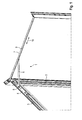
- Fig. 1 shows the door operator assembly 1 integrated into a door frame 2 and a door leaf frame 3.
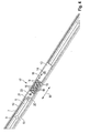
- Fig. 2 a guide rail 7 of the door actuator assembly 1 is shown in detail.
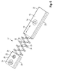
- Fig. 3 shows a frontal view Fig. 2 ,
- the door operator assembly 1 comprises a door operator 4, designed as a door closer with an output shaft 5.
- the door operator 4 is integrated in the door leaf frame 3.
- the guide rail 7 is integrated in the door frame 2.
- An upper, horizontal portion of the door frame 2 is hidden for clarity.
- a lever 6 is rotatably connected to one end with the output shaft 5.
- the guide rail 7 extends along a longitudinal direction 16.
- the guide rail 7 has a mounting surface 8 with mounting holes 9, About these mounting holes 9, the guide rail 7 is screwed into the door frame 2.
- the mounting holes 9 and mounting pin can protrude from the mounting surface 8.
- Perpendicular to the mounting surface 8 are two spaced side walls 10, each with a paragraph 11.
- the paragraphs 11 are parallel and spaced from the mounting surface 8.
- On the inside of the side walls is in each case a guide channel 12 of the guide rail 7 trained. In these guide channels 12, various elements in the guide rail 7 can be guided linearly movable. Due to the positive reception in the guide channels 12 only a movement in the longitudinal direction 16 is possible.
- a moving element 13 is guided linearly movable.
- a movement direction 15 of the movement element 13 corresponds to the longitudinal direction 16.
- An eye 14 is formed in the movement element 13. About this eye 14, the lever 6 is rotatably connected to the moving member 13.
- a stop 20 is fixed in the guide rail 7.
- the stop 20 is fixedly arranged with respect to the guide rail 7 via a first screw 21 and a second screw 22.
- Fig. 3 shows that the first screw 21, designed as a countersunk screw, extends through the mounting surface 8 and thus anchors the stop 20 with respect to the underlying structure.
- the damper assembly 17 is composed of an alternating juxtaposition of damping elements 18 and shock elements 19.
- the damping elements 18 are formed of foamed elastomer and are thus elastically deformable.
- the shock elements 19 are either made of metal or hard plastic and thus elastically deformable.
- Each damping element 18 and each push element 19 has a convex side 29 and a concave side 30.
- the convex sides 29 and the concave sides 30 are formed so that in each case a convex side 29 can be inserted into a concave side 30, so that the damping elements 18 and the impact elements 19 lie over each other over the entire surface and the force optimally transferred from one element to another.
- the convex sides 29 are "arrow-shaped" designed.
- the convex sides 29 face the moving element 13.
- This end piece 28 has only one concave side 30, but no convex side 29, so that the movement element 13 can rest over the whole area.
- a further end piece 28 is arranged between the last damping element 18 and the stop 20.
- This further end piece 28 has only a convex side 29, but no concave side 30, so that between the other end piece 28 and the stopper 20 a flat concerns is possible.
- the damper assembly 17 can be adapted to the corresponding door leaf size and the corresponding door weight. Due to the configuration of the convex sides 29 and concave sides 30, a large effective area between the individual elements is given.
- Fig. 3 shows the example of the movement element 13, the formation of sliding wings 23 on both sides to guide in the two guide channels 12.
- the stop, the damping elements 18 and the impact elements 19 each have two sliding wings 23 for guiding in the two guide channels 12.
- the guide rail 7 extends perpendicular to the mounting surface 8 via a guide rail height 24.
- the movement element 13, the damping elements 18 and the impact elements 19 are connected to a Overhang 25 via the guide rail 7 via.
- the supernatant is as low as possible or zero.
- the supernatant 25 is at most 20%, preferably at most 10%, of the guide rail height 24.
- Fig. 4 and 5 show the second embodiment of the Mat. 4 and 5 show the second embodiment of the Mat. 4 and 5 shown in Fig. 5 For the sake of clarity, the guide rail 7 is hidden.
- the same or functionally identical components are provided in all embodiments with the same reference numerals.
- damping elements 18 are strung together.
- the damping elements 18 come directly to each other for concern.
- the damping elements 18 are formed as leaf springs. These leaf springs can be made of either metal or plastic. It is possible to manufacture the individual damping elements 18 individually and to assemble them first in the guide rail 7. Alternatively, the individual damping elements 18, designed as leaf springs, can also be connected to one another. In a third variant, it is possible to manufacture a plurality of damping elements 18, designed as leaf springs, for example in an injection molding process, integrally.
- Each of the damping elements 18 has a first sliding wing 31 and a second sliding wing 32. By means of these sliding vanes 31, 32, each damping element 18 is guided in the guide channels 12 linearly movable. Furthermore, each damping element 18 has a middle section 33 between the two sliding wings 31, 32. Each damping element 18 rests with its two sliding wings 31, 32 against the sliding wings 31, 32 of the adjacent damping element 18. The middle sections 33 of two adjacent damping elements 18 likewise hit the same way together.
- the damping elements 18 are here alternately oriented differently.
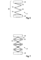
- Fig. 6 shows the third embodiment of the door actuator assembly 1.
- the same or functionally identical components are provided in all embodiments with the same reference numerals.
- Fig. 6 only a section is shown.
- two end pieces 28 are shown on both sides of the damper assembly 17 here.
- the remaining components of the Mitbetuschigeran Aunt correspond to the previous embodiments and are hidden.
- the damper assembly 17 is formed as a concertina-like spring 26.
- This concertina-like spring 26 is either integrally molded of plastic or bent from a sheet metal.
- the individual legs of the concertina-like spring 26 represent the juxtaposed damping elements 18.
- Fig. 7 shows the fourth embodiment of the door actuator assembly 1.
- the same or functionally identical components are provided in all embodiments with the same reference numerals. Relevant differences arise here only in the damper assembly 17. The remaining components of the door actuator assembly 1 are therefore hidden.
- shock elements 19 are arranged here between the damping elements 18.
- the shock elements 19 are arranged between the adjacent sliding wings 31, 32 of the damping elements 18.
- the middle portions 33 of the damping elements 18 encounter here again directly on each other, as in the Fig. 4 and 5 is shown.
- the damping elements 18 and the impact elements 19 are guided in the guide channels 12 as in the previous embodiments. As a result, a buckling of the damper assembly 17 is avoided even with a very large length.
Landscapes
- Power-Operated Mechanisms For Wings (AREA)
- Lock And Its Accessories (AREA)
- Support Devices For Sliding Doors (AREA)
Applications Claiming Priority (1)
| Application Number | Priority Date | Filing Date | Title |
|---|---|---|---|
| DE102012105114A DE102012105114A1 (de) | 2012-06-13 | 2012-06-13 | Türbetätigeranordnung |
Publications (2)
| Publication Number | Publication Date |
|---|---|
| EP2674559A2 true EP2674559A2 (fr) | 2013-12-18 |
| EP2674559A3 EP2674559A3 (fr) | 2016-08-24 |
Family
ID=48444038
Family Applications (1)
| Application Number | Title | Priority Date | Filing Date |
|---|---|---|---|
| EP13002574.5A Withdrawn EP2674559A3 (fr) | 2012-06-13 | 2013-05-16 | Agencement d'actionnement de porte |
Country Status (2)
| Country | Link |
|---|---|
| EP (1) | EP2674559A3 (fr) |
| DE (1) | DE102012105114A1 (fr) |
Cited By (4)
| Publication number | Priority date | Publication date | Assignee | Title |
|---|---|---|---|---|
| DE102014204179A1 (de) * | 2014-03-07 | 2015-09-10 | Geze Gmbh | Vorrichtung zur Begrenzung des Öffnungswinkels eines Flügels einer Tür oder eines Fensters |
| EP2754817A3 (fr) * | 2013-01-11 | 2018-01-03 | dormakaba Deutschland GmbH | Plaque de fixation |
| WO2020134583A1 (fr) * | 2018-12-26 | 2020-07-02 | 深圳市福隆智能科技发展有限公司 | Dispositif porte-fenêtre électrique invisible |
| WO2021009107A1 (fr) * | 2019-07-12 | 2021-01-21 | Maco Technologie Gmbh | Unité de rails de guidage pour un limiteur d'ouverture, limiteur d'ouverture comprenant une unité de rails de guidage de ce type, et ensemble formant battant comprenant un tel limiteur d'ouverture |
Family Cites Families (4)
| Publication number | Priority date | Publication date | Assignee | Title |
|---|---|---|---|---|
| US2289092A (en) * | 1940-09-25 | 1942-07-07 | American Hardware Corp | Door holder |
| DE2436299C2 (de) * | 1974-07-27 | 1989-04-06 | Wilh. Frank Gmbh, 7022 Leinfelden-Echterdingen | Vorrichtung zur Begrenzung des Öffnungswinkels eines Flügels eines Fensters, einer Tür o.dgl |
| DE3927817C5 (de) * | 1989-08-23 | 2009-09-10 | Geze Gmbh | Vorrichtung zur Öffnungsbegrenzung für eine Schwenktür |
| DE102008047748A1 (de) * | 2008-09-17 | 2010-04-15 | Automotive Group Ise Industries Hainichen Gmbh | Dämpfersystem zur Endlagendämpfung an Laderaumschiebetür |
-
2012
- 2012-06-13 DE DE102012105114A patent/DE102012105114A1/de not_active Withdrawn
-
2013
- 2013-05-16 EP EP13002574.5A patent/EP2674559A3/fr not_active Withdrawn
Non-Patent Citations (1)
| Title |
|---|
| None |
Cited By (5)
| Publication number | Priority date | Publication date | Assignee | Title |
|---|---|---|---|---|
| EP2754817A3 (fr) * | 2013-01-11 | 2018-01-03 | dormakaba Deutschland GmbH | Plaque de fixation |
| DE102014204179A1 (de) * | 2014-03-07 | 2015-09-10 | Geze Gmbh | Vorrichtung zur Begrenzung des Öffnungswinkels eines Flügels einer Tür oder eines Fensters |
| DE102014204179B4 (de) | 2014-03-07 | 2021-11-25 | Geze Gmbh | Vorrichtung zur Begrenzung des Öffnungswinkels eines Flügels einer Tür oder eines Fensters |
| WO2020134583A1 (fr) * | 2018-12-26 | 2020-07-02 | 深圳市福隆智能科技发展有限公司 | Dispositif porte-fenêtre électrique invisible |
| WO2021009107A1 (fr) * | 2019-07-12 | 2021-01-21 | Maco Technologie Gmbh | Unité de rails de guidage pour un limiteur d'ouverture, limiteur d'ouverture comprenant une unité de rails de guidage de ce type, et ensemble formant battant comprenant un tel limiteur d'ouverture |
Also Published As
| Publication number | Publication date |
|---|---|
| EP2674559A3 (fr) | 2016-08-24 |
| DE102012105114A1 (de) | 2013-12-19 |
Similar Documents
| Publication | Publication Date | Title |
|---|---|---|
| DE102014114207B4 (de) | Schlosszunge mit einem einen Führungsabschnitt aufweisenden Klemmelement | |
| EP2376732B1 (fr) | Ferrure pour porte coulissante à deux battants | |
| DE202018102144U1 (de) | Energieführungskette mit Dämpfungselementen sowie Seitenteil dafür | |
| EP2674559A2 (fr) | Agencement d'actionnement de porte | |
| EP2672042A2 (fr) | Agencement de rail de guidage | |
| EP1568833B1 (fr) | Gâche pour une fenêtre ou une porte | |
| DE102016111542B4 (de) | Schubkette mit standardisiertem Endstück | |
| EP3835525A1 (fr) | Ferrure de porte coulissante et agencement de porte coulissante associée | |
| DE102008003565A1 (de) | Abdeckelement für eine Gleitschiene | |
| DE102009007416A1 (de) | Dämpfungseinrichtung für Möbeltüren | |
| EP2674557A2 (fr) | Agencement d'actionnement de porte | |
| DE102008057397A1 (de) | Linearführung | |
| DE102014217711B4 (de) | Kulissenanordnung für eine Beschlagteilanordnung | |
| DE102012222210A1 (de) | Zur verdeckten Anordnung vorgesehenes Ecklager | |
| DE102013226720B4 (de) | Einstellbare Vertikalaussteifung mit Gleiter für einen abstellbaren Flügel eines Fensters einer Tür oder dergleichen | |
| EP2674558B1 (fr) | Agencement d'actionnement de porte | |
| DE2656543A1 (de) | Scharnierband-befestigung mit verstellbarem scharnierbandarm | |
| EP2617927A2 (fr) | Agencement de rail de guidage | |
| DE202018105183U1 (de) | Kollisionsdämpfer für Möbelteile | |
| AT280093B (de) | Einstellbares Scharnierband | |
| DE102005000189A1 (de) | Beschlagteil für einen Treibstangenbeschlag | |
| DE202008014424U1 (de) | Laufteil für eine Schiebetür | |
| DE202016106447U1 (de) | Vertikalträger für ein Aufbewahrungssystem und Aufbewahrungssystem mit wenigstens zwei solchen Vertikalträgern | |
| DE102014217715B4 (de) | Eckdichtanordnung für eine Beschlagteilanordnung | |
| DE202013001134U1 (de) | Scharniervorrichtung, insbesondere innenliegend anordenbare Scharniervorrichtung, vzw. 180°-Grad-Scharnier |
Legal Events
| Date | Code | Title | Description |
|---|---|---|---|
| PUAI | Public reference made under article 153(3) epc to a published international application that has entered the european phase |
Free format text: ORIGINAL CODE: 0009012 |
|
| AK | Designated contracting states |
Kind code of ref document: A2 Designated state(s): AL AT BE BG CH CY CZ DE DK EE ES FI FR GB GR HR HU IE IS IT LI LT LU LV MC MK MT NL NO PL PT RO RS SE SI SK SM TR |
|
| AX | Request for extension of the european patent |
Extension state: BA ME |
|
| RAP1 | Party data changed (applicant data changed or rights of an application transferred) |
Owner name: DORMA DEUTSCHLAND GMBH |
|
| PUAL | Search report despatched |
Free format text: ORIGINAL CODE: 0009013 |
|
| AK | Designated contracting states |
Kind code of ref document: A3 Designated state(s): AL AT BE BG CH CY CZ DE DK EE ES FI FR GB GR HR HU IE IS IT LI LT LU LV MC MK MT NL NO PL PT RO RS SE SI SK SM TR |
|
| AX | Request for extension of the european patent |
Extension state: BA ME |
|
| RIC1 | Information provided on ipc code assigned before grant |
Ipc: E05F 5/06 20060101ALI20160720BHEP Ipc: E05F 5/00 20060101ALI20160720BHEP Ipc: E05F 5/02 20060101ALI20160720BHEP Ipc: E05C 17/28 20060101ALN20160720BHEP Ipc: E05F 3/22 20060101AFI20160720BHEP |
|
| STAA | Information on the status of an ep patent application or granted ep patent |
Free format text: STATUS: REQUEST FOR EXAMINATION WAS MADE |
|
| 17P | Request for examination filed |
Effective date: 20170224 |
|
| RBV | Designated contracting states (corrected) |
Designated state(s): AL AT BE BG CH CY CZ DE DK EE ES FI FR GB GR HR HU IE IS IT LI LT LU LV MC MK MT NL NO PL PT RO RS SE SI SK SM TR |
|
| RAP1 | Party data changed (applicant data changed or rights of an application transferred) |
Owner name: DORMAKABA DEUTSCHLAND GMBH |
|
| STAA | Information on the status of an ep patent application or granted ep patent |
Free format text: STATUS: THE APPLICATION IS DEEMED TO BE WITHDRAWN |
|
| 18D | Application deemed to be withdrawn |
Effective date: 20170225 |