EP2674658A1 - Fluidkupplungselement und entsprechende Anordnung - Google Patents
Fluidkupplungselement und entsprechende Anordnung Download PDFInfo
- Publication number
- EP2674658A1 EP2674658A1 EP13172087.2A EP13172087A EP2674658A1 EP 2674658 A1 EP2674658 A1 EP 2674658A1 EP 13172087 A EP13172087 A EP 13172087A EP 2674658 A1 EP2674658 A1 EP 2674658A1
- Authority
- EP
- European Patent Office
- Prior art keywords
- locking
- ball
- actuating
- coupling
- fluidic connection
- Prior art date
- Legal status (The legal status is an assumption and is not a legal conclusion. Google has not performed a legal analysis and makes no representation as to the accuracy of the status listed.)
- Granted
Links
Images


Classifications
-
- F—MECHANICAL ENGINEERING; LIGHTING; HEATING; WEAPONS; BLASTING
- F16—ENGINEERING ELEMENTS AND UNITS; GENERAL MEASURES FOR PRODUCING AND MAINTAINING EFFECTIVE FUNCTIONING OF MACHINES OR INSTALLATIONS; THERMAL INSULATION IN GENERAL
- F16L—PIPES; JOINTS OR FITTINGS FOR PIPES; SUPPORTS FOR PIPES, CABLES OR PROTECTIVE TUBING; MEANS FOR THERMAL INSULATION IN GENERAL
- F16L21/00—Joints with sleeve or socket
- F16L21/08—Joints with sleeve or socket with additional locking means
-
- F—MECHANICAL ENGINEERING; LIGHTING; HEATING; WEAPONS; BLASTING
- F16—ENGINEERING ELEMENTS AND UNITS; GENERAL MEASURES FOR PRODUCING AND MAINTAINING EFFECTIVE FUNCTIONING OF MACHINES OR INSTALLATIONS; THERMAL INSULATION IN GENERAL
- F16L—PIPES; JOINTS OR FITTINGS FOR PIPES; SUPPORTS FOR PIPES, CABLES OR PROTECTIVE TUBING; MEANS FOR THERMAL INSULATION IN GENERAL
- F16L37/00—Couplings of the quick-acting type
- F16L37/22—Couplings of the quick-acting type in which the connection is maintained by means of balls, rollers or helical springs under radial pressure between the parts
- F16L37/23—Couplings of the quick-acting type in which the connection is maintained by means of balls, rollers or helical springs under radial pressure between the parts by means of balls
Definitions
- the present invention relates to a fluidic coupling element, of the type comprising: a base body defining a central axis (XX) for fitting a complementary fluidic coupling element, a locking ring, movable relative to the base body; at least one locking ball adapted to lock the complementary fluidic connection element relative to the base body, the or each locking ball being movable radially in the body between a locking position, in which the locking ball is adapted to locking the complementary fluidic connection element, and an unlocking position, in which the locking ball releases the passage for the complementary fluidic coupling element, at least one actuating ball of the locking ring adapted to be pushed into an elongate housing of the base body by the complementary fluidic coupling element during the coupling of the element connection and the complementary coupling element, for axially moving the locking ring from a locking position, wherein the or each locking ball is locked in said locking position, at least to a release position wherein the or each locking ball is free to move in said unlocking position of the biasing means of
- a coupling assembly comprising such a coupling element is known to DE3023377 .
- This document discloses a connection with actuating balls (in the lower part of the figures 1 and 2 of this document) housed in an elongated dwelling. These balls pushed by the complementary coupling element I move the locking ring so that the locking balls (in the upper part of the figures 1 and 2 of this document) can engage in element I for its locking. It is explicit that all the balls have the same diameter.
- EP2088360 discloses a coupling in which the locking ball also contributes to the displacement of the locking ring at the coupling and in which the angle ⁇ of the surface of the complementary coupling element 32a in contact with the actuating ball is greater than the angle ⁇ of the inclined surface 50a of the locking ring in contact with the actuating ball when the actuating ball moves the locking ring.
- the object of the invention is to solve at least one of these disadvantages and to propose a coupling element that allows reliable coupling, and this preferably with economical means.
- the subject of the invention is an element as defined above, characterized in that the or each actuating ball has a diameter ( D ) greater than the diameter ( d ) of the or each locking ball. .
- the invention also relates to a fluidic connection assembly comprising a fluidic connection element and a complementary fluidic connection element, characterized in that the fluidic coupling element is an element as described above.
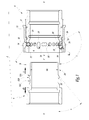
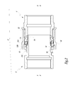
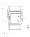
- FIG. 1 On the figure 1 is shown a fluid coupling assembly according to the invention, designated by the general reference 2.
- the fluidic connection assembly 2 comprises a fluidic connection element 4 and a complementary fluidic connection element 6.
- the fluidic connection element 4 comprises a base body 8 of revolution about a central axis XX of fitting with the fluidic coupling element complementary 6, a locking ring 10 and a spring 12.
- the expressions “axial” and “radial” will be used with respect to this axis XX.
- front and back will be used later with respect to the fluidic connection element 4 or the complementary fluidic connection element 6 to which the object designated by “front” or “back” is associated.
- Front designates the axial side of one of the fluidic connection elements 4 and complementary fluidic connection element 6 directed towards the other of the fluidic connection elements 4 and complementary fluidic connection element 6.
- Back refers to the axial side of one of the fluidic connection element 4 and complementary fluidic connection element 6 directed opposite the other of the fluidic connection elements 4 and complementary fluidic connection element 6.
- the "front” side of the fluidic connection element 4 is located to the left of the figure 1 and the “back” side of the fluidic coupling element 4 is located to the right of the figure 1 .
- the “front” and “back” sides of the complementary fluidic connection element 6 are located opposite.
- Each fluidic connection element 4 and complementary fluidic connection element 6 defines an "inside” side and an “outside” side, the inside being located radially closer to the central axis than the "outside” side.
- the fluid coupling assembly 2 defines a coupling direction S directed in the direction of insertion of the complementary fluidic connection element 6 into the fluidic coupling element 4.
- the fluidic coupling assembly 2 defines a direction of flow. SD disconnection directed in the direction of exit of the complementary fluidic connection element 6 out of the fluidic connection element 4.
- the rear of the base body 8 is connected to a not shown fluid pipe.
- the fluidic connection element 4 is furthermore provided with a plurality of locking members 14 able to lock the complementary fluidic connection element 6 with respect to the base body 8 when they are in their locking position.
- the locking ring 10 is a piece of revolution that surrounds the base body 8 and is movable relative to the base body 8 between different axial positions.
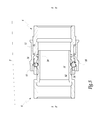
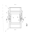
- These positions include, at least one locking position of the locking members ( Figures 1 and 2 ) in which the locking ring 10 is pushed by the spring 12, a release position of the locking members 14, and a contact position ( Figure 4 ). In the position of the so-called locking ring, the locking members 14 are blocked radially by the locking ring 10 in their locking position.
- the position of the so-called release locking ring 10 corresponds to the position of the foremost locking ring 10 in which the locking 14 are free to move radially in their unlocking position.
- the locking members 14 In their locking position, with the locking ring in the locked position, the locking members 14 protrude inwardly relative to the body 8 and oppose, when the coupling is coupled, to a withdrawal out of the element 4 of the complementary coupling element 6 or, when the coupling is not coupled, to a fitting in the connecting element 4 of the complementary coupling element 6.
- their unlocking position radially towards the external to their locking position with the balls 14 protruding outside the body 8, the locking members 14 no longer protrude inwardly relative to the body 8 and release the passage for the connecting element 6 in the connecting element 4. They do not then oppose a withdrawal from the connecting element 4 or a fitting in the connecting element 4 of the complementary coupling element 6.
- the fluidic connection element 4 also comprises at least one, and especially at least three, actuating member (s) 16 of the locking ring 10 adapted (s) to push the locking ring from its locking position at least to his position of liberation.
- each actuating member 16 is an organ of revolution and in particular a ball.
- each locking member 14 is an organ of revolution and in particular a ball.
- the or each actuating member 16 has a diameter D greater than the diameter d of the or each locking member 14, each diameter corresponding to the dimension of the member considered radially to the axis XX.
- all the actuating members 16 have the same diameter.
- all the locking members 14 have the same diameter.
- the diameter D of the or each actuating member 16 is between 105% and 125% of the diameter d of the or each locking member 14.
- the actuating members 16 come into contact with a rear end 20 of the elongated housing 18 (see below).
- the base body 8 comprises, for each actuating member 16, an elongate housing 18 extending parallel to the central axis XX, opening on either side of the base body 8 and whose width, perpendicular to the plane of the figures 1 and 2 , corresponds substantially to the transverse dimension of the actuating member 16.
- Each elongate housing 18 comprises a rear end 20 and a front end 22.
- the associated actuating member 16 is pushed against the rear end 20 when the 'coupling.
- the rear end 20 has a slope forming an angle ⁇ included between 105 ° and 130 ° with respect to the central axis XX and flaring towards the rear of the connecting element 4.
- the or each actuating member 16 protrudes from the base body 8 on both sides of an identical radial distance, a distance substantially equal to the radial internal extension of the locking ball relative to the base body 8.
- the release position of the locking ring is located axially between the locking position of the locking ring in the uncoupled state and the contact position of the locking ring.
- the locking ring 10 In the end-of-travel position and in the uncoupled state, the locking ring 10 is resiliently urged by the spring 12 against each actuating member 16 and each actuating member 16 abuts against the front end 22. this position, the locking ring 10 is in contact with each actuating member 16.
- the complementary fluidic connection element 6 is a piece of revolution about a central axis X'-X '.
- the central axis X'-X ' coincides with the central axis XX during fitting of the complementary coupling element 6 with the connecting element 4.
- the complementary coupling element 6 is connected to the rearward to a pipe not shown and comprises an actuating collar 32 adapted to be applied against the or each actuating member 16.
- the actuating collar 32 has an actuating slope 32A, facing the front of the Element 6.
- the actuating slope 32A is inclined at an angle ⁇ of 25 ° to 50 °, in this case 40 °, with respect to the central axis X'-X 'and flares towards the Rear of the complementary coupling element 6.
- the actuating flange 32 has an apex 32B behind and adjacent to the actuating slope 32A.
- the element 6 further comprises a groove 32C disposed at the rear of the actuating collar 32.
- the fluidic coupling element 4 further comprises a seal 24 disposed in an internal groove 26 formed in the body of base 8.
- the complementary fluidic connection element 6 comprises a sealing surface 28 adapted to cooperate with the seal 24 in the coupled state.
- the sealing surface 28 has an outer diameter DE.
- Each actuating member 16 and the associated housing 18 delimit an extreme radially inner position of this actuating member 16 relative to the base body 8. In this extreme radially inner position, each actuating member 16 is located radially at a distance from difference in the outer diameter DE of the sealing surface 28 during coupling.
- the base body 8 For each locking member 14, the base body 8 comprises a housing 30.
- the housing 30 is in this case mainly cylindrical with a circular section and guides the locking member 14 in its radial movement between its locking position and its position. unlocking.
- the housing 30 is disposed rearwardly relative to the front end 22 of the elongate housing 18 and forward relative to the rear end 22. The axial positions of the housings 18 and 30 thus overlap partially.
- Each locking member 14 and the associated housing 30 delimit an extreme radially inner position of this locking member 14 relative to the base body 8. In this extreme radially inner position, each locking member 14 is located radially away from the outer diameter DE of the sealing surface 28 during coupling.
- the rear end 20 of the elongated housing 18 is arranged axially rearward with respect to the housing 30.
- the locking ring 10 comprises a covering surface 33 and an actuating slope 34 against which the or each actuating member 16 is applied during the coupling.
- the actuating slope 34 being inclined at an angle ⁇ of 25 ° to 50 °, in this case 35 °, with respect to the central axis XX and flaring towards the front of the connecting element 4
- the angle ⁇ is greater than the second angle ⁇ , preferably at least 5 °, preferably at most 10 °.
- the assembly according to the invention operates in the following manner during the coupling.
- the explanations are given for a locking ball and an actuating ball, the behavior being similar for the other locking balls / locking members 14 and the other actuating balls / actuating members 16.
- the complementary coupling element 6 is inserted into the coupling element 4 by the operator in the direction S along the axis XX.
- the flange 32 engages in the base body 8 with reduced radial clearance and then the sealing surface 28 comes into contact with the seal 24, thereby creating the seal between the two connecting elements 6 and 4.
- the collar 32 comes into contact with the actuating ball 16.
- the actuating ball is then wedged in engagement between the complementary coupling element 6 and the locking ring 10 in the locked position, precisely between the actuating slope 32A inclined at an angle ⁇ of the actuating collar 32 and the actuating slope 34 of the ring 10 inclined by an angle ⁇ .
- the locking ring 10 reaches its release position (not shown) of the locking members 14, in which the locking members 14 have sufficient radial clearance with the locking ring 10 on the outside of the body 8 to be able to move in the unlocking position.
- the actuating ball 16 is not yet in contact with the rear end 20 of the elongated housing 18.
- the locking ring 10 continues to move against the spring 12, beyond the contact position.
- the vertex 32B axially passes the locking ball 14, and the locking ball can move radially inwards in the groove 32C in a locking position of the complementary coupling element 6 in the connecting element 4.
- the fact that the locking ball 14 is in contact with the vertex 32B in its unlocking position or radially opposite the groove 32C when the actuating ball 16 comes into contact with the vertex 32B ensures that the locking ring 10 can not be pushed into a position where it could lock the actuating ball 16 in the groove 32C behind the actuating flange 32 and where the locking ball 14 would not be in the locking position in the groove 32C of the complementary coupling element 6.
- the locking ball 14 has no action on the recoil of the locking ring.
- the coupling is automatic in the sense that the only action of fitting of the complementary coupling element 6 in fluidic coupling element 4 by the operator leads to the coupling of the two coupling elements 4, 6. locking does not have to be moved by further action.
- the locking ring 10 In the coupled position, the locking ring 10 is pushed in abutment against the actuating ball 16 which does not come into contact with the complementary coupling element 6.
- the position of the locking ring 10 in the coupled state is axially identical to its position in the uncoupled state of the coupling assembly. These two positions correspond to a locking position of the locking members 14 in their locking position.
- the uncoupling is carried out as follows.
- the locking ring 10 is moved rearwardly of the connecting member 4 to a stop, beyond the release position, and held in this position by the operator. This frees a radial clearance space of the locking ring 10 for the locking ball 14 and for the actuating ball 16 ( Figure 8 ).
- the difference in diameters also ensures more radial clearance for the locking balls with respect to the locking ring as soon as the complementary coupling element 6 comes into contact with the locking balls 14, which ensures that the Locking balls 14 have no action on the recoil of the locking ring 10 at the coupling and that the coupling forces are minimal.
- angle ⁇ The difference in inclination or angle between the operating slope 32A of the actuating collar 32 of the complementary coupling element 6 (angle ⁇ ) and the operating slope 34 of the locking ring 10 (angle ⁇ ) ensures that the ball or the actuating member 16 remains in engagement between the complementary coupling element 6 and the locking ring 10, without escaping radially outwardly in the movement of the actuating ball 16 in the elongate housing 18 until it comes into contact with the rear end 22 during coupling, preferably the angle difference is greater than 0 ° and less than 10 ° and is in particular equal to 5 It is necessary that the angle ⁇ is greater than or equal to the angle ⁇ .
- the slope of the rear end 20 of the housing 18 by an angle ⁇ makes it possible to drive the actuating ball 16 in a short axial coupling force.
- the angle ⁇ is preferably equal to 120 °, but may be between 105 ° and 130 °.
- the diameter DE of the sealing surface 28 of the complementary coupling element 6 is smaller than the minimum enveloping inner diameter on which the actuating balls are arranged and the minimum enveloping inside diameter on which the locking, preserves the sealing surface 28 of the contacts with the actuating balls and locking at the coupling and uncoupling.
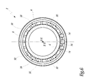
- At least 3 actuating members are provided, arranged regularly around the axis XX (every 120 °) to distribute the force exerted on the locking ring at the coupling, to limit the embrittlement of the body base 8 and accommodate a large number of locking balls (in this case 18 locking balls in the embodiment shown).
- the coupling assembly comprises a complementary coupling element 6 and / or a coupling element 4 equipped with a valve.
Landscapes
- Engineering & Computer Science (AREA)
- General Engineering & Computer Science (AREA)
- Mechanical Engineering (AREA)
- Quick-Acting Or Multi-Walled Pipe Joints (AREA)
- Clamps And Clips (AREA)
Applications Claiming Priority (1)
| Application Number | Priority Date | Filing Date | Title |
|---|---|---|---|
| FR1255596A FR2992048B1 (fr) | 2012-06-15 | 2012-06-15 | Element de raccord fluidique et ensemble correspondant |
Publications (2)
| Publication Number | Publication Date |
|---|---|
| EP2674658A1 true EP2674658A1 (de) | 2013-12-18 |
| EP2674658B1 EP2674658B1 (de) | 2014-12-24 |
Family
ID=46754664
Family Applications (1)
| Application Number | Title | Priority Date | Filing Date |
|---|---|---|---|
| EP13172087.2A Active EP2674658B1 (de) | 2012-06-15 | 2013-06-14 | Fluidkupplungselement und entsprechende Anordnung |
Country Status (5)
| Country | Link |
|---|---|
| US (1) | US9476528B2 (de) |
| EP (1) | EP2674658B1 (de) |
| CN (1) | CN103511776B (de) |
| ES (1) | ES2529499T3 (de) |
| FR (1) | FR2992048B1 (de) |
Cited By (2)
| Publication number | Priority date | Publication date | Assignee | Title |
|---|---|---|---|---|
| EP4491926A1 (de) | 2023-07-12 | 2025-01-15 | Staubli Faverges | Fluidanschlusselement und fluidanschluss dafür |
| US12474003B2 (en) * | 2022-02-10 | 2025-11-18 | Staubli Faverges | Female fluid connector element and fluid connector comprising such an element |
Families Citing this family (16)
| Publication number | Priority date | Publication date | Assignee | Title |
|---|---|---|---|---|
| US9752714B2 (en) * | 2014-03-28 | 2017-09-05 | Eldon James Corp. | Releasable valved coupler |
| CN105221880B (zh) * | 2015-09-30 | 2017-10-31 | 日丰企业集团有限公司 | 管材连接结构及分集水器 |
| FR3046209B1 (fr) * | 2015-12-23 | 2018-02-16 | Staubli Faverges | Element femelle de raccord rapide et raccord rapide comprenant un tel element femelle |
| US9909703B2 (en) * | 2015-12-31 | 2018-03-06 | Dixon Quick Coupling | Fluid coupling and method |
| JP6832119B2 (ja) * | 2016-10-12 | 2021-02-24 | 積水化学工業株式会社 | 管体の継手構造および管体の接合方法 |
| CN106764184B (zh) * | 2017-02-13 | 2019-01-29 | 戴璨遥 | 插入式管道连接锁紧组件 |
| JP6560299B2 (ja) * | 2017-06-05 | 2019-08-14 | 日東工器株式会社 | 雌型管継手部材 |
| CN107499150A (zh) * | 2017-07-20 | 2017-12-22 | 北自所制造业自动化工程研究中心(常州)有限公司 | 集装箱式充电站 |
| CN107906289A (zh) * | 2017-12-22 | 2018-04-13 | 新乡平原航空液压设备有限公司 | 接头组件及其母接头、公接头 |
| CN108591656A (zh) * | 2018-01-16 | 2018-09-28 | 珠海格力电器股份有限公司 | 连接管组件及包括其的空调器 |
| EP3948042B1 (de) | 2019-04-01 | 2025-01-08 | Swagelok Company | Push-to-connect-anschlussbaugruppen für leitungen und anordnungen |
| CN109973487A (zh) * | 2019-04-24 | 2019-07-05 | 杭州富阳优拓工具有限公司 | 一种快速接头 |
| US11460137B2 (en) | 2020-03-12 | 2022-10-04 | Parker-Hannifin Corporation | Fluid connection systems |
| US12510176B2 (en) | 2021-11-17 | 2025-12-30 | Swagelok Company | Check valve |
| WO2023091538A1 (en) | 2021-11-17 | 2023-05-25 | Swagelok Company | Check valve |
| FR3165054A1 (fr) | 2024-07-24 | 2026-01-30 | Staubli Faverges | Elément et ensemble de raccord fluidique |
Citations (2)
| Publication number | Priority date | Publication date | Assignee | Title |
|---|---|---|---|---|
| DE3023377A1 (de) * | 1980-06-23 | 1982-01-14 | Carl Kurt Walther Gmbh & Co Kg, 5600 Wuppertal | Schnellkupplung, insbesondere schnellverschlusskupplung |
| EP2088360A1 (de) * | 2006-11-24 | 2009-08-12 | Nitto Kohki Co., Ltd. | Verbindung und für die verbindung verwendet(r) buchse und stecker |
Family Cites Families (4)
| Publication number | Priority date | Publication date | Assignee | Title |
|---|---|---|---|---|
| US2473973A (en) * | 1945-05-21 | 1949-06-21 | Albert T Scheiwer | Coupling |
| JP2000266264A (ja) * | 1999-03-12 | 2000-09-26 | Yasusada Sakai | ガス放出防止装置 |
| JP3983728B2 (ja) * | 2003-09-18 | 2007-09-26 | 日東工器株式会社 | 管継手及び管継手のソケット |
| DE102008009616A1 (de) * | 2008-02-18 | 2009-08-20 | Walther & Walther Gmbh & Co. Kg | Aus Kupplungsteilen bestehende Kupplung |
-
2012
- 2012-06-15 FR FR1255596A patent/FR2992048B1/fr not_active Expired - Fee Related
-
2013
- 2013-06-11 US US13/914,816 patent/US9476528B2/en active Active
- 2013-06-14 EP EP13172087.2A patent/EP2674658B1/de active Active
- 2013-06-14 ES ES13172087.2T patent/ES2529499T3/es active Active
- 2013-06-17 CN CN201310239620.6A patent/CN103511776B/zh active Active
Patent Citations (2)
| Publication number | Priority date | Publication date | Assignee | Title |
|---|---|---|---|---|
| DE3023377A1 (de) * | 1980-06-23 | 1982-01-14 | Carl Kurt Walther Gmbh & Co Kg, 5600 Wuppertal | Schnellkupplung, insbesondere schnellverschlusskupplung |
| EP2088360A1 (de) * | 2006-11-24 | 2009-08-12 | Nitto Kohki Co., Ltd. | Verbindung und für die verbindung verwendet(r) buchse und stecker |
Cited By (4)
| Publication number | Priority date | Publication date | Assignee | Title |
|---|---|---|---|---|
| US12474003B2 (en) * | 2022-02-10 | 2025-11-18 | Staubli Faverges | Female fluid connector element and fluid connector comprising such an element |
| EP4491926A1 (de) | 2023-07-12 | 2025-01-15 | Staubli Faverges | Fluidanschlusselement und fluidanschluss dafür |
| FR3151071A1 (fr) | 2023-07-12 | 2025-01-17 | Staubli Faverges | Élément de raccord fluidique et raccord fluidique associé |
| US12516762B2 (en) | 2023-07-12 | 2026-01-06 | Staubli Faverges | Fluidic coupling element and associated fluidic coupling |
Also Published As
| Publication number | Publication date |
|---|---|
| FR2992048A1 (fr) | 2013-12-20 |
| CN103511776B (zh) | 2017-10-10 |
| US20130334814A1 (en) | 2013-12-19 |
| CN103511776A (zh) | 2014-01-15 |
| US9476528B2 (en) | 2016-10-25 |
| FR2992048B1 (fr) | 2014-07-25 |
| EP2674658B1 (de) | 2014-12-24 |
| ES2529499T3 (es) | 2015-02-20 |
Similar Documents
| Publication | Publication Date | Title |
|---|---|---|
| EP2674658B1 (de) | Fluidkupplungselement und entsprechende Anordnung | |
| EP2048425B1 (de) | Anschlussbuchse und eine solche Buchse umfassender Anschluss | |
| EP2141402B1 (de) | Anschlusselement mit Haken und Anschluss, der mindestens ein solches Element umfasst | |
| CA2947799C (fr) | Raccord tubulaire securise a connexion automatique | |
| EP2439440B1 (de) | Anschlussvorrichtung mit Verriegelung durch Gewindegriffe, und Anschluss, der eine solche Vorrichtung enthält | |
| EP1862720B1 (de) | Verbindungssteckerelement und Schnellverbindung, die ein solches Element beinhaltet | |
| EP2971920B1 (de) | Rohrverbindung mit automatischer verbindung | |
| FR2914980A1 (fr) | Element femelle de raccord et raccord comprenant un tel element femelle | |
| FR2820489A1 (fr) | Dispositif de branchement d'alimentation pour un systeme a pression de fluide | |
| FR2901595A1 (fr) | Element de raccord a rainure de verrouillage et raccord incorporant un tel element | |
| WO2008074933A1 (fr) | Connecteur rapide | |
| EP3301341B1 (de) | Anschluss und hydraulischer bremsschaltkreis für rad, das einen solchen anschluss integriert hat | |
| FR2843624A1 (fr) | Dispositif de branchement d'alimentation pour un systeme a pression de fluide | |
| EP1422461A1 (de) | Schnellkupplung zur trennbaren Verbindung von zwei Rohre | |
| EP3184870B1 (de) | Buchse eines schnellanschlusses, und eine solche buchse umfassender schnellanschluss | |
| EP2778495A1 (de) | Aufnahmeelement und Anschlussstück zur Ausführung einer abnehmbaren Verbindung zwischen zwei Flüssigkeitskanalisationssystemen | |
| FR3100305A1 (fr) | Dispositif de raccordement, notamment pour la réalisation de circuit de circulation de fluide | |
| EP4571164A1 (de) | Fluidverbindungsvorrichtung und fluidverbindungsanordnung mit solch einer fluidverbindungsvorrichtung | |
| FR2836203A1 (fr) | Raccord destine a relier des conduites hydrauliques | |
| EP4361486B1 (de) | Fluidverbinder und verfahren zur montage davon | |
| EP0742403A1 (de) | Fluiddichtkupplung | |
| FR2910109A1 (fr) | Raccord rapide de canalisation. | |
| EP3862610B1 (de) | Fluidkupplung | |
| EP3798490B1 (de) | Fluidanschlusselement | |
| EP0533537B1 (de) | Ausrücklager für eine gezogene Kupplung, insbesondere für Kraftfahrzeuge |
Legal Events
| Date | Code | Title | Description |
|---|---|---|---|
| PUAI | Public reference made under article 153(3) epc to a published international application that has entered the european phase |
Free format text: ORIGINAL CODE: 0009012 |
|
| AK | Designated contracting states |
Kind code of ref document: A1 Designated state(s): AL AT BE BG CH CY CZ DE DK EE ES FI FR GB GR HR HU IE IS IT LI LT LU LV MC MK MT NL NO PL PT RO RS SE SI SK SM TR |
|
| AX | Request for extension of the european patent |
Extension state: BA ME |
|
| 17P | Request for examination filed |
Effective date: 20140520 |
|
| RBV | Designated contracting states (corrected) |
Designated state(s): AL AT BE BG CH CY CZ DE DK EE ES FI FR GB GR HR HU IE IS IT LI LT LU LV MC MK MT NL NO PL PT RO RS SE SI SK SM TR |
|
| RIC1 | Information provided on ipc code assigned before grant |
Ipc: F16L 37/23 20060101AFI20140606BHEP |
|
| GRAP | Despatch of communication of intention to grant a patent |
Free format text: ORIGINAL CODE: EPIDOSNIGR1 |
|
| INTG | Intention to grant announced |
Effective date: 20140724 |
|
| GRAS | Grant fee paid |
Free format text: ORIGINAL CODE: EPIDOSNIGR3 |
|
| GRAA | (expected) grant |
Free format text: ORIGINAL CODE: 0009210 |
|
| AK | Designated contracting states |
Kind code of ref document: B1 Designated state(s): AL AT BE BG CH CY CZ DE DK EE ES FI FR GB GR HR HU IE IS IT LI LT LU LV MC MK MT NL NO PL PT RO RS SE SI SK SM TR |
|
| REG | Reference to a national code |
Ref country code: GB Ref legal event code: FG4D Free format text: NOT ENGLISH |
|
| REG | Reference to a national code |
Ref country code: CH Ref legal event code: EP |
|
| REG | Reference to a national code |
Ref country code: IE Ref legal event code: FG4D Free format text: LANGUAGE OF EP DOCUMENT: FRENCH |
|
| REG | Reference to a national code |
Ref country code: AT Ref legal event code: REF Ref document number: 703345 Country of ref document: AT Kind code of ref document: T Effective date: 20150115 |
|
| REG | Reference to a national code |
Ref country code: SE Ref legal event code: TRGR |
|
| REG | Reference to a national code |
Ref country code: DE Ref legal event code: R096 Ref document number: 602013000694 Country of ref document: DE Effective date: 20150219 |
|
| REG | Reference to a national code |
Ref country code: ES Ref legal event code: FG2A Ref document number: 2529499 Country of ref document: ES Kind code of ref document: T3 Effective date: 20150220 |
|
| REG | Reference to a national code |
Ref country code: NL Ref legal event code: T3 |
|
| PG25 | Lapsed in a contracting state [announced via postgrant information from national office to epo] |
Ref country code: NO Free format text: LAPSE BECAUSE OF FAILURE TO SUBMIT A TRANSLATION OF THE DESCRIPTION OR TO PAY THE FEE WITHIN THE PRESCRIBED TIME-LIMIT Effective date: 20150324 Ref country code: LT Free format text: LAPSE BECAUSE OF FAILURE TO SUBMIT A TRANSLATION OF THE DESCRIPTION OR TO PAY THE FEE WITHIN THE PRESCRIBED TIME-LIMIT Effective date: 20141224 Ref country code: FI Free format text: LAPSE BECAUSE OF FAILURE TO SUBMIT A TRANSLATION OF THE DESCRIPTION OR TO PAY THE FEE WITHIN THE PRESCRIBED TIME-LIMIT Effective date: 20141224 |
|
| REG | Reference to a national code |
Ref country code: LT Ref legal event code: MG4D |
|
| PG25 | Lapsed in a contracting state [announced via postgrant information from national office to epo] |
Ref country code: HR Free format text: LAPSE BECAUSE OF FAILURE TO SUBMIT A TRANSLATION OF THE DESCRIPTION OR TO PAY THE FEE WITHIN THE PRESCRIBED TIME-LIMIT Effective date: 20141224 Ref country code: LV Free format text: LAPSE BECAUSE OF FAILURE TO SUBMIT A TRANSLATION OF THE DESCRIPTION OR TO PAY THE FEE WITHIN THE PRESCRIBED TIME-LIMIT Effective date: 20141224 Ref country code: GR Free format text: LAPSE BECAUSE OF FAILURE TO SUBMIT A TRANSLATION OF THE DESCRIPTION OR TO PAY THE FEE WITHIN THE PRESCRIBED TIME-LIMIT Effective date: 20150325 Ref country code: RS Free format text: LAPSE BECAUSE OF FAILURE TO SUBMIT A TRANSLATION OF THE DESCRIPTION OR TO PAY THE FEE WITHIN THE PRESCRIBED TIME-LIMIT Effective date: 20141224 |
|
| REG | Reference to a national code |
Ref country code: AT Ref legal event code: MK05 Ref document number: 703345 Country of ref document: AT Kind code of ref document: T Effective date: 20141224 |
|
| REG | Reference to a national code |
Ref country code: FR Ref legal event code: PLFP Year of fee payment: 3 |
|
| PG25 | Lapsed in a contracting state [announced via postgrant information from national office to epo] |
Ref country code: EE Free format text: LAPSE BECAUSE OF FAILURE TO SUBMIT A TRANSLATION OF THE DESCRIPTION OR TO PAY THE FEE WITHIN THE PRESCRIBED TIME-LIMIT Effective date: 20141224 Ref country code: SK Free format text: LAPSE BECAUSE OF FAILURE TO SUBMIT A TRANSLATION OF THE DESCRIPTION OR TO PAY THE FEE WITHIN THE PRESCRIBED TIME-LIMIT Effective date: 20141224 Ref country code: RO Free format text: LAPSE BECAUSE OF FAILURE TO SUBMIT A TRANSLATION OF THE DESCRIPTION OR TO PAY THE FEE WITHIN THE PRESCRIBED TIME-LIMIT Effective date: 20141224 Ref country code: CZ Free format text: LAPSE BECAUSE OF FAILURE TO SUBMIT A TRANSLATION OF THE DESCRIPTION OR TO PAY THE FEE WITHIN THE PRESCRIBED TIME-LIMIT Effective date: 20141224 |
|
| PG25 | Lapsed in a contracting state [announced via postgrant information from national office to epo] |
Ref country code: AT Free format text: LAPSE BECAUSE OF FAILURE TO SUBMIT A TRANSLATION OF THE DESCRIPTION OR TO PAY THE FEE WITHIN THE PRESCRIBED TIME-LIMIT Effective date: 20141224 Ref country code: IS Free format text: LAPSE BECAUSE OF FAILURE TO SUBMIT A TRANSLATION OF THE DESCRIPTION OR TO PAY THE FEE WITHIN THE PRESCRIBED TIME-LIMIT Effective date: 20150424 Ref country code: PL Free format text: LAPSE BECAUSE OF FAILURE TO SUBMIT A TRANSLATION OF THE DESCRIPTION OR TO PAY THE FEE WITHIN THE PRESCRIBED TIME-LIMIT Effective date: 20141224 |
|
| REG | Reference to a national code |
Ref country code: DE Ref legal event code: R097 Ref document number: 602013000694 Country of ref document: DE |
|
| PG25 | Lapsed in a contracting state [announced via postgrant information from national office to epo] |
Ref country code: DK Free format text: LAPSE BECAUSE OF FAILURE TO SUBMIT A TRANSLATION OF THE DESCRIPTION OR TO PAY THE FEE WITHIN THE PRESCRIBED TIME-LIMIT Effective date: 20141224 |
|
| PLBE | No opposition filed within time limit |
Free format text: ORIGINAL CODE: 0009261 |
|
| STAA | Information on the status of an ep patent application or granted ep patent |
Free format text: STATUS: NO OPPOSITION FILED WITHIN TIME LIMIT |
|
| 26N | No opposition filed |
Effective date: 20150925 |
|
| PG25 | Lapsed in a contracting state [announced via postgrant information from national office to epo] |
Ref country code: MC Free format text: LAPSE BECAUSE OF FAILURE TO SUBMIT A TRANSLATION OF THE DESCRIPTION OR TO PAY THE FEE WITHIN THE PRESCRIBED TIME-LIMIT Effective date: 20141224 |
|
| PG25 | Lapsed in a contracting state [announced via postgrant information from national office to epo] |
Ref country code: SI Free format text: LAPSE BECAUSE OF FAILURE TO SUBMIT A TRANSLATION OF THE DESCRIPTION OR TO PAY THE FEE WITHIN THE PRESCRIBED TIME-LIMIT Effective date: 20141224 Ref country code: LU Free format text: LAPSE BECAUSE OF FAILURE TO SUBMIT A TRANSLATION OF THE DESCRIPTION OR TO PAY THE FEE WITHIN THE PRESCRIBED TIME-LIMIT Effective date: 20150614 |
|
| REG | Reference to a national code |
Ref country code: IE Ref legal event code: MM4A |
|
| PG25 | Lapsed in a contracting state [announced via postgrant information from national office to epo] |
Ref country code: IE Free format text: LAPSE BECAUSE OF NON-PAYMENT OF DUE FEES Effective date: 20150614 |
|
| REG | Reference to a national code |
Ref country code: FR Ref legal event code: PLFP Year of fee payment: 4 |
|
| PG25 | Lapsed in a contracting state [announced via postgrant information from national office to epo] |
Ref country code: MT Free format text: LAPSE BECAUSE OF FAILURE TO SUBMIT A TRANSLATION OF THE DESCRIPTION OR TO PAY THE FEE WITHIN THE PRESCRIBED TIME-LIMIT Effective date: 20141224 |
|
| PG25 | Lapsed in a contracting state [announced via postgrant information from national office to epo] |
Ref country code: HU Free format text: LAPSE BECAUSE OF FAILURE TO SUBMIT A TRANSLATION OF THE DESCRIPTION OR TO PAY THE FEE WITHIN THE PRESCRIBED TIME-LIMIT; INVALID AB INITIO Effective date: 20130614 Ref country code: BG Free format text: LAPSE BECAUSE OF FAILURE TO SUBMIT A TRANSLATION OF THE DESCRIPTION OR TO PAY THE FEE WITHIN THE PRESCRIBED TIME-LIMIT Effective date: 20141224 |
|
| REG | Reference to a national code |
Ref country code: FR Ref legal event code: PLFP Year of fee payment: 5 |
|
| PG25 | Lapsed in a contracting state [announced via postgrant information from national office to epo] |
Ref country code: CY Free format text: LAPSE BECAUSE OF FAILURE TO SUBMIT A TRANSLATION OF THE DESCRIPTION OR TO PAY THE FEE WITHIN THE PRESCRIBED TIME-LIMIT Effective date: 20141224 |
|
| PG25 | Lapsed in a contracting state [announced via postgrant information from national office to epo] |
Ref country code: BE Free format text: LAPSE BECAUSE OF NON-PAYMENT OF DUE FEES Effective date: 20150630 |
|
| PG25 | Lapsed in a contracting state [announced via postgrant information from national office to epo] |
Ref country code: SM Free format text: LAPSE BECAUSE OF FAILURE TO SUBMIT A TRANSLATION OF THE DESCRIPTION OR TO PAY THE FEE WITHIN THE PRESCRIBED TIME-LIMIT Effective date: 20141224 |
|
| REG | Reference to a national code |
Ref country code: FR Ref legal event code: PLFP Year of fee payment: 6 |
|
| PG25 | Lapsed in a contracting state [announced via postgrant information from national office to epo] |
Ref country code: MK Free format text: LAPSE BECAUSE OF FAILURE TO SUBMIT A TRANSLATION OF THE DESCRIPTION OR TO PAY THE FEE WITHIN THE PRESCRIBED TIME-LIMIT Effective date: 20141224 |
|
| PG25 | Lapsed in a contracting state [announced via postgrant information from national office to epo] |
Ref country code: PT Free format text: LAPSE BECAUSE OF FAILURE TO SUBMIT A TRANSLATION OF THE DESCRIPTION OR TO PAY THE FEE WITHIN THE PRESCRIBED TIME-LIMIT Effective date: 20141224 |
|
| PG25 | Lapsed in a contracting state [announced via postgrant information from national office to epo] |
Ref country code: AL Free format text: LAPSE BECAUSE OF FAILURE TO SUBMIT A TRANSLATION OF THE DESCRIPTION OR TO PAY THE FEE WITHIN THE PRESCRIBED TIME-LIMIT Effective date: 20141224 |
|
| P01 | Opt-out of the competence of the unified patent court (upc) registered |
Effective date: 20230509 |
|
| PGFP | Annual fee paid to national office [announced via postgrant information from national office to epo] |
Ref country code: DE Payment date: 20250627 Year of fee payment: 13 |
|
| PGFP | Annual fee paid to national office [announced via postgrant information from national office to epo] |
Ref country code: GB Payment date: 20250627 Year of fee payment: 13 |
|
| PGFP | Annual fee paid to national office [announced via postgrant information from national office to epo] |
Ref country code: NL Payment date: 20250626 Year of fee payment: 13 |
|
| PGFP | Annual fee paid to national office [announced via postgrant information from national office to epo] |
Ref country code: FR Payment date: 20250625 Year of fee payment: 13 |
|
| PGFP | Annual fee paid to national office [announced via postgrant information from national office to epo] |
Ref country code: TR Payment date: 20250526 Year of fee payment: 13 |
|
| PGFP | Annual fee paid to national office [announced via postgrant information from national office to epo] |
Ref country code: SE Payment date: 20250627 Year of fee payment: 13 |
|
| PGFP | Annual fee paid to national office [announced via postgrant information from national office to epo] |
Ref country code: ES Payment date: 20250701 Year of fee payment: 13 |
|
| PGFP | Annual fee paid to national office [announced via postgrant information from national office to epo] |
Ref country code: IT Payment date: 20250619 Year of fee payment: 13 |
|
| PGFP | Annual fee paid to national office [announced via postgrant information from national office to epo] |
Ref country code: CH Payment date: 20250701 Year of fee payment: 13 |