EP4491926A1 - Fluidanschlusselement und fluidanschluss dafür - Google Patents
Fluidanschlusselement und fluidanschluss dafür Download PDFInfo
- Publication number
- EP4491926A1 EP4491926A1 EP24188426.1A EP24188426A EP4491926A1 EP 4491926 A1 EP4491926 A1 EP 4491926A1 EP 24188426 A EP24188426 A EP 24188426A EP 4491926 A1 EP4491926 A1 EP 4491926A1
- Authority
- EP
- European Patent Office
- Prior art keywords
- fluid connection
- locking
- connection element
- distal
- proximal
- Prior art date
- Legal status (The legal status is an assumption and is not a legal conclusion. Google has not performed a legal analysis and makes no representation as to the accuracy of the status listed.)
- Granted
Links
Images








Classifications
-
- F—MECHANICAL ENGINEERING; LIGHTING; HEATING; WEAPONS; BLASTING
- F16—ENGINEERING ELEMENTS AND UNITS; GENERAL MEASURES FOR PRODUCING AND MAINTAINING EFFECTIVE FUNCTIONING OF MACHINES OR INSTALLATIONS; THERMAL INSULATION IN GENERAL
- F16L—PIPES; JOINTS OR FITTINGS FOR PIPES; SUPPORTS FOR PIPES, CABLES OR PROTECTIVE TUBING; MEANS FOR THERMAL INSULATION IN GENERAL
- F16L37/00—Couplings of the quick-acting type
- F16L37/28—Couplings of the quick-acting type with fluid cut-off means
- F16L37/30—Couplings of the quick-acting type with fluid cut-off means with fluid cut-off means in each of two pipe-end fittings
- F16L37/367—Couplings of the quick-acting type with fluid cut-off means with fluid cut-off means in each of two pipe-end fittings with two gate valves or sliding valves
-
- F—MECHANICAL ENGINEERING; LIGHTING; HEATING; WEAPONS; BLASTING
- F16—ENGINEERING ELEMENTS AND UNITS; GENERAL MEASURES FOR PRODUCING AND MAINTAINING EFFECTIVE FUNCTIONING OF MACHINES OR INSTALLATIONS; THERMAL INSULATION IN GENERAL
- F16L—PIPES; JOINTS OR FITTINGS FOR PIPES; SUPPORTS FOR PIPES, CABLES OR PROTECTIVE TUBING; MEANS FOR THERMAL INSULATION IN GENERAL
- F16L37/00—Couplings of the quick-acting type
- F16L37/22—Couplings of the quick-acting type in which the connection is maintained by means of balls, rollers or helical springs under radial pressure between the parts
- F16L37/23—Couplings of the quick-acting type in which the connection is maintained by means of balls, rollers or helical springs under radial pressure between the parts by means of balls
-
- F—MECHANICAL ENGINEERING; LIGHTING; HEATING; WEAPONS; BLASTING
- F16—ENGINEERING ELEMENTS AND UNITS; GENERAL MEASURES FOR PRODUCING AND MAINTAINING EFFECTIVE FUNCTIONING OF MACHINES OR INSTALLATIONS; THERMAL INSULATION IN GENERAL
- F16L—PIPES; JOINTS OR FITTINGS FOR PIPES; SUPPORTS FOR PIPES, CABLES OR PROTECTIVE TUBING; MEANS FOR THERMAL INSULATION IN GENERAL
- F16L37/00—Couplings of the quick-acting type
- F16L37/28—Couplings of the quick-acting type with fluid cut-off means
- F16L37/30—Couplings of the quick-acting type with fluid cut-off means with fluid cut-off means in each of two pipe-end fittings
- F16L37/32—Couplings of the quick-acting type with fluid cut-off means with fluid cut-off means in each of two pipe-end fittings at least one of two lift valves being opened automatically when the coupling is applied
- F16L37/34—Couplings of the quick-acting type with fluid cut-off means with fluid cut-off means in each of two pipe-end fittings at least one of two lift valves being opened automatically when the coupling is applied at least one of the lift valves being of the sleeve type, i.e. a sleeve being telescoped over an inner cylindrical wall
Definitions
- the present invention relates to a fluid connection element, configured to be assembled to a complementary tip, and to a fluid connection comprising such a connection element and a complementary tip.
- Fluid connectors are fluid connection devices comprising a fluid connector element and an associated mating end piece, which respectively form a female element and a male element of the fluid connector.
- Each of the fluid connector element and end piece comprises an internal passage, the respective internal passages being in fluid communication when the connector is in a mated configuration.
- the fluid connector element comprises a locking device, which can automatically engage when the mating end piece is engaged with the connector element, so as to maintain the connector in a mated configuration.
- a release device typically a ring, is provided to release the locking device and allow the fluid connector element and the mating end piece to be uncoupled.
- fluid connections In general, it is preferable to have fluid connections as compact as possible.
- the fluid connection element is sealed when the fluid connection is in the uncoupled configuration, for example by means of a sealing device.
- EP-2 674 658-A1 describes, for example, a fluid connection comprising a locking ring moved at the coupling by actuating balls of diameter greater than the diameter of the locking balls.
- the fluid connection element is only partially described, no details are given as to the structure of the body and no closing device is present.
- DE 302 3377-A1 describes, for its part, an automatic fluid connection with a fluid connection element comprising a body providing elongated housings 17, provided to receive actuating balls 17'.
- the actuating balls 17' are then held in place by a locking ring, which cooperates with a plug 18 and an elastic ring 19, the locking ring, the plug and the elastic ring being mounted from the front of the fluid connection element.
- the plug and the elastic ring are exposed to shocks and risk being damaged prematurely.
- such a structure requires the fluid connection element to be extended forwards, so as to leave sufficient radial space for the plug 18, which makes it a not very compact solution.
- this plug constitutes an additional part. No sealing device is described.
- US-4 949 745-A describes, for its part, a connecting element formed of several elements stacked on top of each other and held in position by an elastic ring and washers.
- the invention aims to address more specifically by proposing a rapid fluid connection which is both watertight in the uncoupled configuration, compact and simple.
- the assembly of the two proximal and distal parts of the body is carried out by means of an elastically deformable segment/obstacle, and the body of the connection element, and by extension the fluid connection, is radially compact, in particular more compact than if the proximal and distal parts were screwed together.
- the elastic obstacle housed partially in the external groove of the distal part and partially in the internal groove of the proximal part, is protected from external impacts, the connection element and the associated fluid connection thus being more durable.
- the piston and the valve ensure the sealing of the fluid connection element in the uncoupled configuration.
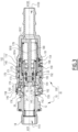
- a fluid connection R1 in accordance with a first embodiment, is described with reference to Figures 1 to 7 .
- the fluidic connection R1 comprises a fluidic connection element 100, located on the right of the insert a), and a complementary end piece 10, located on the left of the insert a).
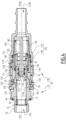
- the fluidic connection element 100 also called female element, is configured to be coupled to the complementary end piece 10, also called male element, according to a coupling sequence of the fluidic connection R1 described with reference to Figures 2 to 4 .
- the fluidic connector R1 is in a mated configuration, as shown in the figure 4 .
- the fluid connection element 100 comprises a front side, which is oriented towards the complementary tip 10 at the start of the coupling, and a rear side located opposite the front side.
- the front side of the fluid connection element 100 is also a distal side of this fluid connection element 100, while the rear side is a proximal side of this fluid connection element 100.
- a front surface of the fluid connection element 100 faces the front side, while a rear surface of the fluid connection element 100 faces the rear side.
- the complementary tip 10 comprises a front side, which is oriented towards the fluid connection element 100 at the beginning of the coupling, and a rear side located opposite the front side.
- the front side of the complementary tip 10 is also a distal side of the complementary tip 10, while the rear side is a proximal side of the complementary tip 10.
- the complementary end piece 10 generally has a shape of revolution around a main axis A10. Unless otherwise stated, in the remainder of the description the concepts of “radial” or “axial” for a surface belonging to the complementary end piece 10 are in reference to the main axis A10.
- a surface called “axial” with respect to a given axis is a surface whose normal at all points is parallel to this axis.
- an axial surface is a flat surface, which is geometrically carried by a plane orthogonal to this axis.
- a radial surface is a surface whose normal at all points is radial to this axis, in other words a cylindrical surface of circular section centered on this axis.
- the complementary tip 10 comprises a male body 12 of tubular shape, which delimits an internal channel V10 extending along the main axis A10.
- the internal channel V10 opens on the front side through a mouth 14, which is on the figure 1 closed by a movable valve 16.
- the main axis A10 defines an internal side of the complementary end piece 10.
- the male body 12 comprises a rear end 18, where the internal channel V10 opens.
- the rear end 18 can be connected to a pipe.
- the male body 12 comprises, on an external side of the male body 12 and from front to rear, a front end axial surface 20, which extends in a plane orthogonal to the main axis A10, a first substantially cylindrical portion which has an external radial end surface 22, an actuating collar 24, which extends in projection relative to the external radial end surface 22, an external locking groove 26, a second collar 28, and finally the rear end 18.
- the external locking groove 26 has a bottom surface 26A, which is here of cylindrical shape with circular section centered on the main axis A10.
- the external locking groove 26 is delimited by the actuating collar 24 on the front - or distal - side of the bottom surface 26A, and by the second collar 28 on the rear - or proximal - side of the bottom surface 26A.
- the actuating collar 24 here comprises, from front to rear, a truncated cone-shaped front surface 25A, which is centered on the main axis A10 and which diverges towards the rear. of the male body 12, a cylindrical intermediate surface 25B centered on the main axis A10, a truncated external portion 25C, which is centered on the main axis A10 and which converges towards the rear of the male body 12, and an internal axial portion 25D, which has the shape of a ring located in a plane orthogonal to the main axis A10.
- the truncated external portion 25C and the internal axial portion 25D together form a proximal wall 25E of the actuating collar 24.
- the proximal wall 25E thus delimits, on the distal side, the external locking groove 26.
- the second collar 28 here has a rear face 30A, which extends radially to the main axis A10 and which is arranged around the rear termination 18.
- a front groove 32 is formed in a hollow in the rear face 30A, the front groove 32 receiving a seal 34 for the sealed mounting of the rear termination 18 on the support.
- the second collar 28 has, on the front side, a proximal wall 36, which is here inclined and which delimits the external locking groove 26 on the proximal side.
- the complementary end piece 10 also comprises an internal ring 40, a circlip 42 and a spring 44.
- the internal ring 40 is mounted in the internal channel V10 of the male body 12 and is blocked, at the rear in the male body 12, by the circlip 42.
- the spring 44 is interposed between the valve 16 and the internal ring 40, so as to push the internal ring 40 towards the rear in abutment against the circlip 42, and to push the valve 16 towards the front of the complementary end piece 10.
- the valve 16 is pushed forward into abutment against a narrowed section of the mouth 14, the valve 16 being in a closed position.
- the valve 16 is received in the internal channel V10 and is movable in translation relative to the male body 12 along the main axis A10 between the closed position, in which the valve 16 seals the internal channel V10 and a retracted opening position.
- the complementary end piece 10 advantageously comprises a sealing gasket 17A, which is received in a radial groove formed in the valve 16. The sealing gasket 17A is thus interposed radially between the male body 12 and the valve 16 in the closed position.
- valve 16 in the closed position of the internal channel V10, the valve 16 is in front abutment against the male body 12 and cooperates in a sealed manner with the male body 12.
- the valve 16 is pushed back towards the rear of the male body 12 against the spring 44 and the passage of the fluid in the internal channel V10 is no longer prevented, the valve 16 is in the so-called retracted opening position.
- a front end axial surface 16A of the valve 16 and the front end axial surface 20 of the male body 12 are aligned, that is to say are substantially geometrically carried by the same plane, which is here orthogonal to the main axis A10.
- the complementary tip 10 complies with the specifications known as UQD, an acronym for “ Universal Quick Disconnect” - or “universal quick disconnect” in French -, established by the company Intel Corporation.
- the fluid connection element 100 is now described.
- the fluid connection element 100 generally has a shape of revolution around a central axis A100. Unless otherwise stated, in the remainder of the description, for a surface belonging to the fluid connection element 100, the concepts of “radial”, “axial” or “longitudinal” are made with reference to the central axis A100.
- the central axis A100 is thus a longitudinal axis of the fluid connection element 100.
- a direction or an “internal side” of the fluid connection element 100 is turned towards the central axis A100, the concepts of “external”, “towards the outside” being made with reference to a radial direction moving away from the central axis A100.
- the fluid connection element 100 comprises a body 102, which delimits an internal conduit V100, the internal conduit V100 of the fluid connection element 100 extending along the central axis A100 being configured to receive the complementary tip 10 via a front mouth 104 of the body 102.
- the internal conduit V100 is also a volume for receiving the complementary tip 10.
- the body 102 is also called a “female body”.
- the body 102 here comprises two parts, which are assembled to each other.
- the body 102 thus comprises a proximal part 110, which delimits a proximal portion of the internal conduit V100 and which has a rear termination 112, which is here intended to be connected to a pipe C1.
- the pipe C1 is not part of the fluid connection R1 but serves to specify the context of use thereof.
- the proximal part 110 is a single piece, in other words is made from a single piece.
- the body 102 also comprises a distal portion 140, which is in one piece and which delimits a distal portion of the internal conduit V100, the distal portion opening out at the front via the front mouthpiece 104 for receiving the complementary tip 10.
- a front portion of the body 02 is formed exclusively by the distal portion 140 while a rear portion of the body 102 is formed exclusively by the proximal portion 110, the proximal portion of the distal portion 140 and the distal portion of the proximal portion 110 being in radial overlap for the assembly of the proximal 110 and distal 140 portions.
- the proximal portion 110 is configured to be assembled to the distal portion 140 by fitting the distal portion 140 with the proximal portion 110, in particular in the proximal portion 110, in an assembled configuration of the body 102, the assembly of the proximal portion 110 to the distal portion 140 being locked by an elastically deformable obstacle.
- the obstacle is a split ring 190, shown in figure 1c ).
- split ring it is meant that the ring comprises a slot which passes through the ring over its entire radial thickness and over its entire length, the split ring therefore being discontinuous around the axis X100 when the body 102 is in the assembled configuration.
- the proximal portion 110 has a front end axial surface 114, which here has a ring shape and extends in a plane orthogonal to the central axis A100.
- the proximal portion 110 comprises an inner surface which is oriented towards the central axis A100 and which extends from the front end axial surface 114.
- the inner surface of the proximal portion 110 comprises, from front to rear, a first inner radial surface 121, a second inner radial surface 122, a third inner radial surface 123 and a fourth inner radial surface 124.
- the first, second, third and fourth internal radial surfaces 121 to 124 are connected two by two by chamfers and/or axial surfaces, that is to say surfaces parallel to a plane orthogonal to the central axis A100.
- the fourth internal radial surface 124 is here provided at the level of the rear end 112 of the proximal part 110.
- Each of the first, second, third and fourth internal radial surfaces 121 to 124 is cylindrical with a circular section centered on the central axis A100.
- the second internal radial surface 122 is located behind the first internal radial surface 121 and has an internal diameter smaller than the diameter of the first internal radial surface 121.
- the third internal radial surface 123 is located behind the second internal radial surface 122 and has an internal diameter smaller than the diameter of the second internal radial surface 122.
- the fourth internal radial surface 124 is located behind the third internal radial surface 123 and has an internal diameter smaller than the diameter of the third internal radial surface 123.
- the fourth internal radial surface 124 is connected to the third internal radial surface 123 via a front axial stop 125.
- the proximal part 110 comprises a first external radial surface 126, which is a cylindrical surface opening forward onto the front end axial surface 114 of the proximal part 110, and an axial stop surface 128 arranged at the rear of the first external radial surface 126.
- the axial stop surface 128 is arranged set back from the front end axial surface 114.
- the proximal portion 110 comprises a first internal groove 130, which is formed as a hollow at the level of the first internal radial surface 121.
- the first internal groove 130 comprises a bottom surface 131A, which is cylindrical with a circular section.
- the first internal groove 130 is delimited radially by a front clearance 131B with a radial dimension greater than the diameter of the bottom surface 131A.
- the bottom surface 131A of the first internal groove 130 is connected to the first internal radial surface 121 by a chamfer 131C.
- the front clearance 131B is connected to the first internal radial surface 121 by a distal axial wall 131D, which extends partially radially outwards, i.e. centrifugally to the central axis A100, beyond the bottom surface 131A.
- Chamfer 131C longitudinally faces distal axial wall 131D, with obstacle 190 interposed between chamfer 131C and distal axial wall 131D.
- the proximal portion 110 also comprises a second internal groove 132, which is formed as a hollow in the first internal radial surface 121 and which is arranged behind the first internal groove 130.
- the second internal groove 132 comprises a bottom wall 132A, which forms an internal radial surface of the proximal portion 110 and which is delimited, at the rear, by an axial wall 132B.
- the distal portion 140 comprises, on the front side, a skirt 142 and, on the rear side, a sleeve 144.
- the skirt 142 has a tubular shape and comprises an inner surface 145, which is oriented towards the central axis A100 and which delimits the internal conduit V100, and an outer surface which is oriented opposite the inner surface and which forms a first outer radial surface 146 of the distal portion 140.
- the skirt 142 comprises a front end surface 147A, which is oriented forward and which connects the inner surface 145 to the first outer radial surface 146.
- the sleeve 144 comprises a rear end axial surface 147B, which is oriented opposite the front end surface 147A of the skirt 142.
- the sleeve 144 comprises an external surface, which is located behind the first external radial surface 146, which has a cylindrical shape of circular section and which forms a second external radial surface 148 of the distal part 140.
- the second external radial surface 148 which has a diameter smaller than a diameter of the first external radial surface 146, is here connected to the first external radial surface 146 by a chamfer 149.
- the chamfer 149 is thus a frustoconical surface, which is centered on the central axis A100 and which diverges towards the front of the fluid connection element 100.
- the distal portion 140 comprises an external groove 150, which is formed as a recess in the second external radial surface 148.
- the throat external 150 includes a bottom 152A and is longitudinally delimited by a proximal axial wall 152B and a distal axial wall 152C.
- the proximal axial wall 152B longitudinally faces the distal axial wall 152C, with the obstacle 190 interposed between the proximal axial wall 152B and the distal axial wall 152C.
- the distal portion 140 has an outer radial end surface 154, which has a diameter smaller than the diameter of the second outer radial surface 148.
- the second outer radial surface 148 and the outer radial end surface 154 are connected by a rear wall 155.
- the outer radial end surface 154 is here a cylindrical surface of circular section, which opens longitudinally onto a rear end surface 156 of the distal portion 140.
- the rear end surface 156 is a substantially frustoconical chamfer, which connects the outer radial end surface 154 to the rear end axial surface 147B.
- the distal part 140 and the proximal part 110 are assembled to each other without screwing, without gluing, under welding but by means of the split ring 190.
- the split ring 190 is shown in free configuration - or free state - on the Figure 1 c) , that is, no external force - apart from gravity - is exerted on the split ring 190 and the split ring 190 is not mounted in the distal 140 and proximal 110 portions.
- the split ring 190 is received in the first internal groove 130, which has an internal diameter slightly smaller than an external diameter D190 of the split ring 190 in the free configuration.
- the split ring 190 is thus slightly compressed and thus tends, by elastic return, to remain in external support against the bottom surface 131A of the first internal groove 130.
- the internal diameter of the first internal groove 130 is smaller, for example by around 2%, than the external diameter D190 of the split ring 190 in the free configuration.
- the internal diameter of the first groove 130 is equal to 18.61 mm, while the external diameter D190 of the split ring 190 is equal to 18.97 mm.
- the split ring 190 is made of a metallic material, in particular stainless steel.
- the split ring 190 is made of a polymer material.
- the split ring 190 has a section taken in a longitudinal plane which is rectangular and constant on its periphery, a length of the rectangle defining a longitudinal dimension L190 of the split ring 190, while a width of the rectangle defines a radial thickness E190 of the ring 190.
- the longitudinal dimension L190 is strictly greater than the radial thickness E190 of the split ring 190 in the free state, preferably at least three times greater. In the example illustrated, the length L190 is equal to 2.24 mm, while the radial thickness E190 is equal to 0.61 mm.
- the radial thickness E190 is greater than a depth of the first internal groove 130 of the proximal portion 110.
- the depth of the first internal groove 130 is equal to a difference between a radius of the bottom surface 131A and a radius of the first internal radial surface 121.
- the outer groove 150 faces at least partially the inner groove 130 in a direction radial to the central axis A100. In other words, the outer groove 150 opens radially onto the inner groove 130.
- the split ring 190 is housed partially in the outer groove 150 of the distal portion 140 and partially in the first inner groove 130 of the proximal portion 110.
- the split ring 190 cooperates with the distal wall 131D of the first inner groove 130 and the proximal axial wall 152B of the outer groove 150 to oppose this separation movement.
- the front clearance 131B of the internal groove 130 ensures this surface cooperation between the split ring 190 and the distal wall 131D of the first internal groove 130.
- the radial thickness E190 is less than a depth of the external groove 150 of the distal portion 140, which is equal to a difference between a radius of the bottom 152A and a radius of the second external radial surface 148, to allow the assembly of the proximal portion 110 to the distal portion 140, as explained later.
- the fluid connection element 100 comprises a first seal 191, which is interposed radially between the distal portion 140 and the proximal portion 110 behind the split ring 190. More specifically, the first seal 191 is received in a first sealing housing 191A which is delimited, on the one hand, by the second internal groove 132 of the proximal portion 110 and, on the other hand, by the rear wall 155 of the distal portion 140 and the terminal external radial surface 154 of the distal portion 140.
- the first housing 191A thus forms an “open groove”.
- the split ring 190 is arranged at the front relative to the first seal 191 in the assembled configuration of the body 102.
- the distal portion 140 comprises first housings, here radial housings 158, and second housings, which are elongated housings 159 in the first embodiment of the invention.
- the radial housings 158 and elongated housings 159 are arranged through the skirt 142 radially to the central axis A100 and open onto both the internal surface 145 and the first external radial surface 146 of the distal portion 140.
- the radial housings 158 here have a circular section, while the elongated housings 159 here have an oblong section, arranged parallel to the main axis A100.
- Each elongated housing 159 is delimited longitudinally by a distal wall and by a proximal wall, which are substantially aligned in a direction parallel to the central axis A100 and which limit the longitudinal movement of the actuating balls 162 relative to the body 102.
- the radial housings 158 and the elongated housings 159 are regularly distributed around the central axis A100, preferably alternately, so as to reduce the risks of blocking the fluid connection R1.
- the fluid connection element 100 comprises at least one locking ball 160, each locking ball 160 being received in a respective radial housing 158.
- each locking ball 160 is captive in the associated radial housing 158, each radial housing 158 here opening onto the internal surface 145 through a constricted opening, which has a minimum opening dimension less than a diameter of the associated locking ball 160.
- the fluid connection element 100 comprises a locking ring 170, which is in one piece and which is arranged around the body 102, more particularly partially around the first and second external radial surfaces 146/148 of the distal portion 140 and around the first external radial surface 126 of the proximal portion 110, so as to limit the radial movement of the locking balls 160 on the side of the first external radial surface 146.
- the locking ring 170 which is here partially arranged around the proximal portion 110 of the body 102, is described later.
- Each locking ball 160 is thus radially movable relative to the body 102 between an internal radial locking position, in which the locking ball 160 in question protrudes into the internal conduit V100 of the fluid connection element 100 and is capable of retaining the complementary end piece 10 received in the internal conduit V100, by engaging in the external locking groove 26, and an external radial release position, in which the locking ball 160 in question does not oppose the withdrawal of the complementary end piece 10 from the internal conduit V100.
- the locking balls 160 do not protrude into the internal conduit V100 in the external radial release position.
- the fluid connection element 100 comprises at least one actuating ball 162, each actuating ball 162 being received in a respective elongated housing 159.
- each actuating ball 162 is captive in the associated elongated housing 159, each elongated housing 159 here opening onto the internal surface 145 through a narrowed opening, which has a minimum opening dimension less than a diameter of the associated actuating ball 162.
- the radial movement of the actuating balls 162 outwards is limited by the locking ring 170.
- Each actuating ball 162 received in the associated elongated housing 159 is thus movable, relative to the body 102, radially and longitudinally relative to the central axis A100.
- the radial 158 and elongated 159 housings retain the associated locking 160 or actuating 162 balls, in their radial movement towards the central longitudinal axis A100.
- the locking balls 160 are identical to each other, and the actuating balls 162 are identical to each other.
- the actuating balls 162 have a diameter which is strictly greater than a diameter of the locking balls 160.
- the locking ring 170 is now described.
- the locking ring 170 has a shape of revolution about the central axis A100 and cooperates with the body 102, such that the locking ring 170 is movable in translation along the central axis A100, relative to the body 102, and in particular relative to the distal portion 140.
- the fluid connection element 100 also comprises a locking spring 171, which is here interposed between the locking ring 170 and the front end axial surface 114 of the proximal portion 110 of the body 102, so as to push the locking ring 170 towards the front of the body 102. More specifically, the locking spring 171 bears against a rear stop surface 172 of the locking ring 170, the rear stop surface 172 being an axial surface, oriented towards the rear. This arrangement limits the radial size of the fluid connection element 100.
- the rear stop surface 172 is connected to an internal radial surface 173, which is located radially opposite the second external radial surface 148 of the distal portion 140 and which contributes to the translational guidance of the locking ring 170 along the body 102.
- the internal radial surface 173 is connected, towards the front, to an inclined surface 174, which is here a frustoconical surface centered on the central axis A100 and which diverges towards the front of the fluid connection element 100.
- the inclined surface 174 is connected, towards the front, to a locking surface 175, which is here a cylindrical surface of circular section centered on the central axis A100.
- the locking ring 170 comprises a groove 176, which is formed as a recess relative to the locking surface 175.
- the groove 176 here comprises a bottom 177A, of cylindrical shape with a circular section centered on the central axis A100, and a front surface 177B, which connects the surface of locking 175 at the bottom 177A of the groove 176.
- the front surface 177B is inclined relative to the radial and longitudinal directions of the body 102, and delimits the groove 176 on the rear.
- the front surface 177B is here a frustoconical surface, which is centered on the central axis 100 and which diverges towards the front of the fluid connection element 100.
- the radial movement of the actuating balls 162 towards the inside is limited by the narrowed opening of the elongated housings 159, to a configuration in which the front surface 177B is located longitudinally facing the actuating balls 162.
- the front surface 177B is configured to come, in the advanced retaining position, indirectly into abutment before against the body 102, that is to say into abutment against the body 102 by means of the actuating ball(s) 162, which are themselves in abutment before against the distal wall of the elongated housings 159 of the distal part 140, thus limiting towards the front the translational movement of the locking ring 170 relative to the body 102.
- the locking ring 170 is then in a so-called “advanced” retaining position, as illustrated in FIG. figures 1 , 2 And 4 .
- the inclined surface 174 is then located radially opposite the chamfer 149 of the distal portion 140.
- the locking spring 171 thus tends to push the locking ring 170 toward the advanced retaining position.
- the actuating balls 162 protrude radially on either side of the distal portion 140 of the body. More precisely, the actuating balls 162 protrude radially on either side of the skirt 142 of the distal portion 140.
- the actuating balls 162 are arranged partially in the receiving volume V100 and partially in the groove 176 of the locking ring 170.
- the locking surface 175 radially covers and holds the locking balls 160 in the locking position.
- the locking ring 170 is movable rearwardly, for example under the action of an operator directly moving the locking ring 170 rearwardly against the locking spring 171, for example to uncouple the fluid connector R1.
- the rearward movement of the locking ring 170 is limited by the rearward abutment of a rear end axial surface 177C of the locking ring 170 against the axial abutment surface 128 provided on the proximal portion 110.
- the rear end axial surface 177C forms a rearward abutment surface of the locking ring 170.
- the locking ring 170 radially covers the actuating balls 162 in such a way that the actuating balls 162 cannot be completely extracted from the elongated housings 159. It is understood that during of the longitudinal movement of the locking ring 170 from the advanced retaining position towards the rear, the locking surface 175 progressively shifts relative to the locking balls 160, until the locking surface 175 no longer covers the locking balls 160, the radial movement of the locking balls 160 centrifugal to the central axis A100 then no longer being prevented by the locking ring 170. In other words, the locking ring 170 allows the locking balls 160 to move into the release position, the locking ring 170 being in a rearward unlocking position, as shown in the figures 3 And 5 .
- the groove 176 is then radially aligned with the locking balls 160 and configured to partially accommodate the locking balls 160 in the released position.
- the fluid connection element 100 also comprises a spacer ring 178, which is received in the internal volume V100 and which is interposed longitudinally between the distal part 140 and the proximal part 110.
- the spacer ring 178 is here engaged in the distal part 140 and in the proximal part 110 with reduced radial clearance.
- the spacer ring 178 has a generally tubular shape with an internal side 178A of generally cylindrical shape oriented towards the main axis A100, an external side 178B oriented opposite the internal side 178A, a rear end axial surface 178C, which is oriented towards the rear and which connects the internal side 178A to the external side 178B.
- the spacer ring 178 comprises, at a front end, a bulge 178D, which forms an annular projection relative to the inner side 178A and provides a front end axial surface 178E of the spacer 178.
- the front end axial surface 178E here has a ring shape, oriented towards the front.
- the spacer ring 178 comprises a protrusion 179, which is provided as a projection on the outer side 178B.
- the protrusion 179 provides a third outer radial surface 179A and an axial stop surface 179B facing forward.
- the third outer radial surface 179A which is here a substantially cylindrical surface of circular section, is delimited at the front by the axial stop surface 179B.
- the protuberance 179 is offset rearwardly relative to the distal portion 140 in the assembled configuration of the distal and proximal portions, such that the third external radial surface 179A is located radially opposite the second internal radial surface 122 of the proximal portion 110, and the axial abutment surface 179B is located opposite the rear end axial surface 147B of the distal portion 140.
- the axial abutment surface 179B is capable of coming into abutment forward against the rear end axial surface 147B of the distal portion 140 in the assembled configuration of the distal 140 and proximal 110 portions.
- the fluid connection element 100 also comprises a piston 180, which is received in the internal conduit V100, a valve 182, which has a tubular shape and which is movable around the piston 180, and a valve spring 184.
- the piston 180 is a single-piece assembly and includes a distal head 181A, an intermediate rod 181B, and a proximal collar 181C.
- the piston 180 extends along the central axis A100 in the internal conduit V100.
- the proximal collar 181C protrudes radially from the intermediate rod 181B and is pierced with several passages for the fluid in the internal conduit V100.
- the proximal collar 181C is housed radially opposite the third internal radial surface 123 of the proximal portion 110.
- the valve 182 has a generally ring shape and is arranged around the distal head 181A and the intermediate stem 181B.
- the valve 182 includes an inner radial surface 183A, which is oriented toward the central axis A100, an outer radial surface 183B, which is oriented away from the inner radial surface 183A, and a front end surface 183C which connects the inner radial surface 183A to the outer radial surface 183B and which is oriented forward.
- the valve 182 is movable around the piston 180, between a front closing position, in which the valve 182 closes the internal conduit V100, and a rear opening position in which the valve 182 allows the passage of fluid into the internal conduit V100. More precisely, in the front closing position, the external radial surface 183B of the valve 182 cooperates in a sealed manner with the body 102, via a second seal 192, while the internal radial surface 183A of the valve 182 cooperates in a sealed manner with the distal head 181A of the piston via a third seal 193, which is here housed in the distal head 181 of the piston 180 and which is interposed radially between the distal head 181A and the valve 182. In the front closing position, the valve 182 is radially opposite the distal head 181.
- the valve 182 has a minimum internal radial dimension R182 that is larger than a maximum external radial dimension R181A of the distal head 181A, such that the distal head 181A does not interfere with translational movements of the valve 182 relative to the piston 180 along the central axis A100.
- Valve 182 is shown in the forward closing position on the figures 1 And 2 , and in the rear opening position on the figures 3 , 4 And 5 .
- the second seal 192 is received in a second sealing housing 192A, which is delimited, on the one hand, by the front end axial surface 178E of the spacer 178 and, on the other hand, by a counterbore formed on the internal side of the distal portion 140, the counterbore forming a bottom surface 192B and a distal wall 192C of the second sealing housing 192A.
- the front end axial surface 178E thus forms a proximal wall of the groove 192A.
- the second sealing housing 192A receiving the second seal 192 is thus an “open groove”.
- valve 182 In the rear opening position, the valve 182 is longitudinally offset from the distal head 181A and the second and third seals 192 and 193, allowing the passage of fluid into the internal conduit V100.
- the second and third seals 192/193 are substantially arranged at the same level along the central axis A100, in other words are aligned along a plane orthogonal to the central axis A100.
- valve spring 184 is interposed between the valve 182 and the proximal collar 181C of the piston 180, the valve spring 184 tending, by elastic return, to push the valve 182 back toward the forward closing position.
- the valve 182 In the uncoupled configuration of the fluid connection element 100, as illustrated in Figure 1a ), the valve 182 is pushed into the closed position by the valve spring 184. In this closed position, the valve 182 is in front abutment against the spacer ring 178. More precisely, the valve 182 is in front abutment against the bulge 178D of the spacer ring 178 and pushes the spacer ring 178 into front abutment against the distal portion 140. In other words, the valve 182 is not in front abutment against the piston 180 but is indirectly in front abutment against the distal portion 140.
- valve 182 when the valve 182 is in the closed position, a front end surface of the piston 180 and a front end surface of the valve 182 are aligned.
- the proximal collar 181C of the piston 180 is longitudinally interposed between the proximal portion 110 and the distal portion 140 to the extent that the proximal collar 181C longitudinally faces rearwardly to the front axial stop 125 of the proximal portion 110 and forwardly to the rear end axial surface 178C of the spacer ring 178, the spacer ring 178 itself longitudinally faces forwardly to the rear end axial surface 147B of the distal portion 140, which limits a longitudinal position of the proximal collar 181C and the spacer ring 178 in the body 102. A longitudinal position of the piston 180 in the body 102 is thus limited.
- the axial stop surface 128 provided on the proximal portion 110 for the locking ring 170 is arranged at the front of the proximal axial wall 152B of the external groove 150.
- no surface of the proximal portion 110 and no surface of the locking ring 170 longitudinally faces, in the rearward direction, a surface of the distal portion 140, which allows an assembly of the locking ring 170 and the proximal portion 110 around the distal portion 140 by the rear of the distal portion 140, as described below with reference to the figure 6 .
- a front subassembly 194A is formed, which includes the distal portion 140, and a rear subassembly 194B, which includes the proximal portion 110.
- the assembly of the front subassembly 194A to the rear subassembly 194B forms the fluid connection element 100.
- the front subassembly 194A thus includes, in addition to the distal portion 140, the locking ring 170, the locking balls 160 and actuating balls 162, the locking spring 171, the split ring 190.
- the locking balls 160 and actuating balls 162 are put in place in their respective housings 158 and 159 at the first external radial surface 146, then the locking ring 170 and the locking spring are put in place around the distal portion 140, from the rear of the distal portion 140.
- the split ring 190 is housed in the external groove 150 of the distal part 140, the split ring 190 being held compressed radially in the external groove by means of a tool 195, such that the split ring 190 thus compressed is entirely contained in the external groove 150.
- the tool 195 is not part of the fluid connector R1 but serves to explain the context of use thereof, in particular the assembly.
- the tool 195 comprises several plates, which are simply cut out.
- the tool 195 thus comprises a first tool formed of two half-shells 196A and 196B, which each have a semi-circular cutout with an internal radius substantially equal to an external radius of the compressed split ring 190, preferably equal to an external radius of the second external radial surface 148.
- the first tool comprises a plate with a U-shaped cutout.
- the two half-shells 196A and 196B are configured to move away from/toward each other radially to the central axis A100 and cooperate with each other to compress the split ring 190 in the external groove 150, such that the split ring 190 is completely contained in the external groove 150.
- the maximum radial dimension of the split ring 190 in the compressed configuration is less than or equal to a diameter of the second external radial surface 148 of the distal portion 140.
- the implementation Compression of the split ring 190 in the external groove 150 also has the advantage of centering the split ring 190 relative to the distal portion 140.
- the two half-shells 196A/196B radially cover the split ring 190 over at least one third of its length L190. It is therefore necessary for the rear end axial surface 177C of the locking ring 170, when the latter is in the advanced retaining position, to be distant forwards relative to the distal wall 152C of the external groove 150, so as to allow the tooling 195 to be put in place.
- the distal wall 152C of the external groove 150 is offset rearwards relative to the rear end surface 177C of the locking ring 170 when the locking ring 170 is in the advanced retaining position.
- a distance between the rear end axial surface 177C of the locking ring 170, when the latter is in the advanced retaining position, and the distal wall 152C of the external groove 150 is at least equal to the length L190 of the split ring 190.
- the tooling 195 also includes a second plate 197, which forms an axial stop for the locking spring 171.
- the second seal 192 is inserted into the distal portion 140, from the rear of the distal portion 140.
- the spacer ring 178 is partially inserted into the distal portion 140 until it comes into abutment against the rear end axial surface 147B of the distal portion 140.
- the front end axial surface 178E of the spacer ring 178 then forms the proximal wall of the sealing housing 192A receiving the second seal 192, while the bottom surface 192B and the distal wall 192C of the sealing housing 192A are formed on the distal portion 140.
- the valve 182 is then engaged from the rear of the spacer ring 178 until it comes into abutment against the spacer ring 178.
- valve spring 184 is engaged in the front subassembly 194A, precisely in the spacer ring 178 in contact with the valve 182.
- the rear subassembly 194B is also formed, which includes the proximal portion 110, the first seal 191 placed in the second internal groove 132 of the proximal portion 110, the piston 180 equipped with the third seal 193, which are introduced from the front side of the proximal portion 110.
- the single-piece structure of the piston 180 facilitates the placement of the drawer 182 and the piston 180 in the subassemblies 194A and 194B.
- the front subassembly 194A and the rear subassembly 194B are brought closer to each other parallel to the central axis A100.
- the valve spring 184 bears against the proximal collar 181C of the piston 180.
- the distal portion of the proximal part 110 engages around the spacer ring 178 then around the proximal portion of the distal part 140.
- the first internal radial surface 121 engages around the second external radial surface 148 then around the external groove 150, which accommodates the split ring 190 compressed by the tooling 195.
- a longitudinal dimension L121 of the first internal radial surface 121 in front of the first internal groove 130, greater than a length L150 of the external groove 150, allows the proximal part 110 to remain centered on the distal part 140 while the first internal radial surface 121 covers the external groove 150. Then the front axial end surface 114 of the proximal part 110 comes into longitudinal abutment against the tooling 195, as illustrated in FIG. figure 6 .
- the tool 195 is then removed.
- the split ring 190 comes into radial support against the first internal surface 121, in front of the first internal groove 130.
- the first seal 191 is then compressed in its housing by the positioning of the terminal external radial surface 154 radially opposite the second internal groove 132.
- the second internal radial surface 122 of the distal part 140 comes into cooperation with reduced radial clearance with the third external radial surface 179A of the spacer ring 178.
- the proximal portion 110 advances toward the front of the distal portion 140 until the proximal portion 110 is in front abutment against the piston 180, itself in front abutment against the spacer ring 178, itself in front abutment against the rear end surface 147B of the distal portion 140.
- the entire length of the ring/obstacle 190 faces radially the first internal groove 130 and the split ring 190 is therefore free to deform elastically.
- the ring 190 Since the maximum diameter D190 of the split ring 190 in the free state is strictly less than the diameter of the cylindrical bottom surface 131A, the ring 190 deforms elastically until it comes into radial abutment outwards against the cylindrical bottom surface 131A of the first internal groove 130.
- the obstacle 190 therefore has in the free state a maximum external radial dimension, which corresponds to the maximum diameter D190, greater than in the assembled configuration of the body 102.
- valve spring 184 tends to push the piston 180 and the proximal portion 110 rearward relative to the distal portion 140 and the spacer ring 178, the valve 182 being in front abutment against the spacer ring 178.
- This movement corresponds to a separation movement of the distal 140 and proximal 110 portions, the split ring 190 being interposed between the distal axial wall 131D of the first internal groove 130 and the proximal axial wall 152B of the external groove 150, which blocks this separation movement.
- the configuration of the split ring 190 and the geometry of the first internal groove 130 make the assembly between the distal part 140 and the proximal part 110 non-removable.
- the female element 100 is shown in an abutting configuration, in which the proximal portion 110 is brought closer to the distal portion 140 against the valve spring 184, until the proximal portion 110 is indirectly abutted against the distal portion 140.
- the assembly of the distal portion 140 and the proximal portion 110 is made with an overtravel L1 of approach between the distal portion 140 and the proximal portion 110, the overtravel L1 corresponding to the dispersions of a longitudinal distance between the distal axial wall 131B of the external groove 150 and the rear end axial surface 178C of the spacer ring 178 when the spacer ring 178 is in front abutment against the distal portion 140, of the longitudinal dimension of the proximal collar 181C of the piston 180 and of the longitudinal distance between the distal wall 131D of the first internal groove 130 and the front axial stop 125 provided on the proximal portion 110 for the piston 180.
- a length L130 between the rear end of the cylindrical bottom surface 131A of the first internal groove 130 and the distal wall 131D of the first internal groove 130 is greater than the sum of the length L190 of the ring 190 and the overtravel L1 of approximation.
- the second outer radial surface 148 radially faces the first inner radial surface 121.
- the main axis A10 of the complementary tip 10 is aligned with the central axis A100 of the fluid connection element 100, then the complementary tip 10 is brought closer to the fluid connection element 100 along the central axis A100 and is introduced through the front mouth 104 into the internal volume V100.
- the piston 180 comes into contact with the valve 16 and the male body 12 of the complementary end piece 10 comes into contact with the valve 182, the valve 16 and the valve 182 each being pushed back towards their respective open position when the coupling movement continues.
- the terminal external radial surface 22 of the male body 12 comes into contact with the second seal 192, which ensures the sealing of the internal male V10 / female V100 conduits with respect to the exterior of the male body 12 and the body 102 of the fluidic connection element 100.
- the front surface truncated cone 25A of the actuating collar 24 comes into contact with the actuating balls 162, which are thus pushed back into the elongated housings 159, while the truncated cone front surface 25A remains at a longitudinal distance from the locking balls 160.
- This movement of the actuating balls 162 is accompanied by a backward movement of the locking ring 170 since the actuating balls 162 are in contact with the front surface 177B.
- the locking balls 160 in turn come into contact with the truncated cone front surface 25A and move radially outward in the groove 176 of the locking ring 170, now radially opposite the locking balls 160 since the locking ring 170 has been moved rearward by the actuating balls 162.
- valve 16 and valve 182 continue their movement towards their retracted opening position, while the actuating balls 162 then come to a rear stop against the proximal wall of their elongated housing 159, then are moved radially outwards in the groove 176 so as to leave the radial passage for the actuating collar 24.
- the actuating balls 162 have pushed the locking ring 170 back at least to the retracted unlocking position.
- the quick coupling R1 is then in the configuration of the figure 3 . In this configuration, the locking balls 160 can reach their release position in the groove 176 of the locking ring 170.
- the locking groove 26 reaches radially opposite the locking balls 160, which can move radially inwards into the locking position, under the elastic force of the locking spring 171 which pushes the locking ring 170, which returns to the advanced retaining position.
- the quick connector R1 is then in the coupled configuration, as illustrated in figure 4 .
- the locking balls 160 are covered radially by the locking surface 175 and held in the locking position, in which the locking balls 160 cooperate with the frustoconical external portion 25C of the actuating collar 24, so as to retain the complementary tip 10 in the distal part 140 of the female body 102.
- the locking ring 170 is in front abutment against the actuating balls 162, which have been brought back under the elastic force of the locking ring 170 in front abutment against the distal walls of the elongated housings 159.
- the internal channel V10 of the complementary tip 10 and the internal conduit V100 of the fluid connection element 100 communicate fluidically, the fluid being able to flow from one to the other. Only the portion of the internal conduit V100 arranged on the rear side of the second seal 192 is likely to be in contact with the fluid passing through the connection element 100.
- the locking of the connection element 100 with the complementary end piece 10 is automatic, insofar as the only maneuver of bringing the connection element 100 and the complementary end piece 10 together causes the locking.
- the fluid connection R1 is called “fast” insofar as no tool is necessary for locking and unlocking the fluid connection element 100 and the complementary end piece 10.
- the fluid connection R1 is initially in the coupled configuration.
- the locking ring 170 is moved rearward by an operator at least to its retracted unlocking position, until it comes into rear abutment against the axial abutment surface 128 of the body 102 of the fluid connection element 100.
- the groove 176 then radially faces the locking balls 160 and the actuating balls 162, the locking balls 160 and the actuating balls 162 then being free to clear the radial passage for the actuating collar 24, and therefore for the complementary end piece 10, which can be removed from the fluid connection element 100 in a separation movement opposite to the approaching movement.
- the valve 16 and valve 182 each return to their pre-closing position, each being pushed back by the corresponding spring 44 or 184.
- the fluid connection element 100 resumes its uncoupled configuration, with the locking ring 170 in the advanced retaining position, in front abutment against the actuating balls 162, themselves in front abutment against the distal wall of the elongated housings 159, the locking balls 160 being pushed back into the internal locking position.
- the R1 quick coupling provides several advantages.
- the body 102 is radially compact, in particular more compact than if the proximal and distal parts were screwed together.
- the split ring 190 housed partially in the external groove 150 of the distal part 140 and partially in the first internal groove 130 of the proximal part 110, is protected from external impacts, the fluid connection element 100 thus being more durable.
- the proximal collar 181C of the piston 180 limits the approach of the distal portion 140 and the proximal portion 110 to a configuration where the split ring 190 is in external contact only with the cylindrical bottom surface 131A of the internal groove 130.
- the split ring 190 cooperating forwards only with the distal axial wall 131D, backwards only with the proximal axial wall 152B and outwards only with the cylindrical bottom surface 131A of the first internal groove 130, the split ring 190 cannot be deformed inwards, and the assembly of the proximal portion 110 to the distal portion 140 is non-removable, i.e. secure.
- the assembly is done in a single operation, which is particularly quick and practical. In comparison, if the proximal and distal portions were screwed together, the assembly would also have to be blocked to secure it, for example by gluing.
- the split ring 190 being simply deformed to allow the assembly of the body 102, the tooling 195 is simple and economical to produce, the tooling 195 being easy to put in place on the first subassembly 194A, then easy to remove, which limits the machining necessary on the proximal 110 and distal 140 parts for the assembly, which contributes to the compactness and control of manufacturing costs.
- the split geometry of the obstacle 190 promotes the deformation of the obstacle 190.
- the deformation of the obstacle 190 by reducing the external diameter of the obstacle 190 between the free state and the assembled state in the proximal 110 and distal 140 parts allows a radially compact assembly.
- the external diameter of the obstacle 190 remaining less than the external diameter of the distal part at the first and second housings, the body 102 is also radially compact.
- the proximal 110 and distal 140 parts can be mounted with reduced radial clearance, for greater radial compactness.
- the cooperation of the first internal radial surface 121 and the second external radial surface 148, before the proximal part 110 covers the split ring 190, makes it possible to center and guide the proximal 110 and distal 140 parts, avoiding jamming and friction forces of the split ring 190 on the proximal part 110.
- Positioning the first seal 191 behind the obstacle 190 allows the fluid connection element 100 to be more axially compact.
- proximal 110 and distal 140 parts may be made of different materials, these materials not having any compatibility constraints - as would be the case for welded assemblies.
- the assembly by split ring 190 housed in external 150 and internal 130 peripheral grooves allows the proximal part 110 and the distal part 140 to be movable relative to each other around the central axis A100, which allows for example to accommodate any movements and/or deformations of the pipe C1.
- the assembly of the first and second seals 191 and 192 in an open groove limits the risks of accumulation of machining chips in these grooves, which increases the service life of the seals received there.
- the elongated housings 159 for the actuating balls 162 allow the locking balls 160 not to have to push the locking ring 170 during mating, which reduces the risk of jamming during mating of the fluidic connector R1.
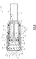
- a fluid connection R2 in accordance with a second embodiment of the invention, is shown in Figures 8 to 11 .
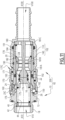
- the fluid connection R2 comprises a fluid connection element 200, which is shown isolated at figure 8 , while the fluid connection element 200 and the complementary tip 10 are shown in Figures 9 to 11 , which illustrate a coupling sequence of the fluid connection element 200 to the complementary tip 10.
- the actuating balls 162 are received in second housings 259 which are not elongated, but only radial.
- the fluid connection element 200 of the second embodiment does not comprise a spacer ring 178.
- first and second seals 191 and 192 are respectively received in first and second sealing housings 191A and 192A which are not “open grooves” but which are here “closed grooves”, directly formed respectively in the distal part 140 and the proximal part 110. More precisely, the first sealing housing 191A is formed in a hollow in the second internal radial surface 122, facing the terminal external radial surface 154 of the distal part 140.
- the terminal external radial surface 154 forms a third external radial surface of the distal part 140, this third external radial surface being substantially complementary to the second internal radial surface 122 of the proximal part 110 and cooperating with reduced radial clearance with the second internal radial surface 122 in the assembled configuration of the body. 102.
- valve 182 in the closed position is directly in front abutment against the distal part 140 of the body 102.
- the actuating collar 24 pushes the actuating balls 162 radially, the actuating balls 162 coming into contact with the front surface 177B of the locking ring 170 and pushing the locking ring 170 longitudinally rearward, until the actuating collar 24 comes into contact with the locking balls 160 and is inserted under the actuating balls 162.
- the actuating collar 24 pushes the locking balls 160 towards their release position, according to a radial movement towards the outside, that is to say centrifugal to the main axis A100.
- This radial movement brings the locking balls 160 into contact with the front surface 177B and drives the locking ring 170 towards the rear towards the retracted unlocking position until the groove 176 allows the locking balls 160 to reach their release position.
- the actuating collar 24 is then introduced under the locking balls 160, as illustrated in figure 10 .
- the locking groove 26 comes level with the actuating balls 162, which are free to engage in the locking groove 26. Then, when the locking groove 26 is level with the locking balls 160, these engage in the locking groove 26.
- the locking ring 170 is then pushed back towards its advanced retaining position by the locking spring 171, and the locking surface 175 comes to cover the locking balls 160 in the locking position, locking the male body 12.
- the fluid connector R2 is then in the coupled configuration, as illustrated in FIG. figure 11 .
- the locking ring 170 in the uncoupled configuration, when the locking ring 170 is in the advanced retaining position, the locking ring 170 is in front abutment directly against the body 102, precisely in front abutment against a shoulder 142A of the distal part 140 - and not against the actuating balls 162, as is the case in the first embodiment -, which limits the movement of the locking ring 170 forward relative to the body 102.
- the locking ring 170 is pulled back by the operator against the locking spring 171 into the retracted unlocking position, the locking balls 160 and actuating balls 162 being free to move apart in the groove 176, thus freeing the passage for the male body 12 out of the female body 102.
- a fluid connection element 300 belonging to a fluid connection according to a third embodiment of the invention is shown in figures 12 And 13 .
- the elastic obstacle used for assembling the proximal portion 110 and the distal portion 140 is a split ring 190
- the elastic obstacle used for assembling the proximal portion 110 and the distal portion 140 is a ring 390, which is made of metal and which comprises elastically deformable teeth, by bending.
- the ring 390 is for example manufactured by providing notches and holes in an initially cylindrical ring centered on a ring axis A390, so as to cut out teeth 391, here each of substantially parallelepiped shape, and a cylindrical portion 392, which is here formed by a succession of T-shaped elements 393.
- Each tooth 391 is attached to the cylindrical portion 392 by a front side, while a rear side of each tooth 391 is distant from the ring axis A390, so as to induce plastic deformation of the material at the junction between each tooth 391 and the cylindrical portion 392.
- the shapes of the first internal groove 130 and first external groove 150 are modified accordingly to cooperate with the ring 390.
- the ring 390 is first positioned in the external groove 150, before introducing the subassembly comprising the distal portion 140 and the ring 390 to the subassembly comprising the proximal portion 110.
- the ring 390 is shown in a free configuration, in which no external force - apart from possibly gravity - is applied to the ring 390.
- the teeth 391 are geometrically carried by a cone which is centered on the ring axis A390 and which diverges towards the rear of the ring 390.
- the cylindrical portion 392 In the free configuration of the ring 390, the cylindrical portion 392, and by extension the ring 390, has an internal diameter D392, which is equal to a minimum value.
- the minimum value of the internal diameter D392 is substantially equal to a diameter of the bottom 152A of the external groove 150, as illustrated in figure 12c ).
- the second external radial surface 148 of the distal portion 140 has an external diameter greater than the minimum value of the internal diameter D392 of the ring 390.
- the geometry of the ring 390, with regular notches distributed around the ring axis A390, makes it possible to widen the ring 390 by elastic deformation, in other words makes it possible to increase the internal diameter D392, so as to allow the mounting of the ring 390 in the external groove 150 of the distal portion 140 from the rear of the distal portion 140 of the body 102.
- the ring 390 Once the ring 390 is aligned longitudinally with the external groove 150, the ring 390 returns, by elastic return, to its free configuration, the cylindrical portion 392 being essentially received in the external groove 150, while the teeth 391 protrude, radially outwards, from the external groove 150.
- the ring axis A390 is then aligned with the central axis A100.
- the first internal radial surface 121 of the proximal portion 110 elastically deforms the teeth 391 by bending towards the central axis A100.
- the ring 390 is then entirely contained in the external groove 150.
- the teeth 391 redeploy, by elastic return, as soon as the internal groove 130 is radially opposite the entire length of the teeth 391 of the ring 390.
- the proximal 110 and distal 140 portions are then in an assembled configuration, as illustrated in FIG. figure 12c ). Unlike the previous embodiments, in the third embodiment, no tooling is necessary to hold the obstacle in the external groove 150 during assembly of the body 102.
- the ring 390 cooperates with both the distal axial wall 131D of the inner groove 130 and the proximal axial wall 152B of the outer groove 150, to prevent separation. More specifically, the teeth 391 cooperate with the distal axial wall 131D, while the cylindrical portion 392 cooperates with the proximal axial wall 152B, which blocks the separation movement of the proximal 110 and distal 140 portions.
- the ring 390 is also in external contact with the bottom surface 131A.
- a dimensional clearance 394 is provided between the ring 390 and the internal groove 130, so that the ring 390 is not further deformed radially inwards.
- the ring 390 simply cooperates with the cylindrical bottom surface 131A of the internal groove 130.
- the teeth 391 do not touch the cylindrical bottom surface 131A of the first internal groove 130.
- a maximum external diameter D390 of the ring 390, taken at the end of the teeth 391, in the free state of the ring 390, is less than the diameter of the bottom surface 131A.
- a fluid connection R4 in accordance with a fourth embodiment of the invention, is shown in figure 14 , in coupled configuration.
- the R4 quick connector comprises a fluid connection element 400, coupled to the complementary tip 10.
- the fluid connection element 400 of the fourth embodiment resembles the fluid connection element 100 of the first embodiment in that the balls actuating elements 162 are housed in elongated housings 159, but differs from the fluid connection element 100 of the first embodiment in that the fluid connection element 400 does not include a spacer ring 178, thereby resembling the fluid connection element 200 of the second embodiment.
- the first and second sealing housings 191A and 192A receiving the first and second seals 191 and 192 are “closed grooves”, as in the second embodiment, while the valve 182 in the closed position is in front abutment directly against the distal portion 140.
- the proximal collar 181C of the piston 180 is interposed longitudinally between the distal portion 140 and the proximal portion 110, insofar as the proximal collar 181C faces rearwardly to a surface of the proximal portion 110 and forwardly to a surface of the distal portion 140.
- the proximal portion 110 is exclusively disposed around the distal portion 140. In other words, no surface of the proximal portion 110 is disposed inside the distal portion 140.
- the simplicity and compactness of the assembly of the proximal 110 and distal 140 parts of the body 102 by the deformable obstacle 190 or 390 can be advantageously implemented in a fluid connection element 100 whose locking with the complementary tip 10 during coupling is not automatic, in particular in a connector not comprising actuating balls. In this case, it is necessary for the operator to move the locking ring 170 from the advanced retaining position to the retracted unlocking position to couple the fluid connection element 100 and the complementary tip 10.
- the embodiments and variants mentioned above can be combined with each other to generate new embodiments of the invention.
Landscapes
- Engineering & Computer Science (AREA)
- General Engineering & Computer Science (AREA)
- Mechanical Engineering (AREA)
- Quick-Acting Or Multi-Walled Pipe Joints (AREA)
- Check Valves (AREA)
Applications Claiming Priority (1)
| Application Number | Priority Date | Filing Date | Title |
|---|---|---|---|
| FR2307467A FR3151071A1 (fr) | 2023-07-12 | 2023-07-12 | Élément de raccord fluidique et raccord fluidique associé |
Publications (2)
| Publication Number | Publication Date |
|---|---|
| EP4491926A1 true EP4491926A1 (de) | 2025-01-15 |
| EP4491926B1 EP4491926B1 (de) | 2025-11-12 |
Family
ID=88412930
Family Applications (1)
| Application Number | Title | Priority Date | Filing Date |
|---|---|---|---|
| EP24188426.1A Active EP4491926B1 (de) | 2023-07-12 | 2024-07-12 | Fluidanschlusselement und fluidanschluss dafür |
Country Status (7)
| Country | Link |
|---|---|
| US (1) | US12516762B2 (de) |
| EP (1) | EP4491926B1 (de) |
| CN (1) | CN119309084A (de) |
| CA (1) | CA3247391A1 (de) |
| FR (1) | FR3151071A1 (de) |
| PL (1) | PL4491926T3 (de) |
| TW (1) | TW202517925A (de) |
Families Citing this family (1)
| Publication number | Priority date | Publication date | Assignee | Title |
|---|---|---|---|---|
| TWI879555B (zh) * | 2024-05-10 | 2025-04-01 | 富世達股份有限公司 | 快速接頭 |
Citations (6)
| Publication number | Priority date | Publication date | Assignee | Title |
|---|---|---|---|---|
| DE3023377A1 (de) | 1980-06-23 | 1982-01-14 | Carl Kurt Walther Gmbh & Co Kg, 5600 Wuppertal | Schnellkupplung, insbesondere schnellverschlusskupplung |
| DE2626668C2 (de) * | 1975-06-16 | 1986-11-27 | Kjell Ronny Zug Ekman | Rohr- oder Schlauchleitungskupplung |
| US4949745A (en) | 1988-12-27 | 1990-08-21 | Air-Lock, Incorporated | Clean air connector |
| US6776187B1 (en) * | 2003-03-06 | 2004-08-17 | Parker-Hannifin Corporation | Quick coupling with pressure assist piston |
| EP2674658A1 (de) | 2012-06-15 | 2013-12-18 | Staubli Faverges | Fluidkupplungselement und entsprechende Anordnung |
| US20200363000A1 (en) * | 2019-05-14 | 2020-11-19 | Staubli Faverges | Female element and fluid connection |
Family Cites Families (30)
| Publication number | Priority date | Publication date | Assignee | Title |
|---|---|---|---|---|
| US2708589A (en) * | 1949-05-11 | 1955-05-17 | Robert W Masek | Tension actuated pipe coupling |
| DE2333620C2 (de) * | 1973-07-02 | 1985-08-01 | Kernforschungszentrum Karlsruhe Gmbh, 7500 Karlsruhe | Schnellkupplung für eine kombinierte Luft- und Sprechverbindung |
| US4086939A (en) * | 1976-09-03 | 1978-05-02 | Snap-Tite, Inc. | Coupling assembly |
| US4289164A (en) * | 1978-03-08 | 1981-09-15 | Ekman Engineering Ag | Coupling device |
| US4815495A (en) * | 1986-04-10 | 1989-03-28 | Preece Incorporated | Quick disconnect having reduced fluid pressure drop |
| DK340186D0 (da) * | 1986-07-17 | 1986-07-17 | Nitodan As | Regulerbar sikkerhedskobling |
| SE454722B (sv) * | 1986-10-22 | 1988-05-24 | Stromdahl Leif | Anordning vid koppling for forbindelse av vetskeledningar med insticks- resp mottagningsnippel |
| US4892117A (en) * | 1988-11-10 | 1990-01-09 | Aeroquip Corporation | Refrigeration coupling |
| US5240023A (en) * | 1991-04-08 | 1993-08-31 | Gad Shelef | Safety hose coupler |
| EP0862710B1 (de) * | 1995-11-20 | 2000-08-23 | Aeroquip Corporation | Weibliches kupplungselement mit geringer leckrate |
| JP3556116B2 (ja) * | 1999-02-12 | 2004-08-18 | サーパス工業株式会社 | 液状物等移送用コネクタ−のソケット |
| EP1300623B1 (de) * | 2001-02-28 | 2010-05-12 | Nitto Kohki Co., Ltd. | Rohrverbindung |
| JP4035695B2 (ja) * | 2001-04-12 | 2008-01-23 | Smc株式会社 | 管継手 |
| JP4273487B2 (ja) * | 2003-08-27 | 2009-06-03 | Smc株式会社 | 管継手 |
| FR2889728B1 (fr) * | 2005-08-10 | 2007-10-05 | Staubli Faverges Sca | Ensemble de raccord pour circuit fluidique |
| JP4787682B2 (ja) * | 2006-06-02 | 2011-10-05 | 日東工器株式会社 | 継手及びこの継手に用いるソケット |
| JP5317760B2 (ja) * | 2008-02-28 | 2013-10-16 | 日東工器株式会社 | 管継手用のソケット及び管継手 |
| TW201000793A (en) * | 2008-02-28 | 2010-01-01 | Nitto Kohki Co | Socket for pipe joint and pipe joint |
| JP5319162B2 (ja) * | 2008-05-23 | 2013-10-16 | サーパス工業株式会社 | 管継手 |
| WO2014087187A1 (en) * | 2012-12-06 | 2014-06-12 | Parker Hannifin Manufacturing France Sas | Quick connection coupling assembly |
| ITMI20130524A1 (it) * | 2013-04-05 | 2014-10-06 | Alfa Gomma S P A | Innesto rapido per fluido in pressione |
| KR20170094444A (ko) * | 2015-06-26 | 2017-08-17 | 니토 코키 가부시키가이샤 | 슬라이드 밸브, 그 슬라이드 밸브를 구비하는 암형 조인트 부재, 및 그 암형 조인트 부재와 수형 조인트 부재로 이루어지는 관 조인트 |
| DE102015222640B4 (de) * | 2015-11-17 | 2021-08-26 | U.M. Gewerbeimmobilien Gmbh & Co. Kg | Kupplungselement und Ventilstößel für eine Kupplung zur Verbindung von Druckmittelleitungen |
| FR3046211B1 (fr) * | 2015-12-23 | 2018-02-16 | Staubli Sa Ets | Element male ou femelle de raccord rapide et raccord rapide comprenant un tel element |
| CN107906289A (zh) * | 2017-12-22 | 2018-04-13 | 新乡平原航空液压设备有限公司 | 接头组件及其母接头、公接头 |
| EP3922878B1 (de) * | 2019-02-04 | 2024-03-06 | Nitto Kohki Co., Ltd. | Rohrverbindung mit ventil und schraubenfeder dafür |
| CN110500463B (zh) * | 2019-07-17 | 2021-08-20 | 华为技术有限公司 | 一种接头、冷却系统和计算机装置 |
| FR3099224B1 (fr) * | 2019-07-26 | 2021-08-06 | Staubli Sa Ets | Élément mâle de raccord fluidique, raccord fluidique comprenant un tel élément mâle et procédé d’assemblage d’un tel élément mâle |
| US11486528B2 (en) * | 2019-11-15 | 2022-11-01 | Parker-Hannifin Corporation | Quick-coupling with automatic locking mechanism |
| US20230213128A1 (en) * | 2022-01-03 | 2023-07-06 | Chia Cherne Industry Co., Ltd. | Quick connector |
-
2023
- 2023-07-12 FR FR2307467A patent/FR3151071A1/fr active Pending
-
2024
- 2024-07-08 CA CA3247391A patent/CA3247391A1/fr active Pending
- 2024-07-11 US US18/770,449 patent/US12516762B2/en active Active
- 2024-07-11 TW TW113125966A patent/TW202517925A/zh unknown
- 2024-07-11 CN CN202410927819.6A patent/CN119309084A/zh active Pending
- 2024-07-12 PL PL24188426.1T patent/PL4491926T3/pl unknown
- 2024-07-12 EP EP24188426.1A patent/EP4491926B1/de active Active
Patent Citations (6)
| Publication number | Priority date | Publication date | Assignee | Title |
|---|---|---|---|---|
| DE2626668C2 (de) * | 1975-06-16 | 1986-11-27 | Kjell Ronny Zug Ekman | Rohr- oder Schlauchleitungskupplung |
| DE3023377A1 (de) | 1980-06-23 | 1982-01-14 | Carl Kurt Walther Gmbh & Co Kg, 5600 Wuppertal | Schnellkupplung, insbesondere schnellverschlusskupplung |
| US4949745A (en) | 1988-12-27 | 1990-08-21 | Air-Lock, Incorporated | Clean air connector |
| US6776187B1 (en) * | 2003-03-06 | 2004-08-17 | Parker-Hannifin Corporation | Quick coupling with pressure assist piston |
| EP2674658A1 (de) | 2012-06-15 | 2013-12-18 | Staubli Faverges | Fluidkupplungselement und entsprechende Anordnung |
| US20200363000A1 (en) * | 2019-05-14 | 2020-11-19 | Staubli Faverges | Female element and fluid connection |
Also Published As
| Publication number | Publication date |
|---|---|
| PL4491926T3 (pl) | 2026-03-23 |
| EP4491926B1 (de) | 2025-11-12 |
| TW202517925A (zh) | 2025-05-01 |
| CN119309084A (zh) | 2025-01-14 |
| FR3151071A1 (fr) | 2025-01-17 |
| US20250020253A1 (en) | 2025-01-16 |
| US12516762B2 (en) | 2026-01-06 |
| CA3247391A1 (de) | 2025-06-06 |
Similar Documents
| Publication | Publication Date | Title |
|---|---|---|
| EP0715111B1 (de) | Schnellverbindungsvorrichtung zum Kuppeln eines Rohres auf einem starren Ansatzstück | |
| EP2439440B1 (de) | Anschlussvorrichtung mit Verriegelung durch Gewindegriffe, und Anschluss, der eine solche Vorrichtung enthält | |
| EP3184870B1 (de) | Buchse eines schnellanschlusses, und eine solche buchse umfassender schnellanschluss | |
| EP0665401B1 (de) | Schnellverbindung | |
| EP3196526B1 (de) | Schnellkupplung für die lösbare verbindung von leitungen für fluide unter druck | |
| EP3220034B1 (de) | Kupplungselement für die verbindung von flüssigkeitsführenden bauteilen und kupplung mit einem solchen element. | |
| EP4056883B1 (de) | Buchse eines schnellanschlusses, und schnellanschluss, der eine solche buchse und einen entsprechenden stecker umfasst | |
| EP3670992B1 (de) | Anschlussbuchse und fluidanschluss, der ein steckanschlusselement sowie diese anschlussbuchse umfasst | |
| EP3599408B1 (de) | Schnellkupplung für die lösbare verbindung von zwei rohren, durch die eine flüssigkeit unter druck fliesst | |
| EP4306837B1 (de) | Anschlusselement für eine fluidverbindung an ein endgerät | |
| EP4491926B1 (de) | Fluidanschlusselement und fluidanschluss dafür | |
| EP4124788A1 (de) | Steckanschlusselement eines fluidanschlusses und ein solches steckelement umfassender fluidanschluss | |
| EP4421371A1 (de) | Schnellkupplungsbuchse und zugehörige schnellkupplung | |
| FR2836203A1 (fr) | Raccord destine a relier des conduites hydrauliques | |
| EP2587109A1 (de) | Anschlussvorrichtung | |
| EP4166836A1 (de) | Schnellkupplung und verbindungsanordnung mit einer solchen schnellkupplung | |
| EP4004420B1 (de) | Steckelement für eine fluidische kupplung, fluidische kupplung mit einem solchen steckelement und verfahren zum zusammenbau eines solchen steckelements | |
| EP3599409B1 (de) | Schnellkupplung für die lösbare verbindung von zwei leitungen, durch die eine flüssigkeit unter druck fliesst | |
| EP3798490B1 (de) | Fluidanschlusselement | |
| EP4336080A1 (de) | Schnellkupplungsbuchse | |
| EP4685379A1 (de) | Fluidverbindungselement und -anordnung | |
| EP4592575A1 (de) | Fluidanschlusselement und fluidkupplung mit einem solchen fluidanschlusselement | |
| EP4556775A1 (de) | Fluidanschlussbuchse | |
| EP4682418A1 (de) | Schutzschalter und druckflüssigkeitshandhabungsanlage mit einem solchen schutzschalter | |
| EP4656924A1 (de) | Fluidanschlusselement und fluidanschluss |
Legal Events
| Date | Code | Title | Description |
|---|---|---|---|
| PUAI | Public reference made under article 153(3) epc to a published international application that has entered the european phase |
Free format text: ORIGINAL CODE: 0009012 |
|
| STAA | Information on the status of an ep patent application or granted ep patent |
Free format text: STATUS: THE APPLICATION HAS BEEN PUBLISHED |
|
| AK | Designated contracting states |
Kind code of ref document: A1 Designated state(s): AL AT BE BG CH CY CZ DE DK EE ES FI FR GB GR HR HU IE IS IT LI LT LU LV MC ME MK MT NL NO PL PT RO RS SE SI SK SM TR |
|
| STAA | Information on the status of an ep patent application or granted ep patent |
Free format text: STATUS: REQUEST FOR EXAMINATION WAS MADE |
|
| 17P | Request for examination filed |
Effective date: 20250617 |
|
| GRAP | Despatch of communication of intention to grant a patent |
Free format text: ORIGINAL CODE: EPIDOSNIGR1 |
|
| STAA | Information on the status of an ep patent application or granted ep patent |
Free format text: STATUS: GRANT OF PATENT IS INTENDED |
|
| INTG | Intention to grant announced |
Effective date: 20250728 |
|
| GRAS | Grant fee paid |
Free format text: ORIGINAL CODE: EPIDOSNIGR3 |
|
| GRAA | (expected) grant |
Free format text: ORIGINAL CODE: 0009210 |
|
| STAA | Information on the status of an ep patent application or granted ep patent |
Free format text: STATUS: THE PATENT HAS BEEN GRANTED |
|
| AK | Designated contracting states |
Kind code of ref document: B1 Designated state(s): AL AT BE BG CH CY CZ DE DK EE ES FI FR GB GR HR HU IE IS IT LI LT LU LV MC ME MK MT NL NO PL PT RO RS SE SI SK SM TR |
|
| REG | Reference to a national code |
Ref country code: CH Ref legal event code: F10 Free format text: ST27 STATUS EVENT CODE: U-0-0-F10-F00 (AS PROVIDED BY THE NATIONAL OFFICE) Effective date: 20251112 Ref country code: GB Ref legal event code: FG4D Free format text: NOT ENGLISH |
|
| REG | Reference to a national code |
Ref country code: DE Ref legal event code: R096 Ref document number: 602024001248 Country of ref document: DE |
|
| REG | Reference to a national code |
Ref country code: IE Ref legal event code: FG4D Free format text: LANGUAGE OF EP DOCUMENT: FRENCH |
|
| P01 | Opt-out of the competence of the unified patent court (upc) registered |
Free format text: CASE NUMBER: UPC_APP_0012097_4491926/2025 Effective date: 20251105 |
|
| REG | Reference to a national code |
Ref country code: SE Ref legal event code: TRGR |
|
| REG | Reference to a national code |
Ref country code: NL Ref legal event code: MP Effective date: 20251112 |
|
| PG25 | Lapsed in a contracting state [announced via postgrant information from national office to epo] |
Ref country code: ES Free format text: LAPSE BECAUSE OF FAILURE TO SUBMIT A TRANSLATION OF THE DESCRIPTION OR TO PAY THE FEE WITHIN THE PRESCRIBED TIME-LIMIT Effective date: 20251112 |
|
| REG | Reference to a national code |
Ref country code: LT Ref legal event code: MG9D |
|
| PG25 | Lapsed in a contracting state [announced via postgrant information from national office to epo] |
Ref country code: NO Free format text: LAPSE BECAUSE OF FAILURE TO SUBMIT A TRANSLATION OF THE DESCRIPTION OR TO PAY THE FEE WITHIN THE PRESCRIBED TIME-LIMIT Effective date: 20260212 |
|
| PG25 | Lapsed in a contracting state [announced via postgrant information from national office to epo] |
Ref country code: AT Free format text: LAPSE BECAUSE OF FAILURE TO SUBMIT A TRANSLATION OF THE DESCRIPTION OR TO PAY THE FEE WITHIN THE PRESCRIBED TIME-LIMIT Effective date: 20251112 Ref country code: FI Free format text: LAPSE BECAUSE OF FAILURE TO SUBMIT A TRANSLATION OF THE DESCRIPTION OR TO PAY THE FEE WITHIN THE PRESCRIBED TIME-LIMIT Effective date: 20251112 Ref country code: HR Free format text: LAPSE BECAUSE OF FAILURE TO SUBMIT A TRANSLATION OF THE DESCRIPTION OR TO PAY THE FEE WITHIN THE PRESCRIBED TIME-LIMIT Effective date: 20251112 |
|
| REG | Reference to a national code |
Ref country code: AT Ref legal event code: MK05 Ref document number: 1856987 Country of ref document: AT Kind code of ref document: T Effective date: 20251112 |
|
| PG25 | Lapsed in a contracting state [announced via postgrant information from national office to epo] |
Ref country code: NL Free format text: LAPSE BECAUSE OF FAILURE TO SUBMIT A TRANSLATION OF THE DESCRIPTION OR TO PAY THE FEE WITHIN THE PRESCRIBED TIME-LIMIT Effective date: 20251112 |
|
| PG25 | Lapsed in a contracting state [announced via postgrant information from national office to epo] |
Ref country code: RS Free format text: LAPSE BECAUSE OF FAILURE TO SUBMIT A TRANSLATION OF THE DESCRIPTION OR TO PAY THE FEE WITHIN THE PRESCRIBED TIME-LIMIT Effective date: 20260212 |
|
| PG25 | Lapsed in a contracting state [announced via postgrant information from national office to epo] |
Ref country code: IS Free format text: LAPSE BECAUSE OF FAILURE TO SUBMIT A TRANSLATION OF THE DESCRIPTION OR TO PAY THE FEE WITHIN THE PRESCRIBED TIME-LIMIT Effective date: 20260312 |