EP2675593B1 - Appareil permettant de resserrer des éléments de fixation filetés - Google Patents
Appareil permettant de resserrer des éléments de fixation filetés Download PDFInfo
- Publication number
- EP2675593B1 EP2675593B1 EP12708429.1A EP12708429A EP2675593B1 EP 2675593 B1 EP2675593 B1 EP 2675593B1 EP 12708429 A EP12708429 A EP 12708429A EP 2675593 B1 EP2675593 B1 EP 2675593B1
- Authority
- EP
- European Patent Office
- Prior art keywords
- assembly
- rotatably
- clamp assembly
- tool assembly
- reaction
- Prior art date
- Legal status (The legal status is an assumption and is not a legal conclusion. Google has not performed a legal analysis and makes no representation as to the accuracy of the status listed.)
- Active
Links
Images

Classifications
-
- B—PERFORMING OPERATIONS; TRANSPORTING
- B25—HAND TOOLS; PORTABLE POWER-DRIVEN TOOLS; MANIPULATORS
- B25B—TOOLS OR BENCH DEVICES NOT OTHERWISE PROVIDED FOR, FOR FASTENING, CONNECTING, DISENGAGING OR HOLDING
- B25B23/00—Details of, or accessories for, spanners, wrenches, screwdrivers
- B25B23/0078—Reaction arms
-
- B—PERFORMING OPERATIONS; TRANSPORTING
- B23—MACHINE TOOLS; METAL-WORKING NOT OTHERWISE PROVIDED FOR
- B23P—METAL-WORKING NOT OTHERWISE PROVIDED FOR; COMBINED OPERATIONS; UNIVERSAL MACHINE TOOLS
- B23P19/00—Machines for simply fitting together or separating metal parts or objects, or metal and non-metal parts, whether or not involving some deformation; Tools or devices therefor so far as not provided for in other classes
- B23P19/04—Machines for simply fitting together or separating metal parts or objects, or metal and non-metal parts, whether or not involving some deformation; Tools or devices therefor so far as not provided for in other classes for assembling or disassembling parts
- B23P19/06—Screw or nut setting or loosening machines
- B23P19/069—Multi-spindle machines
-
- B—PERFORMING OPERATIONS; TRANSPORTING
- B25—HAND TOOLS; PORTABLE POWER-DRIVEN TOOLS; MANIPULATORS
- B25B—TOOLS OR BENCH DEVICES NOT OTHERWISE PROVIDED FOR, FOR FASTENING, CONNECTING, DISENGAGING OR HOLDING
- B25B21/00—Portable power-driven screw or nut setting or loosening tools; Attachments for drilling apparatus serving the same purpose
- B25B21/004—Portable power-driven screw or nut setting or loosening tools; Attachments for drilling apparatus serving the same purpose of the ratchet type
- B25B21/005—Portable power-driven screw or nut setting or loosening tools; Attachments for drilling apparatus serving the same purpose of the ratchet type driven by a radially acting hydraulic or pneumatic piston
-
- B—PERFORMING OPERATIONS; TRANSPORTING
- B25—HAND TOOLS; PORTABLE POWER-DRIVEN TOOLS; MANIPULATORS
- B25H—WORKSHOP EQUIPMENT, e.g. FOR MARKING-OUT WORK; STORAGE MEANS FOR WORKSHOPS
- B25H1/00—Work benches; Portable stands or supports for positioning portable tools or work to be operated on thereby
- B25H1/0021—Stands, supports or guiding devices for positioning portable tools or for securing them to the work
- B25H1/0057—Devices for securing hand tools to the work
Definitions
- Novel reaction fixtures and adaptors are known through recent patent application disclosures and applied to inverted applications such as for example underground mining, excavation and tunneling operations. Need exists for novel reaction fixture solutions for inverted socket head cap screw (SHCS) bolting applications, particularly joint closure at main stop valve (MSV) pressure seal heads.
- SHCS inverted socket head cap screw
- MSV main stop valve
- US 5,791,619 is directed to a tool suspension arm having a housing defining an axially extensive cavity open at one end.
- An axially extensive rod is received by the axially extensive cavity through the open end for slidable axial movement relative to the housing.
- the axially extensive rod is splined and is closed in the axially extensive cavity of the housing by a splined hub insert inserted over the axially extensive rod into the open end of the axially extensive cavity.
- the invention described in US 2,737,065 relates to tool attachments and more particularly to an attachment wherein a conventional power driven hand drill may be utilized in the manner of a portable or stationary drill press.
- EP 1 428 972 A2 discloses an apparatus comprising a drill and an arrangement of rods that can be axially displaced and positioned along a bottom of a building by means of a drive device.
- the apparatus further includes a holder for the drill and is provided with an end portion and an elastic support member, preferably including a spiral spring. Under force a supporting member is pressed against the the roof of the building by moving the arrangement of rods.
- the present invention has therefore been devised to address these issues.
- Apparatus for use with a tool assembly in operations of tightening or loosening threaded fasteners about an axis are disclosed, and in one example includes: a lower clamp assembly; an upper clamp assembly; a reaction adaptor assembly; and a spring assembly formed between the upper clamp assembly and the reaction adaptor assembly.
- a lower clamp assembly eliminates the need for extra operators and heavy and bulky equipment to hold the apparatus near the fasteners.
- the upper clamp allows the operator to rotate the apparatus around with ease.
- the spring assembly stabilizes and eases vertical height adjustment of the apparatus.
- the reaction adaptor substantially negates reaction turning forces of the tool assembly during the operations. Drive knobs provide easy alignment of and quick and safe mounting of the tool assembly on the fasteners. Bolting operations about an axis are completed faster, cheaper and with little or no risk of operator injury.
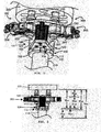
- FIG. 1 shows first aspect of the invention.
- Location 200 includes a pipe stem 210, a flange 220, and fasteners, or SHCSs 230.
- Apparatus 100 includes a lower clamp assembly 110, an upper clamp assembly 120, a reaction adaptor assembly 130 and a spring assembly 140 formed between upper clamp assembly 120 and reaction adaptor assembly 130.
- Lower clamp assembly 110 such as for example a fixed clamp, includes an annular hollow body 111 which has a first portion 112 and a second portion 113. First and second portions 112 and 113 are connected on one side by a hinge (not shown) and connected on the other side by a closing mechanism 114, such as for example a setscrew.
- Lower clamp assembly 110 is non-rotatably connected to and may have an interference fit against pipe stem 210 which prevents vertical and rotational movement upon installation.
- Lower clamp assembly 110 is used to set apparatus 100 and tool assembly 300 at a pre-determined height H 100 needed to engage male hex sockets 311 and 321 in the cap screws of fasteners 230. Note that lower clamp assembly 110 has a height H 110 . Lower clamp assembly 110 makes the apparatus hands free after setup.
- Upper clamp assembly 120 such as for example an adjustable clamp, includes an annular hollow body 121 which has a first portion 123 and a second portion 122.
- First portion 123 includes a platform 124.
- First and second portions 123 and 122 are connected in a similar manner as first and second portions 112 and 113 of lower clamp assembly 110.
- hinge 126 connects first and second portions 123 and 122.
- Upper clamp assembly 120 is rotatably connected to pipe stem 210 by tightening a closing mechanism (not shown in the FIGs.), such as for example a setscrew. This closure results in a loose tolerance which allows upper clamp assembly 120 to rotate around the axis of pipe stem 210.
- Upper clamp assembly rests also on yet is also rotatable around lower clamp assembly 110.
- Upper clamp assembly 120 is used to set apparatus 100 and tool assembly 300 at a pre-determined height H 120 needed to engage male hex sockets 311 and 321 in the cap screws of fasteners 230.
- annular hollow body 121 has a height H 121 .
- platform 124 may be formed as any suitable shape and with any suitable dimension, and in this case is formed as a trapezoid.
- Reaction adaptor assemblies are thoroughly disclosed and discussed in commonly owned international patent application PCT/US10/032139, having filing date of April 23, 2010 , that is entitled "Apparatus for Tightening or Loosening Fasteners" (the '139 Application), an entire copy of which is incorporated herein by reference.
- Such reaction adaptor assemblies are used in commerce under Applicant's trade name TWIN TORQUE ® .
- Reaction adaptor assembly 130 a type similar to those described in the '139 Application, connects tools 310 and 320 such that the reaction forces created during operation are absorbed and cancel one another. The torque being applied to fasteners 230, and therefore the reaction forces, are substantially equal and opposite. Note that various changes, combinations, alterations, and variations of aspects of the '139 Application may be used in conjunction with the present invention.
- Spring assembly 140 Formed between and connecting platform 124 of upper clamp assembly 120 and reaction adaptor assembly 130 is a spring assembly 140.
- Spring assembly 140 includes three spring coils with telescoping cores which allows reaction adaptor assembly 130 and therefore tools 310 and 320 and other ancillary components including hex sockets 311 and 321 and drive knobs 312 and 322 to move up and down.
- Spring assembly 140 keeps constant pressure on reaction adaptor assembly 130 and therefore tool assembly 300 to maintain engagement of male hex sockets 311 and 321 and SHCSs 230 at location 200.
- spring assembly 140 allows male hex sockets 311 and 321 to be removed from SHCSs 230 upon loosening.
- An operator is able to remove male hex sockets 311 and 321 from one set of SHCSs 230 and rotate and replace the sockets onto another set of SHCSs 230. The operator can thus tighten all the SHCSs 230 at location 200 without having to change the initial setup.
- FIG. 2 shows various heights associated with apparatus 100.
- H 100 indicates the distance between a lower face of lower clamp assembly 110 and a lower face of flange 220.
- H 110 indicates the height of lower clamp assembly 110.
- H 120 indicates the height of upper clamp assembly 120.
- H 130 indicates the distance between a lower face of reaction assembly 130 and a lower face of flange 220.
- H 140 indicates the variable height of spring assembly 140. Note that H 200 and H 210 are arbitrary distances dependent on characteristics further along pipe stem 210.
- the operator orients male hex sockets 311 and 321 with the female hex engagements of two of SHCSs 230 using drive knobs 312 and 322.
- Drive knobs 312 and 311 allow the operator to turn and position reaction adaptor assembly 130 without removing tools 310 and 320. These hexes, once aligned and positioned, will keep their engagement with the selected two SHCSs 230.
- the operator then tightens or loosens the selected two SHCSs 230 as desired.
- the operator disengages male hex sockets 311 and 321 from the selected two SHCSs 230 by applying pressure to spring assembly 140 then rotates upper clamp assembly 120 and therefore all other attached components to fit two other SHCSs 230 on flange 220. The operator repeats this operation process until all SHCS 230 are tightened or loosened.
- Apparatus 100 includes: lower clamp assembly 110; upper clamp assembly 120; reaction adaptor assembly 130; and spring assembly 140 formed between upper clamp assembly 120 and reaction adaptor assembly 130.
- the operator can tighten or loosen all of SHCSs 230 at location 200 without having to change the initial setup.of apparatus 100.
- Lower clamp assembly 110 eliminates the need for extra operators and heavy and bulky equipment to hold apparatus near location 200.
- Upper clamp 120 allows the operator to rotate apparatus 100 around pipe stem 210 with ease.
- Spring assembly 140 stabilizes and eases vertical height adjustment of apparatus 100.
- Reaction adaptor 130 substantially negates reactionturning forces of tool assembly 300 during the operations.
- Drive knobs 312 and 322 provide easy alignment of and quick and safe mounting of tool assembly 300 on SHCSs 230. Bolting operations about an axis are completed faster, cheaper and with little or no risk of operator injury.
- Apparatus 100 is described in this specification for use with inverted SHCS bolting applications, particularly joint closure at MSV pressure seal heads. Apparatus 100, and modifications thereof, may be used with many other bolting applications.
Landscapes
- Engineering & Computer Science (AREA)
- Mechanical Engineering (AREA)
- Earth Drilling (AREA)
- Details Of Spanners, Wrenches, And Screw Drivers And Accessories (AREA)
- Flanged Joints, Insulating Joints, And Other Joints (AREA)
- Automatic Assembly (AREA)
- Mutual Connection Of Rods And Tubes (AREA)
- Clamps And Clips (AREA)
Claims (9)
- Appareil destiné à être utilisé avec un ensemble d'outil (300) pour des opérations de serrage ou de desserrage d'éléments de fixation vissés (230) autour d'un axe incluant :un ensemble d'attache inférieur (110),un ensemble d'attache supérieur (120),un ensemble d'adaptateur de réaction (130) incluant un élément de transmission de force destiné à s'opposer globalement à des forces tournantes de réaction de l'ensemble d'outil (300) durant les opérations, etun ensemble de ressort (140) formé entre l'ensemble d'attache supérieur (120) et l'ensemble d'adaptateur de réaction (130)dans lequel l'ensemble d'attache inférieur (110) peut être connecté sans possibilité de rotation autour de l'axe,l'ensemble d'attache supérieur (120) peut être connecté avec possibilité de rotation autour de l'axe et de l'ensemble d'attache inférieur (110),l'ensemble d'adaptateur de réaction (130) peut être connecté sans possibilité de rotation à l'ensemble d'attache supérieur (120) et être positionné verticalement par rapport à celui-ci au moyen de l'ensemble de ressort (140), etl'ensemble d'outil (300) peut être connecté sans possibilité de rotation à l'ensemble d'adaptateur de réaction (130) et être connecté avec possibilité de rotation aux éléments de fixation.
- Appareil selon la revendication 1 dans lequel l'ensemble d'attache inférieur (110) inclut un corps creux annulaire (111) ayant une première partie (12) et une deuxième partie (113) qui sont connectées par un premier mécanisme de fermeture et un deuxième mécanisme de fermeture.
- Appareil selon l'une quelconque des revendications précédentes dans lequel l'ensemble d'attache supérieur (120) inclut un corps creux annulaire (121) ayant une première partie (123), une deuxième partie (122) et une plate-forme (124) de la première partie (123) qui sont connectées par un premier mécanisme de fermeture et un deuxième mécanisme de fermeture.
- Appareil selon l'une quelconque des revendications précédentes dans lequel l'ensemble d'attache inférieur (110), l'ensemble d'attache supérieur (120), l'ensemble d'adaptateur de réaction (130), l'ensemble de ressort (140) et l'ensemble d'outil (300) peuvent être fixés séparément, individuellement et indépendamment les uns des autres.
- Appareil selon l'une quelconque des revendications précédentes dans lequel l'ensemble d'adaptateur de réaction (130) inclut :un premier élément de transmission de force soit pouvant être fixé avec possibilité de rotation autour, pouvant être fixé de façon extensible et rétractable le long d'un premier axe de forces tournantes de l'ensemble d'outil (300), soit pouvant être fixé avec possibilité de rotation autour et pouvant être fixé de façon extensible et rétractable le long d'un premier axe de forces tournantes de l'ensemble d'outil (300),un deuxième élément de transmission de force soit pouvant être fixé avec possibilité de rotation autour, pouvant être fixé de façon extensible et rétractable le long d'un deuxième axe de forces tournantes de l'ensemble d'outil (300), soit pouvant être fixé avec possibilité de rotation autour et pouvant être fixé de façon extensible et rétractable le long d'un deuxième axe de forces tournantes de l'ensemble d'outil (300),dans lequel les premier et deuxième éléments, lorsqu'ils sont connectés, s'opposent globalement aux forces tournantes de réaction de l'ensemble d'outil (300) au cours des opérations.
- Appareil destiné à réaliser des opérations de serrage ou de desserrage des éléments de fixation vissés (230) autour d'un axe incluant :un appareil destiné à être utilisé pour de telles opérations selon l'une quelconque des revendications précédentesun ensemble d'outil (300) pouvant être connecté sans possibilité de rotation à l'ensemble d'adaptateur de réaction (130) et pouvant être connecté avec possibilité de rotation aux éléments de fixation (230).
- Appareil selon la revendication 6 dans lequel l'ensemble d'outil (300) inclut :un premier et un deuxième éléments de réception, supportés avec possibilité de rotation dans l'ensemble d'outil (300), pour recevoir un premier et un deuxième éléments de fixation (230),un premier et un deuxième dispositifs destinés à positionner les éléments de réception respectifs pour un engagement sans possibilité de rotation avec les éléments de fixation respectifs (230), etun premier et un deuxième dispositifs destinés à effectuer une rotation des éléments de réception respectifs pour serrer ou desserrer les éléments de fixation respectifs (230).
- Appareil selon la revendication 6 ou 7 incluant un dispositif destiné à contrôler l'ensemble d'outil (300) pour maintenir une différence entre des paramètres opérationnels des éléments de fixation respectifs (230) dans les limites d'une valeur prédéterminée.
- Appareil selon l'une quelconque des revendications 6 à 8 dans lequel l'ensemble d'outil (300) est soit pneumatique, soit électrique, soit hydraulique, soit manuel.
Applications Claiming Priority (2)
| Application Number | Priority Date | Filing Date | Title |
|---|---|---|---|
| US201161443736P | 2011-02-17 | 2011-02-17 | |
| PCT/US2012/025747 WO2012112960A1 (fr) | 2011-02-17 | 2012-02-17 | Appareil permettant de resserrer des éléments de fixation filetés |
Publications (2)
| Publication Number | Publication Date |
|---|---|
| EP2675593A1 EP2675593A1 (fr) | 2013-12-25 |
| EP2675593B1 true EP2675593B1 (fr) | 2015-07-08 |
Family
ID=45815959
Family Applications (1)
| Application Number | Title | Priority Date | Filing Date |
|---|---|---|---|
| EP12708429.1A Active EP2675593B1 (fr) | 2011-02-17 | 2012-02-17 | Appareil permettant de resserrer des éléments de fixation filetés |
Country Status (9)
| Country | Link |
|---|---|
| US (1) | US20130319181A1 (fr) |
| EP (1) | EP2675593B1 (fr) |
| JP (1) | JP5969514B2 (fr) |
| CN (1) | CN103459093B (fr) |
| BR (1) | BR112013020951B1 (fr) |
| EA (1) | EA029378B9 (fr) |
| ES (1) | ES2546432T3 (fr) |
| MX (1) | MX339090B (fr) |
| WO (1) | WO2012112960A1 (fr) |
Cited By (1)
| Publication number | Priority date | Publication date | Assignee | Title |
|---|---|---|---|---|
| EP3450744A1 (fr) * | 2017-08-31 | 2019-03-06 | General Electric Company | Procédés et systèmes pour le démontage d'un palier de pas d'un moyeu d'éolienne |
Families Citing this family (6)
| Publication number | Priority date | Publication date | Assignee | Title |
|---|---|---|---|---|
| DE102013210268B4 (de) * | 2013-06-03 | 2014-12-11 | Wagner Vermögensverwaltungs-GmbH & Co. KG | Sicherungssystem für Kraftschrauber sowie Kraftschrauber |
| NO336519B1 (no) * | 2013-12-19 | 2015-09-14 | Hytorc Norge As | Dreiemomentnøkkelanordning for flere bolter eller mutre for installering eller fjerning av en flerhet av gjengede bolt- eller mutterorganer. |
| US10611004B2 (en) * | 2015-05-11 | 2020-04-07 | HYTORC Division Unex Corporation | Rotation angle indicating retainer assembly for tightening threaded fasteners |
| CN107585573B (zh) * | 2017-08-10 | 2019-04-02 | 中国第一汽车股份有限公司 | 一种适用于牵引盘底板的半自动装配生产线及其装配方法 |
| CN117162045A (zh) * | 2023-10-12 | 2023-12-05 | 江苏一方月文化科技有限公司 | 一种计算机服务器硬件辅助安装装置 |
| CN118650425B (zh) * | 2024-08-20 | 2024-10-18 | 贵州轻工职业技术学院 | 一种接线板导电片锁螺丝装置 |
Family Cites Families (15)
| Publication number | Priority date | Publication date | Assignee | Title |
|---|---|---|---|---|
| US2737065A (en) * | 1953-01-19 | 1956-03-06 | James W Piersall | Portable drill press |
| US3805645A (en) * | 1972-03-07 | 1974-04-23 | R Jenny | Power drive wrench |
| US3810710A (en) * | 1972-08-10 | 1974-05-14 | J Ennemoser | Vehicle wheel stud drill |
| JPS59116172U (ja) * | 1983-01-26 | 1984-08-06 | 三菱重工業株式会社 | ボルト類着脱装置 |
| JPH074770B2 (ja) * | 1989-10-25 | 1995-01-25 | 株式会社クボタ | レンチ装置 |
| US5051044A (en) * | 1990-03-05 | 1991-09-24 | Harold Allen | Pipe drilling apparatus |
| US5791619A (en) | 1996-11-01 | 1998-08-11 | Phd, Inc. | Anti-torque reaction arm |
| US6244138B1 (en) * | 1998-09-01 | 2001-06-12 | Furmanite Worldwide, Inc. | Torque reaction device |
| US6568299B2 (en) * | 1999-12-16 | 2003-05-27 | Bobby Hu | Reversible ratcheting tool with a smaller head |
| CN1148277C (zh) * | 2000-03-23 | 2004-05-05 | 胡厚飞 | 棘轮扳手 |
| US6575060B1 (en) * | 2002-03-18 | 2003-06-10 | Awi Acquisition Company | Reversible ratchet wrench |
| US7108459B1 (en) * | 2002-09-23 | 2006-09-19 | Mueller Thomas L | Power assisted drill press |
| EP1428972A3 (fr) | 2002-12-11 | 2005-01-12 | Zurecon Ag | Dispositif avec au moins une perceuse |
| US20040112597A1 (en) * | 2002-12-13 | 2004-06-17 | Syed Hamid | Packer set monitoring and compensating system and method |
| US20100269645A1 (en) * | 2009-04-22 | 2010-10-28 | HYTORC Division Unex Corporation | Reaction adaptors for torque power tools and methods of using the same |
-
2012
- 2012-02-17 ES ES12708429.1T patent/ES2546432T3/es active Active
- 2012-02-17 BR BR112013020951-8A patent/BR112013020951B1/pt active IP Right Grant
- 2012-02-17 EA EA201300834A patent/EA029378B9/ru not_active IP Right Cessation
- 2012-02-17 JP JP2013554663A patent/JP5969514B2/ja active Active
- 2012-02-17 EP EP12708429.1A patent/EP2675593B1/fr active Active
- 2012-02-17 MX MX2013009530A patent/MX339090B/es active IP Right Grant
- 2012-02-17 WO PCT/US2012/025747 patent/WO2012112960A1/fr not_active Ceased
- 2012-02-17 US US14/000,231 patent/US20130319181A1/en not_active Abandoned
- 2012-02-17 CN CN201280016124.8A patent/CN103459093B/zh active Active
Cited By (2)
| Publication number | Priority date | Publication date | Assignee | Title |
|---|---|---|---|---|
| EP3450744A1 (fr) * | 2017-08-31 | 2019-03-06 | General Electric Company | Procédés et systèmes pour le démontage d'un palier de pas d'un moyeu d'éolienne |
| US10823137B2 (en) | 2017-08-31 | 2020-11-03 | General Electric Renovables Espana, S.L. | Methods and systems for disassembling a pitch bearing from a wind turbine hub |
Also Published As
| Publication number | Publication date |
|---|---|
| ES2546432T3 (es) | 2015-09-23 |
| MX339090B (es) | 2016-05-11 |
| JP2014505601A (ja) | 2014-03-06 |
| BR112013020951A2 (pt) | 2019-03-06 |
| EP2675593A1 (fr) | 2013-12-25 |
| CN103459093B (zh) | 2016-12-21 |
| US20130319181A1 (en) | 2013-12-05 |
| WO2012112960A1 (fr) | 2012-08-23 |
| JP5969514B2 (ja) | 2016-08-17 |
| MX2013009530A (es) | 2014-07-24 |
| EA029378B9 (ru) | 2018-09-28 |
| EA029378B1 (ru) | 2018-03-30 |
| CN103459093A (zh) | 2013-12-18 |
| BR112013020951B1 (pt) | 2022-02-08 |
| EA201300834A1 (ru) | 2014-05-30 |
Similar Documents
| Publication | Publication Date | Title |
|---|---|---|
| EP2675593B1 (fr) | Appareil permettant de resserrer des éléments de fixation filetés | |
| US9663304B2 (en) | Rotary chuck | |
| US9254722B2 (en) | Tool for supporting and locking a rim or tired wheel for motorcycles | |
| CN208840846U (zh) | 一种螺栓拆装工具 | |
| CN106826604A (zh) | 便携式工件夹持装置及组件 | |
| CN104264997A (zh) | 一种新型钢筋连接装置 | |
| US20170211614A1 (en) | Articulating Attachment for Extension Poles | |
| CN107009304B (zh) | 法兰对正工具及操作方法 | |
| CN204081522U (zh) | 一种新型钢筋连接装置 | |
| JP6529959B2 (ja) | ネジ締め装置およびネジ締めシステム | |
| CN104246148A (zh) | 涡轮机加长螺母支撑工具 | |
| US11358261B2 (en) | Apparatus for tightening threaded fasteners | |
| CN107414745A (zh) | 夹头装置及设有该夹头装置的电动工具 | |
| CN221088902U (zh) | 一种拆卸工具 | |
| CN218364413U (zh) | 一种便携式组合型扳手 | |
| HK1190983B (en) | Apparatus for tightening threaded fasteners | |
| CN204935508U (zh) | 一种便携式电动阀门扳手 | |
| KR101529207B1 (ko) | 에어 토크 렌치 | |
| HK1190983A (en) | Apparatus for tightening threaded fasteners | |
| CN210282066U (zh) | 一种多功能扳手 | |
| CN223802518U (zh) | 一种防打滑的螺栓快速拆装装置 | |
| US20120324695A1 (en) | Extension tooling apparatus | |
| CN205660615U (zh) | 自适应螺母拆装夹头 | |
| CN222886029U (zh) | 夹持机构 | |
| CN111113314A (zh) | 用于两轴同轴相对拆装的双向旋转扳手装置 |
Legal Events
| Date | Code | Title | Description |
|---|---|---|---|
| PUAI | Public reference made under article 153(3) epc to a published international application that has entered the european phase |
Free format text: ORIGINAL CODE: 0009012 |
|
| 17P | Request for examination filed |
Effective date: 20130815 |
|
| AK | Designated contracting states |
Kind code of ref document: A1 Designated state(s): AL AT BE BG CH CY CZ DE DK EE ES FI FR GB GR HR HU IE IS IT LI LT LU LV MC MK MT NL NO PL PT RO RS SE SI SK SM TR |
|
| DAX | Request for extension of the european patent (deleted) | ||
| GRAP | Despatch of communication of intention to grant a patent |
Free format text: ORIGINAL CODE: EPIDOSNIGR1 |
|
| INTG | Intention to grant announced |
Effective date: 20150128 |
|
| GRAS | Grant fee paid |
Free format text: ORIGINAL CODE: EPIDOSNIGR3 |
|
| GRAA | (expected) grant |
Free format text: ORIGINAL CODE: 0009210 |
|
| AK | Designated contracting states |
Kind code of ref document: B1 Designated state(s): AL AT BE BG CH CY CZ DE DK EE ES FI FR GB GR HR HU IE IS IT LI LT LU LV MC MK MT NL NO PL PT RO RS SE SI SK SM TR |
|
| REG | Reference to a national code |
Ref country code: GB Ref legal event code: FG4D |
|
| REG | Reference to a national code |
Ref country code: AT Ref legal event code: REF Ref document number: 735011 Country of ref document: AT Kind code of ref document: T Effective date: 20150715 Ref country code: CH Ref legal event code: EP |
|
| REG | Reference to a national code |
Ref country code: IE Ref legal event code: FG4D |
|
| REG | Reference to a national code |
Ref country code: DE Ref legal event code: R096 Ref document number: 602012008592 Country of ref document: DE |
|
| REG | Reference to a national code |
Ref country code: ES Ref legal event code: FG2A Ref document number: 2546432 Country of ref document: ES Kind code of ref document: T3 Effective date: 20150923 |
|
| REG | Reference to a national code |
Ref country code: NL Ref legal event code: FP |
|
| REG | Reference to a national code |
Ref country code: AT Ref legal event code: MK05 Ref document number: 735011 Country of ref document: AT Kind code of ref document: T Effective date: 20150708 |
|
| REG | Reference to a national code |
Ref country code: LT Ref legal event code: MG4D |
|
| PG25 | Lapsed in a contracting state [announced via postgrant information from national office to epo] |
Ref country code: LV Free format text: LAPSE BECAUSE OF FAILURE TO SUBMIT A TRANSLATION OF THE DESCRIPTION OR TO PAY THE FEE WITHIN THE PRESCRIBED TIME-LIMIT Effective date: 20150708 Ref country code: NO Free format text: LAPSE BECAUSE OF FAILURE TO SUBMIT A TRANSLATION OF THE DESCRIPTION OR TO PAY THE FEE WITHIN THE PRESCRIBED TIME-LIMIT Effective date: 20151008 Ref country code: GR Free format text: LAPSE BECAUSE OF FAILURE TO SUBMIT A TRANSLATION OF THE DESCRIPTION OR TO PAY THE FEE WITHIN THE PRESCRIBED TIME-LIMIT Effective date: 20151009 Ref country code: LT Free format text: LAPSE BECAUSE OF FAILURE TO SUBMIT A TRANSLATION OF THE DESCRIPTION OR TO PAY THE FEE WITHIN THE PRESCRIBED TIME-LIMIT Effective date: 20150708 Ref country code: FI Free format text: LAPSE BECAUSE OF FAILURE TO SUBMIT A TRANSLATION OF THE DESCRIPTION OR TO PAY THE FEE WITHIN THE PRESCRIBED TIME-LIMIT Effective date: 20150708 |
|
| REG | Reference to a national code |
Ref country code: FR Ref legal event code: PLFP Year of fee payment: 5 |
|
| PG25 | Lapsed in a contracting state [announced via postgrant information from national office to epo] |
Ref country code: RS Free format text: LAPSE BECAUSE OF FAILURE TO SUBMIT A TRANSLATION OF THE DESCRIPTION OR TO PAY THE FEE WITHIN THE PRESCRIBED TIME-LIMIT Effective date: 20150708 Ref country code: SE Free format text: LAPSE BECAUSE OF FAILURE TO SUBMIT A TRANSLATION OF THE DESCRIPTION OR TO PAY THE FEE WITHIN THE PRESCRIBED TIME-LIMIT Effective date: 20150708 Ref country code: PT Free format text: LAPSE BECAUSE OF FAILURE TO SUBMIT A TRANSLATION OF THE DESCRIPTION OR TO PAY THE FEE WITHIN THE PRESCRIBED TIME-LIMIT Effective date: 20151109 Ref country code: HR Free format text: LAPSE BECAUSE OF FAILURE TO SUBMIT A TRANSLATION OF THE DESCRIPTION OR TO PAY THE FEE WITHIN THE PRESCRIBED TIME-LIMIT Effective date: 20150708 Ref country code: AT Free format text: LAPSE BECAUSE OF FAILURE TO SUBMIT A TRANSLATION OF THE DESCRIPTION OR TO PAY THE FEE WITHIN THE PRESCRIBED TIME-LIMIT Effective date: 20150708 Ref country code: IS Free format text: LAPSE BECAUSE OF FAILURE TO SUBMIT A TRANSLATION OF THE DESCRIPTION OR TO PAY THE FEE WITHIN THE PRESCRIBED TIME-LIMIT Effective date: 20151108 Ref country code: PL Free format text: LAPSE BECAUSE OF FAILURE TO SUBMIT A TRANSLATION OF THE DESCRIPTION OR TO PAY THE FEE WITHIN THE PRESCRIBED TIME-LIMIT Effective date: 20150708 |
|
| REG | Reference to a national code |
Ref country code: DE Ref legal event code: R097 Ref document number: 602012008592 Country of ref document: DE |
|
| PG25 | Lapsed in a contracting state [announced via postgrant information from national office to epo] |
Ref country code: IT Free format text: LAPSE BECAUSE OF FAILURE TO SUBMIT A TRANSLATION OF THE DESCRIPTION OR TO PAY THE FEE WITHIN THE PRESCRIBED TIME-LIMIT Effective date: 20150708 Ref country code: CZ Free format text: LAPSE BECAUSE OF FAILURE TO SUBMIT A TRANSLATION OF THE DESCRIPTION OR TO PAY THE FEE WITHIN THE PRESCRIBED TIME-LIMIT Effective date: 20150708 Ref country code: EE Free format text: LAPSE BECAUSE OF FAILURE TO SUBMIT A TRANSLATION OF THE DESCRIPTION OR TO PAY THE FEE WITHIN THE PRESCRIBED TIME-LIMIT Effective date: 20150708 Ref country code: DK Free format text: LAPSE BECAUSE OF FAILURE TO SUBMIT A TRANSLATION OF THE DESCRIPTION OR TO PAY THE FEE WITHIN THE PRESCRIBED TIME-LIMIT Effective date: 20150708 Ref country code: SK Free format text: LAPSE BECAUSE OF FAILURE TO SUBMIT A TRANSLATION OF THE DESCRIPTION OR TO PAY THE FEE WITHIN THE PRESCRIBED TIME-LIMIT Effective date: 20150708 |
|
| PLBE | No opposition filed within time limit |
Free format text: ORIGINAL CODE: 0009261 |
|
| STAA | Information on the status of an ep patent application or granted ep patent |
Free format text: STATUS: NO OPPOSITION FILED WITHIN TIME LIMIT |
|
| PG25 | Lapsed in a contracting state [announced via postgrant information from national office to epo] |
Ref country code: BE Free format text: LAPSE BECAUSE OF NON-PAYMENT OF DUE FEES Effective date: 20160229 Ref country code: RO Free format text: LAPSE BECAUSE OF FAILURE TO SUBMIT A TRANSLATION OF THE DESCRIPTION OR TO PAY THE FEE WITHIN THE PRESCRIBED TIME-LIMIT Effective date: 20150708 |
|
| 26N | No opposition filed |
Effective date: 20160411 |
|
| PG25 | Lapsed in a contracting state [announced via postgrant information from national office to epo] |
Ref country code: SI Free format text: LAPSE BECAUSE OF FAILURE TO SUBMIT A TRANSLATION OF THE DESCRIPTION OR TO PAY THE FEE WITHIN THE PRESCRIBED TIME-LIMIT Effective date: 20150708 |
|
| PG25 | Lapsed in a contracting state [announced via postgrant information from national office to epo] |
Ref country code: MC Free format text: LAPSE BECAUSE OF FAILURE TO SUBMIT A TRANSLATION OF THE DESCRIPTION OR TO PAY THE FEE WITHIN THE PRESCRIBED TIME-LIMIT Effective date: 20150708 Ref country code: LU Free format text: LAPSE BECAUSE OF FAILURE TO SUBMIT A TRANSLATION OF THE DESCRIPTION OR TO PAY THE FEE WITHIN THE PRESCRIBED TIME-LIMIT Effective date: 20160217 |
|
| REG | Reference to a national code |
Ref country code: CH Ref legal event code: PL |
|
| PG25 | Lapsed in a contracting state [announced via postgrant information from national office to epo] |
Ref country code: CH Free format text: LAPSE BECAUSE OF NON-PAYMENT OF DUE FEES Effective date: 20160229 Ref country code: LI Free format text: LAPSE BECAUSE OF NON-PAYMENT OF DUE FEES Effective date: 20160229 |
|
| REG | Reference to a national code |
Ref country code: IE Ref legal event code: MM4A |
|
| PG25 | Lapsed in a contracting state [announced via postgrant information from national office to epo] |
Ref country code: BE Free format text: LAPSE BECAUSE OF FAILURE TO SUBMIT A TRANSLATION OF THE DESCRIPTION OR TO PAY THE FEE WITHIN THE PRESCRIBED TIME-LIMIT Effective date: 20150708 |
|
| PG25 | Lapsed in a contracting state [announced via postgrant information from national office to epo] |
Ref country code: IE Free format text: LAPSE BECAUSE OF NON-PAYMENT OF DUE FEES Effective date: 20160217 |
|
| REG | Reference to a national code |
Ref country code: FR Ref legal event code: PLFP Year of fee payment: 6 |
|
| PG25 | Lapsed in a contracting state [announced via postgrant information from national office to epo] |
Ref country code: MT Free format text: LAPSE BECAUSE OF FAILURE TO SUBMIT A TRANSLATION OF THE DESCRIPTION OR TO PAY THE FEE WITHIN THE PRESCRIBED TIME-LIMIT Effective date: 20150708 |
|
| REG | Reference to a national code |
Ref country code: FR Ref legal event code: PLFP Year of fee payment: 7 |
|
| PG25 | Lapsed in a contracting state [announced via postgrant information from national office to epo] |
Ref country code: HU Free format text: LAPSE BECAUSE OF FAILURE TO SUBMIT A TRANSLATION OF THE DESCRIPTION OR TO PAY THE FEE WITHIN THE PRESCRIBED TIME-LIMIT; INVALID AB INITIO Effective date: 20120217 Ref country code: SM Free format text: LAPSE BECAUSE OF FAILURE TO SUBMIT A TRANSLATION OF THE DESCRIPTION OR TO PAY THE FEE WITHIN THE PRESCRIBED TIME-LIMIT Effective date: 20150708 Ref country code: CY Free format text: LAPSE BECAUSE OF FAILURE TO SUBMIT A TRANSLATION OF THE DESCRIPTION OR TO PAY THE FEE WITHIN THE PRESCRIBED TIME-LIMIT Effective date: 20150708 |
|
| PG25 | Lapsed in a contracting state [announced via postgrant information from national office to epo] |
Ref country code: MK Free format text: LAPSE BECAUSE OF FAILURE TO SUBMIT A TRANSLATION OF THE DESCRIPTION OR TO PAY THE FEE WITHIN THE PRESCRIBED TIME-LIMIT Effective date: 20150708 Ref country code: MT Free format text: LAPSE BECAUSE OF FAILURE TO SUBMIT A TRANSLATION OF THE DESCRIPTION OR TO PAY THE FEE WITHIN THE PRESCRIBED TIME-LIMIT Effective date: 20160229 |
|
| PG25 | Lapsed in a contracting state [announced via postgrant information from national office to epo] |
Ref country code: BG Free format text: LAPSE BECAUSE OF FAILURE TO SUBMIT A TRANSLATION OF THE DESCRIPTION OR TO PAY THE FEE WITHIN THE PRESCRIBED TIME-LIMIT Effective date: 20150708 |
|
| PG25 | Lapsed in a contracting state [announced via postgrant information from national office to epo] |
Ref country code: AL Free format text: LAPSE BECAUSE OF FAILURE TO SUBMIT A TRANSLATION OF THE DESCRIPTION OR TO PAY THE FEE WITHIN THE PRESCRIBED TIME-LIMIT Effective date: 20150708 |
|
| P01 | Opt-out of the competence of the unified patent court (upc) registered |
Effective date: 20230607 |
|
| PGFP | Annual fee paid to national office [announced via postgrant information from national office to epo] |
Ref country code: FR Payment date: 20251208 Year of fee payment: 15 Ref country code: NL Payment date: 20251215 Year of fee payment: 15 |
|
| PGFP | Annual fee paid to national office [announced via postgrant information from national office to epo] |
Ref country code: GB Payment date: 20260106 Year of fee payment: 15 |
|
| PGFP | Annual fee paid to national office [announced via postgrant information from national office to epo] |
Ref country code: ES Payment date: 20260310 Year of fee payment: 15 |
|
| PGFP | Annual fee paid to national office [announced via postgrant information from national office to epo] |
Ref country code: DE Payment date: 20251224 Year of fee payment: 15 |
|
| PGFP | Annual fee paid to national office [announced via postgrant information from national office to epo] |
Ref country code: TR Payment date: 20260212 Year of fee payment: 15 |