EP2676307B1 - Dispositif comportant un accumulateur d'énergie - Google Patents
Dispositif comportant un accumulateur d'énergie Download PDFInfo
- Publication number
- EP2676307B1 EP2676307B1 EP12701441.3A EP12701441A EP2676307B1 EP 2676307 B1 EP2676307 B1 EP 2676307B1 EP 12701441 A EP12701441 A EP 12701441A EP 2676307 B1 EP2676307 B1 EP 2676307B1
- Authority
- EP
- European Patent Office
- Prior art keywords
- housing
- cover part
- arrangement according
- heat exchanger
- thermoelectric generator
- Prior art date
- Legal status (The legal status is an assumption and is not a legal conclusion. Google has not performed a legal analysis and makes no representation as to the accuracy of the status listed.)
- Active
Links
Images
Classifications
-
- H—ELECTRICITY
- H01—ELECTRIC ELEMENTS
- H01M—PROCESSES OR MEANS, e.g. BATTERIES, FOR THE DIRECT CONVERSION OF CHEMICAL ENERGY INTO ELECTRICAL ENERGY
- H01M50/00—Constructional details or processes of manufacture of the non-active parts of electrochemical cells other than fuel cells, e.g. hybrid cells
- H01M50/20—Mountings; Secondary casings or frames; Racks, modules or packs; Suspension devices; Shock absorbers; Transport or carrying devices; Holders
- H01M50/233—Mountings; Secondary casings or frames; Racks, modules or packs; Suspension devices; Shock absorbers; Transport or carrying devices; Holders characterised by physical properties of casings or racks, e.g. dimensions
-
- A—HUMAN NECESSITIES
- A62—LIFE-SAVING; FIRE-FIGHTING
- A62C—FIRE-FIGHTING
- A62C3/00—Fire prevention, containment or extinguishing specially adapted for particular objects or places
- A62C3/16—Fire prevention, containment or extinguishing specially adapted for particular objects or places in electrical installations, e.g. cableways
-
- A—HUMAN NECESSITIES
- A62—LIFE-SAVING; FIRE-FIGHTING
- A62C—FIRE-FIGHTING
- A62C99/00—Subject matter not provided for in other groups of this subclass
- A62C99/0009—Methods of extinguishing or preventing the spread of fire by cooling down or suffocating the flames
- A62C99/0045—Methods of extinguishing or preventing the spread of fire by cooling down or suffocating the flames using solid substances, e.g. sand, ashes; using substances forming a crust
-
- H—ELECTRICITY
- H01—ELECTRIC ELEMENTS
- H01M—PROCESSES OR MEANS, e.g. BATTERIES, FOR THE DIRECT CONVERSION OF CHEMICAL ENERGY INTO ELECTRICAL ENERGY
- H01M10/00—Secondary cells; Manufacture thereof
- H01M10/60—Heating or cooling; Temperature control
- H01M10/61—Types of temperature control
- H01M10/617—Types of temperature control for achieving uniformity or desired distribution of temperature
-
- H—ELECTRICITY
- H01—ELECTRIC ELEMENTS
- H01M—PROCESSES OR MEANS, e.g. BATTERIES, FOR THE DIRECT CONVERSION OF CHEMICAL ENERGY INTO ELECTRICAL ENERGY
- H01M10/00—Secondary cells; Manufacture thereof
- H01M10/60—Heating or cooling; Temperature control
- H01M10/65—Means for temperature control structurally associated with the cells
- H01M10/659—Means for temperature control structurally associated with the cells by heat storage or buffering, e.g. heat capacity or liquid-solid phase changes or transition
-
- H—ELECTRICITY
- H01—ELECTRIC ELEMENTS
- H01M—PROCESSES OR MEANS, e.g. BATTERIES, FOR THE DIRECT CONVERSION OF CHEMICAL ENERGY INTO ELECTRICAL ENERGY
- H01M10/00—Secondary cells; Manufacture thereof
- H01M10/60—Heating or cooling; Temperature control
- H01M10/66—Heat-exchange relationships between the cells and other systems, e.g. central heating systems or fuel cells
-
- H—ELECTRICITY
- H01—ELECTRIC ELEMENTS
- H01M—PROCESSES OR MEANS, e.g. BATTERIES, FOR THE DIRECT CONVERSION OF CHEMICAL ENERGY INTO ELECTRICAL ENERGY
- H01M50/00—Constructional details or processes of manufacture of the non-active parts of electrochemical cells other than fuel cells, e.g. hybrid cells
- H01M50/20—Mountings; Secondary casings or frames; Racks, modules or packs; Suspension devices; Shock absorbers; Transport or carrying devices; Holders
- H01M50/233—Mountings; Secondary casings or frames; Racks, modules or packs; Suspension devices; Shock absorbers; Transport or carrying devices; Holders characterised by physical properties of casings or racks, e.g. dimensions
- H01M50/24—Mountings; Secondary casings or frames; Racks, modules or packs; Suspension devices; Shock absorbers; Transport or carrying devices; Holders characterised by physical properties of casings or racks, e.g. dimensions adapted for protecting batteries from their environment, e.g. from corrosion
-
- H—ELECTRICITY
- H01—ELECTRIC ELEMENTS
- H01M—PROCESSES OR MEANS, e.g. BATTERIES, FOR THE DIRECT CONVERSION OF CHEMICAL ENERGY INTO ELECTRICAL ENERGY
- H01M50/00—Constructional details or processes of manufacture of the non-active parts of electrochemical cells other than fuel cells, e.g. hybrid cells
- H01M50/20—Mountings; Secondary casings or frames; Racks, modules or packs; Suspension devices; Shock absorbers; Transport or carrying devices; Holders
- H01M50/271—Lids or covers for the racks or secondary casings
- H01M50/273—Lids or covers for the racks or secondary casings characterised by the material
- H01M50/278—Organic material
-
- H—ELECTRICITY
- H01—ELECTRIC ELEMENTS
- H01M—PROCESSES OR MEANS, e.g. BATTERIES, FOR THE DIRECT CONVERSION OF CHEMICAL ENERGY INTO ELECTRICAL ENERGY
- H01M10/00—Secondary cells; Manufacture thereof
- H01M10/60—Heating or cooling; Temperature control
- H01M10/65—Means for temperature control structurally associated with the cells
- H01M10/657—Means for temperature control structurally associated with the cells by electric or electromagnetic means
- H01M10/6572—Peltier elements or thermoelectric devices
-
- H—ELECTRICITY
- H01—ELECTRIC ELEMENTS
- H01M—PROCESSES OR MEANS, e.g. BATTERIES, FOR THE DIRECT CONVERSION OF CHEMICAL ENERGY INTO ELECTRICAL ENERGY
- H01M2200/00—Safety devices for primary or secondary batteries
-
- H—ELECTRICITY
- H01—ELECTRIC ELEMENTS
- H01M—PROCESSES OR MEANS, e.g. BATTERIES, FOR THE DIRECT CONVERSION OF CHEMICAL ENERGY INTO ELECTRICAL ENERGY
- H01M2200/00—Safety devices for primary or secondary batteries
- H01M2200/10—Temperature sensitive devices
-
- H—ELECTRICITY
- H01—ELECTRIC ELEMENTS
- H01M—PROCESSES OR MEANS, e.g. BATTERIES, FOR THE DIRECT CONVERSION OF CHEMICAL ENERGY INTO ELECTRICAL ENERGY
- H01M2200/00—Safety devices for primary or secondary batteries
- H01M2200/20—Pressure-sensitive devices
-
- Y—GENERAL TAGGING OF NEW TECHNOLOGICAL DEVELOPMENTS; GENERAL TAGGING OF CROSS-SECTIONAL TECHNOLOGIES SPANNING OVER SEVERAL SECTIONS OF THE IPC; TECHNICAL SUBJECTS COVERED BY FORMER USPC CROSS-REFERENCE ART COLLECTIONS [XRACs] AND DIGESTS
- Y02—TECHNOLOGIES OR APPLICATIONS FOR MITIGATION OR ADAPTATION AGAINST CLIMATE CHANGE
- Y02E—REDUCTION OF GREENHOUSE GAS [GHG] EMISSIONS, RELATED TO ENERGY GENERATION, TRANSMISSION OR DISTRIBUTION
- Y02E60/00—Enabling technologies; Technologies with a potential or indirect contribution to GHG emissions mitigation
- Y02E60/10—Energy storage using batteries
Definitions
- the invention relates to an arrangement with energy storage.
- From the JP 2001 211556 A is a battery system known for a house.
- the invention is therefore the object of developing an arrangement with energy storage for stationary use.
- the object is achieved in the arrangement with energy storage according to the features specified in claim 1.
- the energy storage in particular battery, accumulator or the like, is arranged in a housing, wherein outside the housing, a thermogenerator and / or a heat exchanger is arranged, in particular between housing and thermogenerator or Heat exchanger, a first material and outside of the thermogenerator or heat exchanger, a second material is arranged.
- the energy storage is arranged in a housing, wherein the housing is recessed in the ground, in particular so at least partially surrounded by soil, sand, gravel, stones and / or water is.
- the advantage here is that the heat generated by the energy storage in the surrounding soil material can be dispensed and used there. In addition, however, a temperature can be reached, so that the energy storage is at approximately the same temperature level. This is especially true for summer and winter, since the temperature fluctuations in the soil material with sunk arrangement of the energy storage are low and therefore the energy storage is operable at a substantially constant or only slightly fluctuating temperature. This is advantageous, in particular with lithium-ion accumulators.
- the air conditioning does not require additional components, such as ventilation, air conditioning unit or the like. Therefore, a lower probability of malfunction and higher availability is achievable.
- the housing also protects the energy storage and keeps environmental influences. In addition, however, the environment is protected from the energy storage.
- the housing is for example waterproof and pressure-resistant executable. In this way, destructive effects of the environment from the energy storage device are kept away, the probabilities for malfunction can be reduced and the environment can be protected against escaping chemicals of the energy storage or fire-related emissions.
- the housing additionally protects the energy storage and keeps environmental influences.
- the environment is protected from the energy storage.
- the housing for example, waterproof and pressure resistant executable. In this way, destructive effects of the environment from the energy storage device are kept away, the probabilities for malfunction can be reduced and the environment can be protected against escaping chemicals of the energy storage or fire-related emissions.
- heat generated by the energy store can be emitted into the surrounding soil material and can be used there.
- a temperature can be reached, so that the energy storage is at approximately the same temperature level. This is especially true for summer and winter, since the temperature fluctuations in the soil material with sunk arrangement of the energy storage are low and therefore the energy storage is operable at a substantially constant or only slightly fluctuating temperature. This is advantageous, in particular with lithium-ion accumulators.
- the housing has a housing part, in particular cup-shaped housing part, in particular lower part, and a cover part.
- the advantage here is that ingress of water, for example, at elevated groundwater level, can be prevented.
- the housing withstands overpressure is designed as a pressure-resistant container, ie pressure vessel, in particular which was up to a critical overpressure in its interior.
- a pressure-resistant container ie pressure vessel, in particular which was up to a critical overpressure in its interior.
- the heat exchanger is connected to a refrigerator and / or heat pump, in particular by means of a pipeline.
- the advantage here is that the waste heat of the energy storage is available - for example, for heating a building.
- the heat pump with heat exchanger even without energy storage is functional because it extracts heat from the soil material. With additional inflowing heat of the energy storage is a more effective use, ie an increased efficiency of the entire arrangement, achievable.
- the thermal generator operates according to a thermoelectric effect, in particular according to the Seebeck effect.
- the advantage here is that electrical energy from the waste heat of the energy storage can be generated.
- the first material has a higher heat capacity than the second material
- the first material has at least 20% by volume of water, in particular wherein the first material has at least 50% by volume of stones and / or sand.
- the advantage here is that the waste heat of the energy storage can be stored and subsequently used.
- the lowest possible temperature fluctuation of the ambient temperature of the energy storage is effected by the high heat capacity.
- the cover part has an extinguishing agent, in particular sand, which is released in the case of mechanically or thermally induced deformation, structural change or destruction of a partial region of the cover part, in particular falls down on the energy store, wherein the partial region is arranged on the underside of the cover part, which is generated in mechanically or thermally induced deformation, structural change or destruction a recess in the wall of the cover part.
- an extinguishing agent in particular sand, which is released in the case of mechanically or thermally induced deformation, structural change or destruction of a partial region of the cover part, in particular falls down on the energy store, wherein the partial region is arranged on the underside of the cover part, which is generated in mechanically or thermally induced deformation, structural change or destruction a recess in the wall of the cover part.
- the cover part is a hollow part, in the cavity of which the extinguishing agent is arranged.
- the advantage here is that the reduced wall thickness of the hollow part has such a low mechanical stability that when structural change, such as thermally induced phase transition of the material of the cover part, a recess can be generated by the gravity acting on the extinguishing agent. Thus, a weight-related tearing of the underside of the lid part is the result.
- the lid part on its upper side a closable opening for filling the cavity with extinguishing agent.
- the advantage here is that the extinguishing agent can be filled in a simple manner.
- the housing surrounding the energy store is filled with a protective gas, in particular with carbon dioxide or SF 6 or another chemically inert gas, wherein the protective gas under normal conditions, in particular normal pressure and normal temperature or a temperature between -10 ° Celsius to + 50 ° Celsius has a higher density than oxygen and / or air.
- a protective gas in particular with carbon dioxide or SF 6 or another chemically inert gas, wherein the protective gas under normal conditions, in particular normal pressure and normal temperature or a temperature between -10 ° Celsius to + 50 ° Celsius has a higher density than oxygen and / or air.
- the housing has a connecting device for filling with the protective gas.
- the advantage here is that the protective gas can be filled in a simple manner and refillable.
- the cover part of the housing is made of plastic.
- the advantage here is that even at low temperature increases a structural change, in particular phase transition, the material of the cover part is effected. This also means a transition to the plastic flow of the material.
- the energy storage lithium and / or is a lithium-ion battery.
- the advantage here is that a particularly long service life, a large number of charging cycles and a high storage capacity can be achieved. Because the substantially constant ambient temperature leads to a corresponding optimal operation of the energy storage.
- the same material is used as first and second material.
- the advantage here is that the structure is as simple as possible executable.
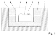
- the energy storage on an electrochemical energy storage device 4 the electrical energy can be supplied, with a portion of this energy is stored in this electrochemical energy storage 4.
- the losses incurred during supply and storage are released as heat.
- This heat then flows through the wall of a pressure vessel, in particular through a housing part 2 of the pressure vessel in a first space with a first material 6. Depending on the heat flow and the heat capacity of the first material, this material then reaches a corresponding temperature.
- the first area is limited by a heat exchanger 1, which is preferably designed flat and is connected to a refrigerator or heat pump. In this way, energy can be recovered from the heat flow and / or the heating of a home can be supplied.
- first and second material earth, sand, gravel and / or another soil material can be used.
- the electrochemical energy storage such as accumulator, battery or the like, containing pressure vessel is composed of a housing part 2 of the pressure vessel and a lid part 3 mounted thereon. It withstands overpressure and in this way improves the protection of the environment in the event of a defect in the electrochemical energy store 4.
- the cover part 3 has an extinguishing agent so that when the cover part 3 is changed or destroyed by, for example, fire, explosion or electrochemical energy storage Chemicals the extinguishing agent, like For example, sand falls on the electrochemical energy storage.
- the cover part 3 can be executed in such a way that already caused by a temperature increase structural change of the cover part 3, in particular melting of the material of the cover part 3, the stored in the lid part 3 extinguishing agent drops through a recess, for example, by the weight of the extinguishing agent in the wall of the Cover part 3 is generated.
- the material of the cover part 3 is plastic or comprises plastic.
- the cover part is designed as a hollow part, wherein the hollow part is filled with sand or other extinguishing agent.
- the weight of the extinguishing agent in particular sand, creates a recess in the wall of the hollow part, so that the extinguishing agent falls onto the energy store 4 and thus cools and / or suffocates the fire.
- the volume of the sand filled into the hollow part is preferably such that after the entire volume of the extinguishing agent has fallen down into the cup-shaped housing part 2, the energy store is covered by the extinguishing agent.
- a protective gas 5 is provided, wherein preferably a fire suffocating gas is used.
- a fire suffocating gas is used.
- a gas whose density at normal pressure is greater than that of ambient temperatures, ie, for example, between -40.degree. C. or -20.degree. C. to + 40.degree.
- carbon dioxide or SF 6 is used, the temperature of the pressure vessel then having to be such that these gases remain gaseous.
- the pressure vessel is waterproof.
- the ingress of water to the electrochemical energy storage and thus caused by oxyhydrogen gas can be prevented.
- a battery or a rechargeable battery can be used, in particular a high-voltage battery, for example with a voltage between 200 volts and 1000 volts.
- the battery is designed as a lithium-ion battery.
- the energy storage is arranged underground, so that the surrounding soil is used for temperature control of the pressure vessel together with energy storage.
- the large heat capacity of the surrounding soil thus causes only small temperature fluctuations on the pressure vessel occur.
- a water-containing mixture for example gravel or sand with water
- a second material soil material, such as earth, sand, gravel or surrounding rock is usable.
- the heat exchanger is designed waterproof and surrounds the first material pot-like, to prevent the flow of water into the second material into it
- thermogenerator instead of the heat exchanger with a connected heat pump or chiller, a thermogenerator is provided, that is arranged between the first material 6 and the second material 7.
- the thermogenerator preferably operates according to a thermoelectric effect, in particular Seebeck effect, so that direct electrical energy can be generated from the temperature difference between the first material 6 and the second material 7.
- the thermogenerator works according to the magnetocaloric effect.
Landscapes
- Chemical & Material Sciences (AREA)
- Chemical Kinetics & Catalysis (AREA)
- Electrochemistry (AREA)
- General Chemical & Material Sciences (AREA)
- Engineering & Computer Science (AREA)
- Manufacturing & Machinery (AREA)
- Health & Medical Sciences (AREA)
- Public Health (AREA)
- Business, Economics & Management (AREA)
- Emergency Management (AREA)
- Battery Mounting, Suspending (AREA)
- Buildings Adapted To Withstand Abnormal External Influences (AREA)
Claims (10)
- Dispositif comportant un accumulateur d'énergie,
l'accumulateur d'énergie, en particulier une batterie, un accumulateur ou analogue, étant disposé dans un boîtier,
la partie couvercle présentant un agent d'extinction, lequel est libéré en cas de déformation, de modification de structure ou de destruction d'origine mécanique ou thermique d'une zone partielle de la partie couvercle et tombe sur l'accumulateur d'énergie,
la zone partielle étant disposée sur la face inférieure de la partie couvercle,
un évidement dans la paroi de la partie couvercle étant produit par la déformation, la modification de structure ou la destruction d'origine mécanique ou thermique,
la partie couvercle étant une partie creuse dans la cavité de laquelle l'agent extincteur est disposé,
caractérisé en ce que
la partie couvercle présente sur sa face supérieure une ouverture obturable permettant de remplir la cavité d'agent extincteur,
un générateur thermoélectrique et/ou un échangeur de chaleur étant disposé à l'extérieur du boîtier, en particulier un premier matériau étant disposé entre le boîtier et le générateur thermoélectrique ou l'échangeur de chaleur et un deuxième matériau étant disposé à l'extérieur du générateur thermoélectrique ou de l'échangeur de chaleur,
le boîtier entourant l'accumulateur d'énergie étant rempli d'un gaz protecteur, en particulier de dioxyde de carbone ou de SF6 ou d'un autre gaz chimiquement inerte, le gaz protecteur présentant dans des conditions normales, en particulier à une pression normale et une température normale ou une température comprise entre -10° Celsius à +50° Celsius, une densité plus élevée que l'oxygène et/ou que l'air,
le boîtier présentant un dispositif de raccordement pour le remplissage avec le gaz protecteur,
la partie couvercle du boîtier étant réalisée en matière plastique. - Dispositif selon la revendication 1,
caractérisé en ce que
le boîtier est disposé enfoui dans le sol et au moins partiellement entouré par du matériau de sol, en particulier donc au moins partiellement entouré par de la terre, du sable, du gravier, des pierres et/ou de l'eau,
et/ou que le boîtier présente une partie couvercle et une partie boîtier en forme de pot sous la forme d'une partie inférieure obturable par la partie couvercle. - Dispositif selon la revendication 1 ou 2,
caractérisé en ce que
l'échangeur de chaleur est relié à une machine frigorifique et/ou une pompe à chaleur au moyen d'une tuyauterie,
le générateur thermoélectrique fonctionnant selon un effet thermoélectrique, en particulier selon l'effet Seebeck ou selon l'effet magnétocalorique,
un premier matériau étant disposé entre le boîtier et le générateur thermoélectrique ou l'échangeur de chaleur et un deuxième matériau étant disposé à l'extérieur du générateur thermoélectrique ou de l'échangeur de chaleur,
le premier matériau présentant une capacité thermique plus élevée que le deuxième matériau. - Dispositif selon au moins l'une des revendications précédentes,
caractérisé en ce que
le boîtier présente une partie couvercle et une partie boîtier, en particulier une partie boîtier en forme de pot, en particulier sous la forme d'une partie inférieure obturable par la partie couvercle. - Dispositif selon au moins l'une des revendications précédentes,
caractérisé en ce que
le boîtier est un récipient sous pression, en particulier qui résiste jusqu'à une surpression critique dans sa zone intérieure. - Dispositif selon au moins l'une des revendications précédentes,
caractérisé en ce que
l'échangeur de chaleur est relié à une machine frigorifique et/ou une pompe à chaleur, en particulier au moyen d'une tuyauterie. - Dispositif selon au moins l'une des revendications précédentes,
caractérisé en ce que
le générateur thermoélectrique fonctionne selon un effet thermoélectrique, en particulier selon l'effet Seebeck ou selon l'effet magnétocalorique. - Dispositif selon la revendication 3,
caractérisé en ce que
le premier matériau présente une capacité thermique plus élevée que le deuxième matériau,
en particulier le premier matériau présentant au moins 20 pour cent en volume d'eau, en particulier le premier matériau présentant au moins 50 pour cent en volume de pierres et/ou de sable. - Dispositif selon la revendication 3,
caractérisé en ce que
le même matériau est utilisé comme premier et deuxième matériau. - Dispositif selon au moins l'une des revendications précédentes,
caractérisé en ce que
l'accumulateur d'énergie présente du lithium et/ou est un accumulateur lithium-ion.
Applications Claiming Priority (2)
| Application Number | Priority Date | Filing Date | Title |
|---|---|---|---|
| DE102011011301 | 2011-02-15 | ||
| PCT/EP2012/000180 WO2012110180A2 (fr) | 2011-02-15 | 2012-01-17 | Dispositif comportant un accumulateur d'énergie |
Publications (2)
| Publication Number | Publication Date |
|---|---|
| EP2676307A2 EP2676307A2 (fr) | 2013-12-25 |
| EP2676307B1 true EP2676307B1 (fr) | 2016-06-29 |
Family
ID=45554612
Family Applications (1)
| Application Number | Title | Priority Date | Filing Date |
|---|---|---|---|
| EP12701441.3A Active EP2676307B1 (fr) | 2011-02-15 | 2012-01-17 | Dispositif comportant un accumulateur d'énergie |
Country Status (3)
| Country | Link |
|---|---|
| EP (1) | EP2676307B1 (fr) |
| DE (1) | DE102012002426A1 (fr) |
| WO (1) | WO2012110180A2 (fr) |
Cited By (1)
| Publication number | Priority date | Publication date | Assignee | Title |
|---|---|---|---|---|
| FR3126263A1 (fr) * | 2021-08-23 | 2023-02-24 | Psa Automobiles Sa | Dispositif de conditionnement et d’entreposage souterrain de stockeurs d’energie electrique |
Families Citing this family (8)
| Publication number | Priority date | Publication date | Assignee | Title |
|---|---|---|---|---|
| DE102013213978A1 (de) * | 2013-07-17 | 2015-01-22 | Siemens Aktiengesellschaft | Abwärmenutzung von Hochtemperaturbatterien |
| DE102013012250A1 (de) * | 2013-07-24 | 2015-01-29 | Envites Energy Gesellschaft für Umwelttechnik und Energiesysteme mbH | Hochleistungs- oder Hohenergiespeicher mit Betriebsraum für elektrische Anlagen mit entgasungsfreien Batterien und Verfahren zur Handhabung einer in einem Betriebsraum angeordneten elektrochemischen Vorrichtung |
| DE102016102969B4 (de) | 2016-02-19 | 2022-03-31 | Thomas Forchert | Anordnung mit einer galvanischen Zelle und gemeinsamer Transportbehälter |
| CN106492376A (zh) * | 2016-12-26 | 2017-03-15 | 无锡中鼎物流设备有限公司 | 一种用于电池库的灭火装置 |
| CN110611141A (zh) * | 2019-09-20 | 2019-12-24 | 国网天津市电力公司电力科学研究院 | 一种适用于在线监测设备电源的热管理装置 |
| CN111467714B (zh) * | 2020-03-24 | 2022-11-25 | 中国电力科学研究院有限公司 | 一种用于电化学储能系统灭火的方法及系统 |
| DE102020133655B3 (de) | 2020-12-16 | 2022-02-03 | Dr. Ing. H.C. F. Porsche Aktiengesellschaft | Kraftfahrzeug-Hochvolt-Komponente |
| CN113230560B (zh) * | 2021-06-03 | 2022-05-20 | 安徽中科久安新能源有限公司 | 一种用于锂离子电化学储能系统灭火防爆的方法 |
Family Cites Families (13)
| Publication number | Priority date | Publication date | Assignee | Title |
|---|---|---|---|---|
| DE3807633A1 (de) * | 1988-03-09 | 1989-09-21 | Schickedanz Willi | Wiederaufladbare batterie |
| US4913985A (en) | 1989-02-21 | 1990-04-03 | Zomeworks Corporation | Battery temperature regulation system |
| DE4230583A1 (de) * | 1992-09-12 | 1994-03-17 | Bayerische Motoren Werke Ag | Elektrische Speicherbatterie, insbesondere für einen Fahrzeug-Antrieb |
| JPH08138638A (ja) * | 1994-11-04 | 1996-05-31 | Shin Kobe Electric Mach Co Ltd | 蓄電池設備 |
| US6006944A (en) * | 1997-08-25 | 1999-12-28 | Machledt; Charles G. | Battery storage vault |
| JP2000030739A (ja) * | 1998-07-15 | 2000-01-28 | Ngk Insulators Ltd | ナトリウム−硫黄電池用真空断熱容器 |
| US6356434B1 (en) * | 1999-04-09 | 2002-03-12 | Thomas A. Osterman | Underground battery vault system for communications applications |
| US6304444B1 (en) * | 1999-08-24 | 2001-10-16 | At&T Corp. | Underground centralized power supply/battery vault |
| JP2001211556A (ja) * | 2000-01-21 | 2001-08-03 | Sekisui Chem Co Ltd | 蓄電システム |
| JP2003007356A (ja) | 2001-06-25 | 2003-01-10 | Matsushita Refrig Co Ltd | 蓄電池の温度調節装置とそれを搭載した移動車 |
| US8096439B2 (en) * | 2007-10-02 | 2012-01-17 | Fogerlie Sivert G | Underground battery container system |
| DE102007050812A1 (de) * | 2007-10-24 | 2009-04-30 | Robert Bosch Gmbh | Elektrochemischer Energiespeicher |
| US20100136402A1 (en) | 2009-04-22 | 2010-06-03 | Tesla Motors, Inc. | Sealed battery enclosure |
-
2012
- 2012-01-17 EP EP12701441.3A patent/EP2676307B1/fr active Active
- 2012-01-17 WO PCT/EP2012/000180 patent/WO2012110180A2/fr not_active Ceased
- 2012-02-09 DE DE201210002426 patent/DE102012002426A1/de active Pending
Non-Patent Citations (1)
| Title |
|---|
| None * |
Cited By (1)
| Publication number | Priority date | Publication date | Assignee | Title |
|---|---|---|---|---|
| FR3126263A1 (fr) * | 2021-08-23 | 2023-02-24 | Psa Automobiles Sa | Dispositif de conditionnement et d’entreposage souterrain de stockeurs d’energie electrique |
Also Published As
| Publication number | Publication date |
|---|---|
| WO2012110180A3 (fr) | 2013-03-07 |
| DE102012002426A1 (de) | 2012-08-16 |
| WO2012110180A2 (fr) | 2012-08-23 |
| EP2676307A2 (fr) | 2013-12-25 |
Similar Documents
| Publication | Publication Date | Title |
|---|---|---|
| EP2676307A2 (fr) | Dispositif comportant un accumulateur d'énergie | |
| EP2815637B1 (fr) | Élément de compensation de pression comprenant une membrane, un boîtier et un module d'éléments de batterie, et véhicule automobile | |
| EP1850445B1 (fr) | Point de chargement de batterie et procédé de fonctionnement et de fabrication correspondant | |
| DE102012214262A1 (de) | Löschkonzept für HV Batterien in Hybrid- und Elektrofahrzeugen | |
| DE102010013033A1 (de) | Vorrichtung zur Kühlung einer Energiespeichereinrichtung | |
| WO2009127396A1 (fr) | Cellule galvanique à protection irréversible | |
| DE202021001906U1 (de) | Lagercontainer für Akkus | |
| EP0588004A1 (fr) | Batterie de stockage d'énergie électrique, en particulier pour l'entraînement d'un véhicule | |
| DE102013012250A1 (de) | Hochleistungs- oder Hohenergiespeicher mit Betriebsraum für elektrische Anlagen mit entgasungsfreien Batterien und Verfahren zur Handhabung einer in einem Betriebsraum angeordneten elektrochemischen Vorrichtung | |
| DE202013010308U1 (de) | Anordnung für sicherere Batterien in Beförderung und Anwendung | |
| DE212022000114U1 (de) | Batteriemodul mit einem Wärmeisolationskissen, das Feuerlöschfunktionen und Kühlfunktionen aufweist, und ein Batteriepack, das dieses Batteriemodul enthält | |
| DE102015000257A1 (de) | Autonome Unterwasserenergieversorgungsvorrichtung | |
| EP4156362A1 (fr) | Système de bloc d'accumulateur pourvu d'au moins deux modules de batterie | |
| US20210242531A1 (en) | Vehicle with a High-Voltage Accumulator | |
| EP3036790B1 (fr) | Système de stockage thermique avec batterie à haute température | |
| DE102009058861A1 (de) | Akkumulatorzelle | |
| DE202023105381U1 (de) | Container für die Lagerung, den Transport, das Aufladen oder die Quarantäne von Hochleistungsbatterien | |
| DE102014220947A1 (de) | Transport- und/oder Lagerbehälter für Batteriekomponenten | |
| DE19614435A1 (de) | Energieversorgungseinheit | |
| EP2574757B1 (fr) | Procédé de fonctionnement d'une centrale d'accumulation d'air comprimé adiabatique et centrale d'accumulation d'air comprimé adiabatique | |
| DE102021123433A1 (de) | Elektronikvorrichtung für ein Kraftfahrzeug sowie Kraftfahrzeug | |
| DE102008048002A1 (de) | Aggregat mit wenigstens einer Funktionszelle sowie Temperaturregeleinrichtung | |
| ITTO20080415A1 (it) | Container per materiali speciali | |
| EP0289907A1 (fr) | Dispositif pour la combustion contrôlée d'un mélange détonable air-hydrogène dans le confinement de réacteurs nucléaires refroidis à l'eau | |
| EP4652642A1 (fr) | Boîtier de protection pour batteries, accumulateurs et piles électriquement rechargeables, et tous moyens de stockage d'énergie électrique |
Legal Events
| Date | Code | Title | Description |
|---|---|---|---|
| PUAI | Public reference made under article 153(3) epc to a published international application that has entered the european phase |
Free format text: ORIGINAL CODE: 0009012 |
|
| 17P | Request for examination filed |
Effective date: 20130916 |
|
| AK | Designated contracting states |
Kind code of ref document: A2 Designated state(s): AL AT BE BG CH CY CZ DE DK EE ES FI FR GB GR HR HU IE IS IT LI LT LU LV MC MK MT NL NO PL PT RO RS SE SI SK SM TR |
|
| DAX | Request for extension of the european patent (deleted) | ||
| 17Q | First examination report despatched |
Effective date: 20140613 |
|
| RIC1 | Information provided on ipc code assigned before grant |
Ipc: A62C 3/16 20060101AFI20160106BHEP Ipc: H01M 10/6572 20140101ALN20160106BHEP Ipc: H01M 2/10 20060101ALI20160106BHEP Ipc: H01M 10/659 20140101ALI20160106BHEP Ipc: A62C 99/00 20100101ALI20160106BHEP Ipc: H01M 10/617 20140101ALI20160106BHEP Ipc: H01M 10/66 20140101ALI20160106BHEP |
|
| REG | Reference to a national code |
Ref country code: DE Ref legal event code: R079 Ref document number: 502012007507 Country of ref document: DE Free format text: PREVIOUS MAIN CLASS: H01M0002100000 Ipc: A62C0003160000 |
|
| GRAP | Despatch of communication of intention to grant a patent |
Free format text: ORIGINAL CODE: EPIDOSNIGR1 |
|
| INTG | Intention to grant announced |
Effective date: 20160224 |
|
| RIC1 | Information provided on ipc code assigned before grant |
Ipc: H01M 10/659 20140101ALI20160216BHEP Ipc: H01M 10/66 20140101ALI20160216BHEP Ipc: H01M 2/10 20060101ALI20160216BHEP Ipc: H01M 10/617 20140101ALI20160216BHEP Ipc: A62C 3/16 20060101AFI20160216BHEP Ipc: A62C 99/00 20100101ALI20160216BHEP Ipc: H01M 10/6572 20140101ALN20160216BHEP |
|
| GRAS | Grant fee paid |
Free format text: ORIGINAL CODE: EPIDOSNIGR3 |
|
| GRAA | (expected) grant |
Free format text: ORIGINAL CODE: 0009210 |
|
| AK | Designated contracting states |
Kind code of ref document: B1 Designated state(s): AL AT BE BG CH CY CZ DE DK EE ES FI FR GB GR HR HU IE IS IT LI LT LU LV MC MK MT NL NO PL PT RO RS SE SI SK SM TR |
|
| REG | Reference to a national code |
Ref country code: GB Ref legal event code: FG4D Free format text: NOT ENGLISH |
|
| REG | Reference to a national code |
Ref country code: CH Ref legal event code: EP |
|
| REG | Reference to a national code |
Ref country code: AT Ref legal event code: REF Ref document number: 808607 Country of ref document: AT Kind code of ref document: T Effective date: 20160715 |
|
| REG | Reference to a national code |
Ref country code: IE Ref legal event code: FG4D Free format text: LANGUAGE OF EP DOCUMENT: GERMAN |
|
| REG | Reference to a national code |
Ref country code: DE Ref legal event code: R096 Ref document number: 502012007507 Country of ref document: DE |
|
| REG | Reference to a national code |
Ref country code: LT Ref legal event code: MG4D |
|
| PG25 | Lapsed in a contracting state [announced via postgrant information from national office to epo] |
Ref country code: NO Free format text: LAPSE BECAUSE OF FAILURE TO SUBMIT A TRANSLATION OF THE DESCRIPTION OR TO PAY THE FEE WITHIN THE PRESCRIBED TIME-LIMIT Effective date: 20160929 Ref country code: FI Free format text: LAPSE BECAUSE OF FAILURE TO SUBMIT A TRANSLATION OF THE DESCRIPTION OR TO PAY THE FEE WITHIN THE PRESCRIBED TIME-LIMIT Effective date: 20160629 Ref country code: LT Free format text: LAPSE BECAUSE OF FAILURE TO SUBMIT A TRANSLATION OF THE DESCRIPTION OR TO PAY THE FEE WITHIN THE PRESCRIBED TIME-LIMIT Effective date: 20160629 |
|
| REG | Reference to a national code |
Ref country code: NL Ref legal event code: MP Effective date: 20160629 |
|
| PG25 | Lapsed in a contracting state [announced via postgrant information from national office to epo] |
Ref country code: SE Free format text: LAPSE BECAUSE OF FAILURE TO SUBMIT A TRANSLATION OF THE DESCRIPTION OR TO PAY THE FEE WITHIN THE PRESCRIBED TIME-LIMIT Effective date: 20160629 Ref country code: LV Free format text: LAPSE BECAUSE OF FAILURE TO SUBMIT A TRANSLATION OF THE DESCRIPTION OR TO PAY THE FEE WITHIN THE PRESCRIBED TIME-LIMIT Effective date: 20160629 Ref country code: RS Free format text: LAPSE BECAUSE OF FAILURE TO SUBMIT A TRANSLATION OF THE DESCRIPTION OR TO PAY THE FEE WITHIN THE PRESCRIBED TIME-LIMIT Effective date: 20160629 Ref country code: GR Free format text: LAPSE BECAUSE OF FAILURE TO SUBMIT A TRANSLATION OF THE DESCRIPTION OR TO PAY THE FEE WITHIN THE PRESCRIBED TIME-LIMIT Effective date: 20160930 Ref country code: HR Free format text: LAPSE BECAUSE OF FAILURE TO SUBMIT A TRANSLATION OF THE DESCRIPTION OR TO PAY THE FEE WITHIN THE PRESCRIBED TIME-LIMIT Effective date: 20160629 Ref country code: NL Free format text: LAPSE BECAUSE OF FAILURE TO SUBMIT A TRANSLATION OF THE DESCRIPTION OR TO PAY THE FEE WITHIN THE PRESCRIBED TIME-LIMIT Effective date: 20160629 |
|
| REG | Reference to a national code |
Ref country code: FR Ref legal event code: PLFP Year of fee payment: 6 |
|
| PG25 | Lapsed in a contracting state [announced via postgrant information from national office to epo] |
Ref country code: IS Free format text: LAPSE BECAUSE OF FAILURE TO SUBMIT A TRANSLATION OF THE DESCRIPTION OR TO PAY THE FEE WITHIN THE PRESCRIBED TIME-LIMIT Effective date: 20161029 Ref country code: SK Free format text: LAPSE BECAUSE OF FAILURE TO SUBMIT A TRANSLATION OF THE DESCRIPTION OR TO PAY THE FEE WITHIN THE PRESCRIBED TIME-LIMIT Effective date: 20160629 Ref country code: RO Free format text: LAPSE BECAUSE OF FAILURE TO SUBMIT A TRANSLATION OF THE DESCRIPTION OR TO PAY THE FEE WITHIN THE PRESCRIBED TIME-LIMIT Effective date: 20160629 Ref country code: EE Free format text: LAPSE BECAUSE OF FAILURE TO SUBMIT A TRANSLATION OF THE DESCRIPTION OR TO PAY THE FEE WITHIN THE PRESCRIBED TIME-LIMIT Effective date: 20160629 Ref country code: CZ Free format text: LAPSE BECAUSE OF FAILURE TO SUBMIT A TRANSLATION OF THE DESCRIPTION OR TO PAY THE FEE WITHIN THE PRESCRIBED TIME-LIMIT Effective date: 20160629 Ref country code: IT Free format text: LAPSE BECAUSE OF FAILURE TO SUBMIT A TRANSLATION OF THE DESCRIPTION OR TO PAY THE FEE WITHIN THE PRESCRIBED TIME-LIMIT Effective date: 20160629 |
|
| PG25 | Lapsed in a contracting state [announced via postgrant information from national office to epo] |
Ref country code: PL Free format text: LAPSE BECAUSE OF FAILURE TO SUBMIT A TRANSLATION OF THE DESCRIPTION OR TO PAY THE FEE WITHIN THE PRESCRIBED TIME-LIMIT Effective date: 20160629 Ref country code: ES Free format text: LAPSE BECAUSE OF FAILURE TO SUBMIT A TRANSLATION OF THE DESCRIPTION OR TO PAY THE FEE WITHIN THE PRESCRIBED TIME-LIMIT Effective date: 20160629 Ref country code: SM Free format text: LAPSE BECAUSE OF FAILURE TO SUBMIT A TRANSLATION OF THE DESCRIPTION OR TO PAY THE FEE WITHIN THE PRESCRIBED TIME-LIMIT Effective date: 20160629 Ref country code: PT Free format text: LAPSE BECAUSE OF FAILURE TO SUBMIT A TRANSLATION OF THE DESCRIPTION OR TO PAY THE FEE WITHIN THE PRESCRIBED TIME-LIMIT Effective date: 20161031 |
|
| REG | Reference to a national code |
Ref country code: DE Ref legal event code: R097 Ref document number: 502012007507 Country of ref document: DE |
|
| PLBE | No opposition filed within time limit |
Free format text: ORIGINAL CODE: 0009261 |
|
| STAA | Information on the status of an ep patent application or granted ep patent |
Free format text: STATUS: NO OPPOSITION FILED WITHIN TIME LIMIT |
|
| PG25 | Lapsed in a contracting state [announced via postgrant information from national office to epo] |
Ref country code: DK Free format text: LAPSE BECAUSE OF FAILURE TO SUBMIT A TRANSLATION OF THE DESCRIPTION OR TO PAY THE FEE WITHIN THE PRESCRIBED TIME-LIMIT Effective date: 20160629 Ref country code: BE Free format text: LAPSE BECAUSE OF NON-PAYMENT OF DUE FEES Effective date: 20170131 |
|
| 26N | No opposition filed |
Effective date: 20170330 |
|
| PG25 | Lapsed in a contracting state [announced via postgrant information from national office to epo] |
Ref country code: BG Free format text: LAPSE BECAUSE OF FAILURE TO SUBMIT A TRANSLATION OF THE DESCRIPTION OR TO PAY THE FEE WITHIN THE PRESCRIBED TIME-LIMIT Effective date: 20160929 Ref country code: SI Free format text: LAPSE BECAUSE OF FAILURE TO SUBMIT A TRANSLATION OF THE DESCRIPTION OR TO PAY THE FEE WITHIN THE PRESCRIBED TIME-LIMIT Effective date: 20160629 |
|
| REG | Reference to a national code |
Ref country code: CH Ref legal event code: PL |
|
| PG25 | Lapsed in a contracting state [announced via postgrant information from national office to epo] |
Ref country code: MC Free format text: LAPSE BECAUSE OF FAILURE TO SUBMIT A TRANSLATION OF THE DESCRIPTION OR TO PAY THE FEE WITHIN THE PRESCRIBED TIME-LIMIT Effective date: 20160629 |
|
| PG25 | Lapsed in a contracting state [announced via postgrant information from national office to epo] |
Ref country code: CH Free format text: LAPSE BECAUSE OF NON-PAYMENT OF DUE FEES Effective date: 20170131 Ref country code: LI Free format text: LAPSE BECAUSE OF NON-PAYMENT OF DUE FEES Effective date: 20170131 |
|
| REG | Reference to a national code |
Ref country code: IE Ref legal event code: MM4A |
|
| PG25 | Lapsed in a contracting state [announced via postgrant information from national office to epo] |
Ref country code: LU Free format text: LAPSE BECAUSE OF NON-PAYMENT OF DUE FEES Effective date: 20170117 |
|
| REG | Reference to a national code |
Ref country code: FR Ref legal event code: PLFP Year of fee payment: 7 |
|
| REG | Reference to a national code |
Ref country code: BE Ref legal event code: MM Effective date: 20170131 |
|
| PG25 | Lapsed in a contracting state [announced via postgrant information from national office to epo] |
Ref country code: IE Free format text: LAPSE BECAUSE OF NON-PAYMENT OF DUE FEES Effective date: 20170117 |
|
| REG | Reference to a national code |
Ref country code: AT Ref legal event code: MM01 Ref document number: 808607 Country of ref document: AT Kind code of ref document: T Effective date: 20170117 |
|
| PG25 | Lapsed in a contracting state [announced via postgrant information from national office to epo] |
Ref country code: AT Free format text: LAPSE BECAUSE OF NON-PAYMENT OF DUE FEES Effective date: 20170117 |
|
| PG25 | Lapsed in a contracting state [announced via postgrant information from national office to epo] |
Ref country code: MT Free format text: LAPSE BECAUSE OF FAILURE TO SUBMIT A TRANSLATION OF THE DESCRIPTION OR TO PAY THE FEE WITHIN THE PRESCRIBED TIME-LIMIT Effective date: 20160629 |
|
| PG25 | Lapsed in a contracting state [announced via postgrant information from national office to epo] |
Ref country code: AL Free format text: LAPSE BECAUSE OF FAILURE TO SUBMIT A TRANSLATION OF THE DESCRIPTION OR TO PAY THE FEE WITHIN THE PRESCRIBED TIME-LIMIT Effective date: 20160629 |
|
| PG25 | Lapsed in a contracting state [announced via postgrant information from national office to epo] |
Ref country code: HU Free format text: LAPSE BECAUSE OF FAILURE TO SUBMIT A TRANSLATION OF THE DESCRIPTION OR TO PAY THE FEE WITHIN THE PRESCRIBED TIME-LIMIT; INVALID AB INITIO Effective date: 20120117 |
|
| PG25 | Lapsed in a contracting state [announced via postgrant information from national office to epo] |
Ref country code: CY Free format text: LAPSE BECAUSE OF NON-PAYMENT OF DUE FEES Effective date: 20160629 |
|
| PG25 | Lapsed in a contracting state [announced via postgrant information from national office to epo] |
Ref country code: MK Free format text: LAPSE BECAUSE OF FAILURE TO SUBMIT A TRANSLATION OF THE DESCRIPTION OR TO PAY THE FEE WITHIN THE PRESCRIBED TIME-LIMIT Effective date: 20160629 |
|
| PG25 | Lapsed in a contracting state [announced via postgrant information from national office to epo] |
Ref country code: TR Free format text: LAPSE BECAUSE OF FAILURE TO SUBMIT A TRANSLATION OF THE DESCRIPTION OR TO PAY THE FEE WITHIN THE PRESCRIBED TIME-LIMIT Effective date: 20160629 |
|
| PGFP | Annual fee paid to national office [announced via postgrant information from national office to epo] |
Ref country code: GB Payment date: 20251204 Year of fee payment: 15 |
|
| PGFP | Annual fee paid to national office [announced via postgrant information from national office to epo] |
Ref country code: FR Payment date: 20251208 Year of fee payment: 15 |
|
| REG | Reference to a national code |
Ref country code: DE Ref legal event code: R084 Ref document number: 502012007507 Country of ref document: DE |
|
| PGFP | Annual fee paid to national office [announced via postgrant information from national office to epo] |
Ref country code: DE Payment date: 20260131 Year of fee payment: 15 |