EP2676558A1 - Dispositif de séparation d'un faisceau acheminé sans fin d'un produit de l'industrie de traitement du tabac en tiges individuelles - Google Patents
Dispositif de séparation d'un faisceau acheminé sans fin d'un produit de l'industrie de traitement du tabac en tiges individuelles Download PDFInfo
- Publication number
- EP2676558A1 EP2676558A1 EP13171204.4A EP13171204A EP2676558A1 EP 2676558 A1 EP2676558 A1 EP 2676558A1 EP 13171204 A EP13171204 A EP 13171204A EP 2676558 A1 EP2676558 A1 EP 2676558A1
- Authority
- EP
- European Patent Office
- Prior art keywords
- mounting position
- tubenradbaugruppe
- clamping
- movement
- strand
- Prior art date
- Legal status (The legal status is an assumption and is not a legal conclusion. Google has not performed a legal analysis and makes no representation as to the accuracy of the status listed.)
- Granted
Links
Images

Classifications
-
- A—HUMAN NECESSITIES
- A24—TOBACCO; CIGARS; CIGARETTES; SIMULATED SMOKING DEVICES; SMOKERS' REQUISITES
- A24C—MACHINES FOR MAKING CIGARS OR CIGARETTES
- A24C5/00—Making cigarettes; Making tipping materials for, or attaching filters or mouthpieces to, cigars or cigarettes
- A24C5/14—Machines of the continuous-rod type
- A24C5/28—Cutting-off the tobacco rod
Definitions
- Such a device is for example from the DE 10 2008 016 958 A1 known.
- a problem of the aforementioned device is that the contact surfaces of the guide parts must be adapted to the individual diameter of the strand, so that they can be used only for separating products of a certain diameter.
- the rod length of the severed rods is predetermined by the number of guide members, the diameter on which the guide members rotate, and the rotational speed of the tube wheel, it may be necessary for economic or process-related reasons to use a tube wheel of a different diameter or number use of leadership parts when products with another Rod length to be produced.
- the conversion to the production of products with different diameter and / or different rod length is also called format change.
- the Tubenrad is replaced together with the cooperating with the Tubenrad parts as Tubenradbaueria, including a number of screws solved the Tubenradbauuite exchanged and then attached a new Tubenradbauè again by screwing the screws and must be aligned consuming.
- This entire change process is relatively expensive and requires some practice. Overall, the change process takes between 15 minutes and 30 minutes, during which the entire device must be shut down, so that this time must be considered a loss of production.
- the object of the invention is to provide a generic device in which the change process of the Tubenradbau devise is simplified and in particular can be carried out in a shorter time.
- the device has at least one tensioning device which brings the Tubenradbauè in an activation from a desired mounting position in a mounting position and vice versa.
- the advantage of the proposed solution is the fact that the Tubenradbautik no longer solved manually attached and must be aligned, but instead only brought into the assembly position or must be removed from this, which can be done without tools.
- the movement out of the tightly tolerated nominal fastening position and back into it is instead effected by means of the tensioning device, which only needs to be activated for this purpose. Since the movement caused by the tensioning mechanism is triggered by the activation of the tensioning device practically automatically and also caused by controlled cooperating parts, the Tubenrad is brought much faster and more accurate in the desired mounting position or brought out of this than with the previously in the state of Technique used manual assembly was possible.
- the Tubenradbau devise can be changed without further knowledge or skill of the operator, since the Tubenradbaue is automatically brought in an activation of the tensioning device in the target mounting position or moved out of this.
- the target fastening position is the position in which the individual parts of the Tubenradbauage take their desired position to a drive unit in the device, ie, the items are in a position to each other in which the Tubenrad can be driven.
- the mounting position is the position in which the operator must bring the Tubenradbauè so that the clamping device engages the cooperating with these components of the Tubenradbauè and finally brings by performing a tensioning movement in the desired mounting position.
- the disassembly and assembly of the Tubenradbaueria each in two steps, namely bringing the Tubenradbauè in the mounting position and the movement from the mounting position into the desired mounting position and vice versa, be divided.
- the proposed solution is particularly against the background of the shortest possible changeover time of the device and thereby made possible short production downtime during a format change of particular importance.
- the attachment position and the mounting position can be very close to each other, or even be almost identical, provided that the Tubenradbau devise example, executes a trackless tensioning movement.
- the Tubenradbau devis is anticipated in the mounting position by means of a guide and / or a centering, and during movement into the desired mounting position on the guiding and / or centering surface is guided in the target mounting position movable.
- the movement can be performed with a very high accuracy in a very short time, in particular it can be ensured that the drive shaft of the tube wheel in the desired mounting position has a predetermined centered alignment with the device and a drive unit disposed therein.
- the Tubenradbautik can be coupled via a coupling to the device, which has two coupling parts which align themselves automatically during movement from the mounting position to the desired mounting position to each other.
- the tube wheel assembly with the drive shaft can be coupled to the device and in particular to a drive unit provided there so that the tube wheel can then be driven by the drive unit without further handling steps.
- the coupling parts are biased against each other in the desired mounting position without play.
- the play-free bias can be ensured that the rotational movement is transmitted without slipping.
- the bias of the coupling parts at the same time the effect of an automatic release of the coupling parts upon actuation of the clamping device for releasing the Tubenradbautik. Since the coupling parts are the decisive components to be detached from one another in the path of movement from the drive unit to the tube wheel, the reliable release of these components is particularly important for disassembling the tube wheel assembly.
- the coupling parts are biased both axially and radially against each other, so that both coupling parts are fixed in position in both directions.
- the Tubenradbaue is spring-loaded in the direction of the mounting position.
- the release movement of the Tubenradbaue be further simplified by an excavation of the entire Tubenradbaue upon actuation of the tensioning device, the excavation direction and thus the direction of the release movement can be practically dictated by the direction of the bias.
- the Tubenradbau devise comprises a drive shaft, and the movement from the target mounting position is aligned in the mounting position and vice versa parallel to the axis of the drive shaft.
- the proposed alignment of the movement of the structural design of the Tubenradbaueria can be made very simple, the Tubenradbaueria thereby also can be moved particularly easily with the drive shaft in the centered position.
- the clamping device has at least one clamping cylinder and at least one clamping pin, and the movement of the Tubenradbaueria from the target mounting position is aligned in the mounting position in the direction of the longitudinal axis of the clamping pin.
- the proposed alignment of the movement, the structure of the Tubenradbaueria can be simplified and the clamping movement structurally particularly easy to implement.
- the Tubenradbauen is arranged via a spigot on the device and is fixed in rotation by at least one introduced into the clamping cylinder clamping pin.
- the centering approach is used in this case for the centric alignment of the Tubenradbauè and in particular the drive shaft provided therein to the device and the drive unit provided therein.
- the clamping pins then serve to fix the Tubenradbauuite non-rotatable, so that the Tubenradbauen is moved in a clearly defined orientation in the desired mounting position.
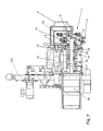
- a device according to the invention with a frame 100 and a Tubenradbauffle 1 arranged thereon can be seen from the front.
- a non-illustrated rotary blade carrier is provided below the Tubenradbauxx 1, which separates the rod-shaped products of one or more parallel fed endless strands in a predetermined length.
- the Tubenradbau devis 1 comprises as a central component rotatably driven Tubenrad 4 with a plurality of guide members 7, which have a plane substantially perpendicular to the plane of representation.
- the rotational movement of the tube wheel 4 is so coupled with the rotational movement of the rotating blade carrier that the guide members 7 at a time pass through the lower reversal point while supporting the strand to which a knife of the knife carrier at the same time passes through the slot of the guide member 7 and the product separated from the endless strand.
- the guide member 7 acts during the cutting movement as an abutment and prevents the strand is moved away from the side of the knife.
- the synchronization of the rotational movement of the Tubenrades 4 and the knife carrier can be done either by a common drive and a transmission or by two separate drive means with a corresponding control.
- the Tubenradbauxx 1 with the associated unrecognizable drive is movable as an assembly and with the drive unit via a drive device 3 with a lever connection in height. Furthermore, a handle 2 and two clamping pins 5 and 6 can be seen, whose function will be described later.
- the Tubenradbaury 1 includes in Substantially following components: a drive shaft 14 with a first coupling half 16, the tube wheel 4 with the guide parts 7 arranged thereon, a bearing unit 22, a rotatably mounted mating gear 10 with a number of guide parts 7 corresponding number of coupling 8, three clamping pins 13, 5th and 6 (s. Fig.1 These are the components which are required in cooperation in the movement from the first coupling half 16 to the guide parts 7, including the holding frame 11 for holding the components and the handle 2 for handling the Tubenradbauuite. 1 ,
- a drive unit 18 is further provided with a second coupling part 17 and a clamping cylinder 12.
- a second coupling part 17 On the frame 100, a drive unit 18 is further provided with a second coupling part 17 and a clamping cylinder 12.
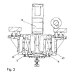
- a clamping cylinder 12 In the Fig. 3 , Which represents the view in the cutting direction BB, two more clamping cylinders 19 and 20 with the clamping pins 5 and 6 can be seen.
- the task of the clamping cylinder 12,19 and 20 is to keep the clamping pins 5,6 and 13 and thus the entire Tubenradbauuite 1 on the frame 100, in a predefined, in the Fig. 2 shown Sollbefest Trentsdian I.
- the clamping cylinder 12,19 and 20 together with the clamping pins 5,6 and 13 an externally controllable clamping device.
- the Tubenradbauxx 1 is in the target mounting position I in such an arrangement that the first coupling half 16 and the drive shaft 14 to the drive unit 18 and the second coupling half 17 are centered, and the two coupling halves 16 and 17 are biased backlash to each other.
- the drive unit 18 drives the drive shaft 14 and the tube wheel 4 in this position via the engaged Coupling halves 16 and 17 on activation at a rotational.
- the mating gear 10 is mounted eccentrically to the drive shaft 14 and enforces via the coupling 8 a constant alignment of the rotatably mounted on the tube wheel 4 guide parts. 7
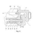
- the clamping device is activated, ie the clamping cylinder 12,19 and 20 are actuated and the clamping pins 5,6 and 13 thereby expelled, so that the entire Tubenradbauè 1 from the in the Fig. 2 shown Sollbefest Trentswolf I in the in the Fig. 4 shown mounting position II is moved.
- the clamping pins 13,5 and 6 are still in the clamping cylinders 12,19 or 20 and a spigot 15 still protrudes a short distance in a corresponding centering 21.
- the entire Tubenradbauzy 1 can then by the operator by gripping the handle 2 are pulled out.
- the assembly process of the new Tubenradbauuite 1 with another Tubenrad 4 takes place in the reverse order by the new Tubenradbaury 1 is first moved to the mounting position II.
- the mounting position II can be found very easily by the clamping pins 5,6 and 13 in the clamping cylinder 12,19 and 20 and the spigot 15 is inserted into the centering 21. This discovery process is the only handling operation that requires a certain skill of the operator, but it can still be done entirely without tools.
- the spigot 15 is of particular importance, since it is both to the drive shaft 14 as well as to the bearing unit 22 is arranged centrally and by the positioning in the centering 21 also a centric alignment of the bearing unit 21 to the bearing receptacle 23 in the frame 100 and the holding frame 11 and a centric alignment of the first coupling half 16 to the second coupling half 17 allows.
- the clamping device After finding the mounting position II, the clamping device is activated, whereby the clamping cylinder 12,19 and 20 in an automated process, the clamping pins 5,6 and 13 engage and the Tubenradbauuite 1 in the in the Fig. 2 to draw to recognize target mounting position I, the movement is guided by the voltage applied in the centering 21 centering lug 15, the voltage applied to the bearing seat 23 bearing unit 22 and the intermeshing coupling halves 16 and 17.
- the intermeshing coupling halves 16 and 17 can align themselves by performing a slight rotational movement to each other.
- the coupling halves 16 and 17 are biased against each other without play by one of the coupling halves 16 or 17 is spring-loaded accordingly.
- the clamping cylinders 12,19 and 20 have clamping jaws, not shown, which engage the chuck 5.6 13 and force the movement.
- the movement is forced through conical sliding surfaces and blocked in the end positions via self-locking clamping elements.
- the desired fastening position I is characterized in that the coupling halves 16 and 17 are arranged relative to one another and thus also the drive shaft 14 to the drive unit 18 in an operative orientation to each other.
- the entire unit of the Tubenradbauxx 1 and the drive unit 18 can then of course still be moved as a composite on the drive means 3 in height, so that the guide members 7 are arranged in the lowest reversal point in which they support the strand at the correct height.
- the mounting position I is only to be regarded as a kind of pre-position, from which the clamping device the Tubenradlini 1 then automatically and under guidance on the centering and guide surfaces, such as the centering 21 and the bearing seat 23, moves into the desired mounting position I upon activation.
- the movement is performed in the clamping device itself, for example in a guided movement of provided in the jig collets. In any case, finding the set fixing position I is not subject more the expertise and skill of the operator.
- the clamping cylinders 12, 19 and 20 may be e.g. be electrically, hydraulically or pneumatically actuated, wherein an electrical operation has the advantage of a particularly good and fine controllability.
- the coupling halves 16 and 17 are shaped so that they automatically align during the movement from the assembly position II to the target fastening position I, which is e.g. can be realized by a narrowing in the direction of the feed movement recess in the second coupling half 17 and a correspondingly shaped approach to the first coupling half 16.
Landscapes
- Clamps And Clips (AREA)
- Automatic Assembly (AREA)
- Jigs For Machine Tools (AREA)
Priority Applications (1)
| Application Number | Priority Date | Filing Date | Title |
|---|---|---|---|
| PL13171204T PL2676558T3 (pl) | 2012-06-18 | 2013-06-10 | Urządzenie do rozdzielania na pojedyncze pałeczki doprowadzonego ciągłego pasma produktu w przemyśle przetwórstwa tytoniu |
Applications Claiming Priority (1)
| Application Number | Priority Date | Filing Date | Title |
|---|---|---|---|
| DE102012210228A DE102012210228A1 (de) | 2012-06-18 | 2012-06-18 | Vorrichtung zum Trennen eines endlosen zugeführten Stranges eines Produktes der Tabak verarbeitenden Industrie in einzelne Stäbe |
Publications (2)
| Publication Number | Publication Date |
|---|---|
| EP2676558A1 true EP2676558A1 (fr) | 2013-12-25 |
| EP2676558B1 EP2676558B1 (fr) | 2017-10-25 |
Family
ID=48613462
Family Applications (1)
| Application Number | Title | Priority Date | Filing Date |
|---|---|---|---|
| EP13171204.4A Active EP2676558B1 (fr) | 2012-06-18 | 2013-06-10 | Dispositif de séparation d'un faisceau acheminé sans fin d'un produit de l'industrie de traitement du tabac en tiges individuelles |
Country Status (4)
| Country | Link |
|---|---|
| EP (1) | EP2676558B1 (fr) |
| CN (1) | CN103504468B (fr) |
| DE (1) | DE102012210228A1 (fr) |
| PL (1) | PL2676558T3 (fr) |
Cited By (2)
| Publication number | Priority date | Publication date | Assignee | Title |
|---|---|---|---|---|
| CN104690508A (zh) * | 2015-02-10 | 2015-06-10 | 广东中烟工业有限责任公司 | 一种进刀顶杆的制造方法 |
| WO2017203415A1 (fr) | 2016-05-26 | 2017-11-30 | G.D S.P.A. | Dispositif pour changer des parties fonctionnelles de machines de l'industrie du tabac |
Citations (5)
| Publication number | Priority date | Publication date | Assignee | Title |
|---|---|---|---|---|
| EP1532879A1 (fr) * | 2003-11-19 | 2005-05-25 | G.D Societ Per Azioni | Tambour perfectionné pour machines pour la production de cigarettes à filtre |
| EP1815757A1 (fr) * | 2006-02-02 | 2007-08-08 | G.D.S.p.A. | Dispositif de découpe pour produits de tabac |
| EP1905316A2 (fr) * | 2006-09-28 | 2008-04-02 | G.D Societ Per Azioni | Unité de découpage pour couper au moins une tige continue |
| DE102008016958A1 (de) | 2008-03-31 | 2009-10-01 | Hauni Maschinenbau Ag | Vorrichtung zum Führen und Halten in Transportrichtung T kontinuierlich geförderter, strangförmiger Artikel, Verfahren zum Anpassen einer solchen Vorrichtung an unterschiedliche Schnittlängen sowie Tubenradsatz |
| EP2258220A1 (fr) * | 2009-06-06 | 2010-12-08 | Hauni Maschinenbau AG | Dispositif de coupe de l'industrie de traitement du tabac destiné à couper au moins un faisceau transporté en une multitude d'articles en forme de tiges ainsi que procédé de mise en marche extérieure du dispositif de coupe |
Family Cites Families (2)
| Publication number | Priority date | Publication date | Assignee | Title |
|---|---|---|---|---|
| ITBO20030692A1 (it) * | 2003-11-19 | 2005-05-20 | Gd Spa | Unita' di taglio per bachi continui di sigaretta. |
| DE102009022756A1 (de) * | 2009-05-26 | 2010-12-02 | Hauni Maschinenbau Ag | Schneidtube |
-
2012
- 2012-06-18 DE DE102012210228A patent/DE102012210228A1/de not_active Ceased
-
2013
- 2013-06-10 PL PL13171204T patent/PL2676558T3/pl unknown
- 2013-06-10 EP EP13171204.4A patent/EP2676558B1/fr active Active
- 2013-06-17 CN CN201310238319.3A patent/CN103504468B/zh active Active
Patent Citations (5)
| Publication number | Priority date | Publication date | Assignee | Title |
|---|---|---|---|---|
| EP1532879A1 (fr) * | 2003-11-19 | 2005-05-25 | G.D Societ Per Azioni | Tambour perfectionné pour machines pour la production de cigarettes à filtre |
| EP1815757A1 (fr) * | 2006-02-02 | 2007-08-08 | G.D.S.p.A. | Dispositif de découpe pour produits de tabac |
| EP1905316A2 (fr) * | 2006-09-28 | 2008-04-02 | G.D Societ Per Azioni | Unité de découpage pour couper au moins une tige continue |
| DE102008016958A1 (de) | 2008-03-31 | 2009-10-01 | Hauni Maschinenbau Ag | Vorrichtung zum Führen und Halten in Transportrichtung T kontinuierlich geförderter, strangförmiger Artikel, Verfahren zum Anpassen einer solchen Vorrichtung an unterschiedliche Schnittlängen sowie Tubenradsatz |
| EP2258220A1 (fr) * | 2009-06-06 | 2010-12-08 | Hauni Maschinenbau AG | Dispositif de coupe de l'industrie de traitement du tabac destiné à couper au moins un faisceau transporté en une multitude d'articles en forme de tiges ainsi que procédé de mise en marche extérieure du dispositif de coupe |
Cited By (3)
| Publication number | Priority date | Publication date | Assignee | Title |
|---|---|---|---|---|
| CN104690508A (zh) * | 2015-02-10 | 2015-06-10 | 广东中烟工业有限责任公司 | 一种进刀顶杆的制造方法 |
| WO2017203415A1 (fr) | 2016-05-26 | 2017-11-30 | G.D S.P.A. | Dispositif pour changer des parties fonctionnelles de machines de l'industrie du tabac |
| EP3462924B1 (fr) * | 2016-05-26 | 2024-07-24 | G.D S.p.A. | Dispositif pour changer des parties fonctionnelles de machines de l'industrie du tabac |
Also Published As
| Publication number | Publication date |
|---|---|
| PL2676558T3 (pl) | 2018-04-30 |
| DE102012210228A9 (de) | 2014-03-13 |
| CN103504468B (zh) | 2017-05-03 |
| CN103504468A (zh) | 2014-01-15 |
| EP2676558B1 (fr) | 2017-10-25 |
| DE102012210228A1 (de) | 2013-12-19 |
Similar Documents
| Publication | Publication Date | Title |
|---|---|---|
| DE2213779C3 (de) | Vorrichtung für die Demontage und Montage von Reifen auf Felgen | |
| EP0079587B1 (fr) | Machine à plier des fils | |
| EP3676186B1 (fr) | Dispositif à porte-plaque à changement rapide et came de guidage coulissante | |
| DE4234115A1 (de) | Dosenverschliessmaschine | |
| EP2845714A1 (fr) | Dispositif et procédé destinés au chauffage d'ébauches en plastique avec montage ou démontage simultané d'éléments de chauffage et d'éléments de blindage | |
| DE102015109791A1 (de) | Schraubvorrichtung zum Eindrehen von Schrauben | |
| EP0623421A1 (fr) | Dispositif pour le formage unilatéral de pièces tubulaires de différents diamètres | |
| EP1640125A1 (fr) | Procédé et dispositif pour couper une tige guidée continûment dans des articles en forme de tige | |
| DE3023185A1 (de) | Werkzeugmaschine mit hohler hauptspindel und einer materialstab-vorschubeinrichtung | |
| EP2676558B1 (fr) | Dispositif de séparation d'un faisceau acheminé sans fin d'un produit de l'industrie de traitement du tabac en tiges individuelles | |
| DE3804502C2 (fr) | ||
| EP3560668A1 (fr) | Dispositif et procédé de coupe de produits, en particulier d'une masse de confiserie | |
| EP3456443B1 (fr) | Dispositif d'alimentation en matériau en barres | |
| DE3710829A1 (de) | Vorrichtung zum montieren von dichtungsringen | |
| WO2019145203A1 (fr) | Dispositif de maintien destiné à maintenir des volailles abattues évidées ou des parties de ces dernières pendant le traitement dans un dispositif destiné au traitement de volailles abattues évidées ou de parties de ces dernières | |
| EP2574246B1 (fr) | Dispositif de fabrication de filtres pour l'industrie de traitement du tabac | |
| EP1331061A1 (fr) | Dispositif de serrage | |
| EP3600712B1 (fr) | Installation de dressage de fils et procédé pour le dressage de fils au moyen de l'installation de dressage de fils | |
| EP2420350A2 (fr) | Dispositif d'avance et machine, notamment machine à écorcer | |
| EP3511460B1 (fr) | Métier à tricoter à chaîne et procédé d'assistance à l'utilisateur pour métier à tricoter à chaîne | |
| DE102011015578A1 (de) | Buchsenausrichtvorrichtung für Stangenlademagazine und Verfahren | |
| DE2313485C3 (de) | Spannfutter | |
| DE4207113C2 (de) | Vorrichtung zum Positionieren und Halten von Werkstücken | |
| DE10343378B4 (de) | Vorrichtung zum Bearbeiten von Werkstücken an einer Anzahl von Arbeitsstationen | |
| DE112016004182B4 (de) | Verfahren zum Montieren von Gewindeeinsätzen |
Legal Events
| Date | Code | Title | Description |
|---|---|---|---|
| PUAI | Public reference made under article 153(3) epc to a published international application that has entered the european phase |
Free format text: ORIGINAL CODE: 0009012 |
|
| AK | Designated contracting states |
Kind code of ref document: A1 Designated state(s): AL AT BE BG CH CY CZ DE DK EE ES FI FR GB GR HR HU IE IS IT LI LT LU LV MC MK MT NL NO PL PT RO RS SE SI SK SM TR |
|
| AX | Request for extension of the european patent |
Extension state: BA ME |
|
| 17P | Request for examination filed |
Effective date: 20140305 |
|
| RBV | Designated contracting states (corrected) |
Designated state(s): AL AT BE BG CH CY CZ DE DK EE ES FI FR GB GR HR HU IE IS IT LI LT LU LV MC MK MT NL NO PL PT RO RS SE SI SK SM TR |
|
| RAP1 | Party data changed (applicant data changed or rights of an application transferred) |
Owner name: HAUNI MASCHINENBAU GMBH |
|
| GRAP | Despatch of communication of intention to grant a patent |
Free format text: ORIGINAL CODE: EPIDOSNIGR1 |
|
| INTG | Intention to grant announced |
Effective date: 20170612 |
|
| GRAS | Grant fee paid |
Free format text: ORIGINAL CODE: EPIDOSNIGR3 |
|
| GRAA | (expected) grant |
Free format text: ORIGINAL CODE: 0009210 |
|
| AK | Designated contracting states |
Kind code of ref document: B1 Designated state(s): AL AT BE BG CH CY CZ DE DK EE ES FI FR GB GR HR HU IE IS IT LI LT LU LV MC MK MT NL NO PL PT RO RS SE SI SK SM TR |
|
| REG | Reference to a national code |
Ref country code: GB Ref legal event code: FG4D Free format text: NOT ENGLISH |
|
| REG | Reference to a national code |
Ref country code: CH Ref legal event code: EP |
|
| REG | Reference to a national code |
Ref country code: AT Ref legal event code: REF Ref document number: 939021 Country of ref document: AT Kind code of ref document: T Effective date: 20171115 |
|
| REG | Reference to a national code |
Ref country code: IE Ref legal event code: FG4D Free format text: LANGUAGE OF EP DOCUMENT: GERMAN |
|
| REG | Reference to a national code |
Ref country code: DE Ref legal event code: R096 Ref document number: 502013008636 Country of ref document: DE |
|
| REG | Reference to a national code |
Ref country code: NL Ref legal event code: FP |
|
| REG | Reference to a national code |
Ref country code: LT Ref legal event code: MG4D |
|
| PG25 | Lapsed in a contracting state [announced via postgrant information from national office to epo] |
Ref country code: SE Free format text: LAPSE BECAUSE OF FAILURE TO SUBMIT A TRANSLATION OF THE DESCRIPTION OR TO PAY THE FEE WITHIN THE PRESCRIBED TIME-LIMIT Effective date: 20171025 Ref country code: ES Free format text: LAPSE BECAUSE OF FAILURE TO SUBMIT A TRANSLATION OF THE DESCRIPTION OR TO PAY THE FEE WITHIN THE PRESCRIBED TIME-LIMIT Effective date: 20171025 Ref country code: NO Free format text: LAPSE BECAUSE OF FAILURE TO SUBMIT A TRANSLATION OF THE DESCRIPTION OR TO PAY THE FEE WITHIN THE PRESCRIBED TIME-LIMIT Effective date: 20180125 Ref country code: FI Free format text: LAPSE BECAUSE OF FAILURE TO SUBMIT A TRANSLATION OF THE DESCRIPTION OR TO PAY THE FEE WITHIN THE PRESCRIBED TIME-LIMIT Effective date: 20171025 Ref country code: LT Free format text: LAPSE BECAUSE OF FAILURE TO SUBMIT A TRANSLATION OF THE DESCRIPTION OR TO PAY THE FEE WITHIN THE PRESCRIBED TIME-LIMIT Effective date: 20171025 |
|
| PG25 | Lapsed in a contracting state [announced via postgrant information from national office to epo] |
Ref country code: LV Free format text: LAPSE BECAUSE OF FAILURE TO SUBMIT A TRANSLATION OF THE DESCRIPTION OR TO PAY THE FEE WITHIN THE PRESCRIBED TIME-LIMIT Effective date: 20171025 Ref country code: RS Free format text: LAPSE BECAUSE OF FAILURE TO SUBMIT A TRANSLATION OF THE DESCRIPTION OR TO PAY THE FEE WITHIN THE PRESCRIBED TIME-LIMIT Effective date: 20171025 Ref country code: GR Free format text: LAPSE BECAUSE OF FAILURE TO SUBMIT A TRANSLATION OF THE DESCRIPTION OR TO PAY THE FEE WITHIN THE PRESCRIBED TIME-LIMIT Effective date: 20180126 Ref country code: IS Free format text: LAPSE BECAUSE OF FAILURE TO SUBMIT A TRANSLATION OF THE DESCRIPTION OR TO PAY THE FEE WITHIN THE PRESCRIBED TIME-LIMIT Effective date: 20180225 Ref country code: BG Free format text: LAPSE BECAUSE OF FAILURE TO SUBMIT A TRANSLATION OF THE DESCRIPTION OR TO PAY THE FEE WITHIN THE PRESCRIBED TIME-LIMIT Effective date: 20180125 Ref country code: HR Free format text: LAPSE BECAUSE OF FAILURE TO SUBMIT A TRANSLATION OF THE DESCRIPTION OR TO PAY THE FEE WITHIN THE PRESCRIBED TIME-LIMIT Effective date: 20171025 |
|
| REG | Reference to a national code |
Ref country code: DE Ref legal event code: R097 Ref document number: 502013008636 Country of ref document: DE |
|
| PG25 | Lapsed in a contracting state [announced via postgrant information from national office to epo] |
Ref country code: CY Free format text: LAPSE BECAUSE OF FAILURE TO SUBMIT A TRANSLATION OF THE DESCRIPTION OR TO PAY THE FEE WITHIN THE PRESCRIBED TIME-LIMIT Effective date: 20171025 Ref country code: EE Free format text: LAPSE BECAUSE OF FAILURE TO SUBMIT A TRANSLATION OF THE DESCRIPTION OR TO PAY THE FEE WITHIN THE PRESCRIBED TIME-LIMIT Effective date: 20171025 Ref country code: DK Free format text: LAPSE BECAUSE OF FAILURE TO SUBMIT A TRANSLATION OF THE DESCRIPTION OR TO PAY THE FEE WITHIN THE PRESCRIBED TIME-LIMIT Effective date: 20171025 Ref country code: SK Free format text: LAPSE BECAUSE OF FAILURE TO SUBMIT A TRANSLATION OF THE DESCRIPTION OR TO PAY THE FEE WITHIN THE PRESCRIBED TIME-LIMIT Effective date: 20171025 Ref country code: CZ Free format text: LAPSE BECAUSE OF FAILURE TO SUBMIT A TRANSLATION OF THE DESCRIPTION OR TO PAY THE FEE WITHIN THE PRESCRIBED TIME-LIMIT Effective date: 20171025 |
|
| PG25 | Lapsed in a contracting state [announced via postgrant information from national office to epo] |
Ref country code: SM Free format text: LAPSE BECAUSE OF FAILURE TO SUBMIT A TRANSLATION OF THE DESCRIPTION OR TO PAY THE FEE WITHIN THE PRESCRIBED TIME-LIMIT Effective date: 20171025 Ref country code: RO Free format text: LAPSE BECAUSE OF FAILURE TO SUBMIT A TRANSLATION OF THE DESCRIPTION OR TO PAY THE FEE WITHIN THE PRESCRIBED TIME-LIMIT Effective date: 20171025 |
|
| PLBE | No opposition filed within time limit |
Free format text: ORIGINAL CODE: 0009261 |
|
| STAA | Information on the status of an ep patent application or granted ep patent |
Free format text: STATUS: NO OPPOSITION FILED WITHIN TIME LIMIT |
|
| PG25 | Lapsed in a contracting state [announced via postgrant information from national office to epo] |
Ref country code: MT Free format text: LAPSE BECAUSE OF FAILURE TO SUBMIT A TRANSLATION OF THE DESCRIPTION OR TO PAY THE FEE WITHIN THE PRESCRIBED TIME-LIMIT Effective date: 20171025 |
|
| 26N | No opposition filed |
Effective date: 20180726 |
|
| PG25 | Lapsed in a contracting state [announced via postgrant information from national office to epo] |
Ref country code: SI Free format text: LAPSE BECAUSE OF FAILURE TO SUBMIT A TRANSLATION OF THE DESCRIPTION OR TO PAY THE FEE WITHIN THE PRESCRIBED TIME-LIMIT Effective date: 20171025 |
|
| REG | Reference to a national code |
Ref country code: CH Ref legal event code: PL |
|
| REG | Reference to a national code |
Ref country code: BE Ref legal event code: MM Effective date: 20180630 |
|
| REG | Reference to a national code |
Ref country code: IE Ref legal event code: MM4A |
|
| PG25 | Lapsed in a contracting state [announced via postgrant information from national office to epo] |
Ref country code: LU Free format text: LAPSE BECAUSE OF NON-PAYMENT OF DUE FEES Effective date: 20180610 Ref country code: MC Free format text: LAPSE BECAUSE OF FAILURE TO SUBMIT A TRANSLATION OF THE DESCRIPTION OR TO PAY THE FEE WITHIN THE PRESCRIBED TIME-LIMIT Effective date: 20171025 |
|
| PG25 | Lapsed in a contracting state [announced via postgrant information from national office to epo] |
Ref country code: LI Free format text: LAPSE BECAUSE OF NON-PAYMENT OF DUE FEES Effective date: 20180630 Ref country code: IE Free format text: LAPSE BECAUSE OF NON-PAYMENT OF DUE FEES Effective date: 20180610 Ref country code: CH Free format text: LAPSE BECAUSE OF NON-PAYMENT OF DUE FEES Effective date: 20180630 Ref country code: FR Free format text: LAPSE BECAUSE OF NON-PAYMENT OF DUE FEES Effective date: 20180630 |
|
| PG25 | Lapsed in a contracting state [announced via postgrant information from national office to epo] |
Ref country code: BE Free format text: LAPSE BECAUSE OF NON-PAYMENT OF DUE FEES Effective date: 20180630 |
|
| REG | Reference to a national code |
Ref country code: AT Ref legal event code: MM01 Ref document number: 939021 Country of ref document: AT Kind code of ref document: T Effective date: 20180610 |
|
| PG25 | Lapsed in a contracting state [announced via postgrant information from national office to epo] |
Ref country code: AT Free format text: LAPSE BECAUSE OF NON-PAYMENT OF DUE FEES Effective date: 20180610 |
|
| PG25 | Lapsed in a contracting state [announced via postgrant information from national office to epo] |
Ref country code: TR Free format text: LAPSE BECAUSE OF FAILURE TO SUBMIT A TRANSLATION OF THE DESCRIPTION OR TO PAY THE FEE WITHIN THE PRESCRIBED TIME-LIMIT Effective date: 20171025 |
|
| PG25 | Lapsed in a contracting state [announced via postgrant information from national office to epo] |
Ref country code: HU Free format text: LAPSE BECAUSE OF FAILURE TO SUBMIT A TRANSLATION OF THE DESCRIPTION OR TO PAY THE FEE WITHIN THE PRESCRIBED TIME-LIMIT; INVALID AB INITIO Effective date: 20130610 Ref country code: PT Free format text: LAPSE BECAUSE OF FAILURE TO SUBMIT A TRANSLATION OF THE DESCRIPTION OR TO PAY THE FEE WITHIN THE PRESCRIBED TIME-LIMIT Effective date: 20171025 |
|
| PG25 | Lapsed in a contracting state [announced via postgrant information from national office to epo] |
Ref country code: MK Free format text: LAPSE BECAUSE OF NON-PAYMENT OF DUE FEES Effective date: 20171025 |
|
| PG25 | Lapsed in a contracting state [announced via postgrant information from national office to epo] |
Ref country code: AL Free format text: LAPSE BECAUSE OF FAILURE TO SUBMIT A TRANSLATION OF THE DESCRIPTION OR TO PAY THE FEE WITHIN THE PRESCRIBED TIME-LIMIT Effective date: 20171025 |
|
| REG | Reference to a national code |
Ref country code: DE Ref legal event code: R081 Ref document number: 502013008636 Country of ref document: DE Owner name: KOERBER TECHNOLOGIES GMBH, DE Free format text: FORMER OWNER: HAUNI MASCHINENBAU GMBH, 21033 HAMBURG, DE |
|
| REG | Reference to a national code |
Ref country code: NL Ref legal event code: HC Owner name: KOERBER TECHNOLOGIES GMBH; DE Free format text: DETAILS ASSIGNMENT: CHANGE OF OWNER(S), CHANGE OF OWNER(S) NAME; FORMER OWNER NAME: HAUNI MASCHINENBAU GMBH Effective date: 20221031 |
|
| P01 | Opt-out of the competence of the unified patent court (upc) registered |
Effective date: 20230621 |
|
| PGFP | Annual fee paid to national office [announced via postgrant information from national office to epo] |
Ref country code: DE Payment date: 20250630 Year of fee payment: 13 |
|
| PGFP | Annual fee paid to national office [announced via postgrant information from national office to epo] |
Ref country code: GB Payment date: 20260624 Year of fee payment: 14 Ref country code: PL Payment date: 20260519 Year of fee payment: 14 |
|
| PGFP | Annual fee paid to national office [announced via postgrant information from national office to epo] |
Ref country code: IT Payment date: 20260626 Year of fee payment: 14 |
|
| PGFP | Annual fee paid to national office [announced via postgrant information from national office to epo] |
Ref country code: NL Payment date: 20260624 Year of fee payment: 14 |