EP3600712B1 - Installation de dressage de fils et procédé pour le dressage de fils au moyen de l'installation de dressage de fils - Google Patents
Installation de dressage de fils et procédé pour le dressage de fils au moyen de l'installation de dressage de fils Download PDFInfo
- Publication number
- EP3600712B1 EP3600712B1 EP18719416.2A EP18719416A EP3600712B1 EP 3600712 B1 EP3600712 B1 EP 3600712B1 EP 18719416 A EP18719416 A EP 18719416A EP 3600712 B1 EP3600712 B1 EP 3600712B1
- Authority
- EP
- European Patent Office
- Prior art keywords
- tool
- wire
- setting
- straightening
- drive motor
- Prior art date
- Legal status (The legal status is an assumption and is not a legal conclusion. Google has not performed a legal analysis and makes no representation as to the accuracy of the status listed.)
- Active
Links
Images

Classifications
-
- B—PERFORMING OPERATIONS; TRANSPORTING
- B21—MECHANICAL METAL-WORKING WITHOUT ESSENTIALLY REMOVING MATERIAL; PUNCHING METAL
- B21F—WORKING OR PROCESSING OF METAL WIRE
- B21F1/00—Bending wire other than coiling; Straightening wire
- B21F1/02—Straightening
-
- B—PERFORMING OPERATIONS; TRANSPORTING
- B21—MECHANICAL METAL-WORKING WITHOUT ESSENTIALLY REMOVING MATERIAL; PUNCHING METAL
- B21F—WORKING OR PROCESSING OF METAL WIRE
- B21F1/00—Bending wire other than coiling; Straightening wire
- B21F1/02—Straightening
- B21F1/023—Straightening in a device rotating about the wire axis
Definitions
- the invention relates to a wire straightening system for aligning wire, as well as a method for aligning wires with different wire diameters using the wire straightening system.
- Wire straightening systems are used to produce straightened rod material from material sources with non-straightened wires or rods, such as rolls of reinforcing steel wire.
- the wire is processed by rotating straightening tools, each of which comprises a straightening jaw or straightening rollers arranged at an angle to the wire.
- rotating straightening tools each of which comprises a straightening jaw or straightening rollers arranged at an angle to the wire.
- a number of parallel straightening tools rotating around their axis are provided. Only one of the straightening tools is in operation at a time, while the other straightening tools are in a rest position.
- a device for straightening and cutting wire and rod-shaped material to length is known, with a cutting device arranged downstream of a straightening tool. Furthermore, a pivoting magazine consisting of inlet guides, intermediate guides and end guides is provided, to which two pairs of push rollers are assigned. In addition, straightening tools are arranged in a turret system according to the number of inlet guides and the diameter of the material to be processed. A pair of pull rollers and a cutting device are arranged downstream of the turret system.
- the EP 0 143 960 A2 The known device has the disadvantage that changing between different wire diameters is complicated and causes long idle times.
- a wire straightening system which has a plurality of straightening tools.
- the straightening tools are arranged so as to be rotatable along tool axes running parallel to one another in a horizontal plane.
- Each straightening tool is equipped with straightening roller arrangements arranged one behind the other along the tool axis and at an angle to the wire which also runs in the tool axis, or has a straightening jaw arranged on each of the parallel tool axes and is connected by means of a in the tool axis and a toothed belt resting on the same, are driven in rotation by a drive motor.
- the straightening tools together with their respective gear and toothed belt, as well as a roller arranged at the lower deflection point of the toothed belt, are arranged on a carriage that can be moved transversely to the tool axes.
- the straightening tool to be used together with the gear, toothed belt and roller, can be moved to the drive means of a single, essentially stationary drive motor in such a way that the lower roller is located near this drive means and the toothed belt can be coupled to the drive means.
- the AT 517 095 B1 The known device has the disadvantage that changing between different wire diameters is complicated and causes long idle times.
- the DE 2733407 A1 which forms the basis for the preamble of claim 1, discloses a wire straightening system with a machine frame and several straightening tools for different wire diameters, which are arranged like a revolver drum on a tool holder.
- the tool holder can be pivoted relative to the machine frame in order to be able to straighten the required wire diameter in each case.
- the wire to be straightened in each case is guided through a recess in the machine frame.
- the last straightened wire is pulled out of the straightening tool, then the tool holder is pivoted so that a straightening tool for a different diameter is brought into the straightening position and then the new wire with the different diameter is inserted into the new straightening tool.
- the object of the present invention was to overcome the disadvantages of the prior art and to provide a device and a method by means of which it is easier to change between wires of different diameters.
- a wire straightening system is designed for aligning wire.
- the wire straightening system comprises the features of independent claim 1.
- the wire straightening system according to the invention has the advantage that in order to change between two wires with different diameters, the wires do not have to be led out of the straightening tool, as is the case in the prior art. This reduces the time required for changing the wire, and also reduces the susceptibility of the wire straightening system to errors, since the wire does not have to be reinserted into the tool holder every time the diameter changes. This measure also prevents waste, since the position of the wire is known and remains constant, and an initial cut, which is necessary due to the renewed insertion of the wire, does not have to be carried out every time the diameter changes.
- the wire straightening system according to the invention has a compact design despite the advantages mentioned above.
- the torque transmission units are mounted on the tool holder and can be rotated about the central axis of rotation together with the associated straightening tools
- the drive motor is mounted on the machine frame so that it can be moved axially relative to the torque transmission units and can be coupled to the individual torque transmission units as desired by means of a torque coupling that can be released by axial displacement, with a first coupling element of the torque coupling being torque-coupled to the drive motor and a second coupling element of the torque coupling being torque-coupled to each of the torque transmission units.
- the individual straightening tools are coupled to a parking brake.
- the advantage here is that the parking brake can brake the individual straightening tools against rotation. This allows the wire to be clamped in the individual straightening tools. This means that the wire does not have to be pulled out of the straightening tool to be removed from the straightening position in order to rotate the tool holder, but that the wire can remain in it.
- all straightening tools are arranged at an angle of less than 180° with respect to the central axis of rotation on the tool holder. This measure makes it possible to ensure that the wire does not have to be removed from the tool holder in order to rotate it. In particular, this ensures that when the tool holder is rotated, none of the straightening tools and also not the wire collide with the machine frame of the wire straightening system.
- the tool holder can be rotated at an angle of less than 180° with respect to the central axis of rotation. This measure in combination with the previous measure ensures that when the tool holder is rotated the individual straightening tools or the wire held in the individual straightening tools does not collide with the machine frame.
- the tool holder it is possible for the tool holder to have a first end element in which the first of the rotary bearings for supporting the tool holders are formed, and a second end element in which the second of the rotary bearings for supporting the tool holders are formed, wherein the two end elements are coupled to one another by means of a connecting component and wherein a recess is formed in the connecting component through which a bearing support of the machine frame is guided, wherein a main rotary bearing of the tool holder is arranged on the bearing support of the machine frame.
- This measure allows the tool holder to be rotatably mounted on the machine frame.
- the drive motor for driving the straightening tools is arranged between the two end elements and is mounted on the bearing support of the machine frame so that it can be moved axially.
- the advantage here is that this measure allows the entire wire straightening system to have a slim and space-saving design.
- the torque transmission units each have a first drive disk torque-coupled to the straightening tool and a second drive disk torque-coupled to the second coupling element of the torque coupling, the first drive disk and the second drive disk being coupled to one another by means of a traction means, in particular with at least one V-belt.
- a traction means in particular with at least one V-belt.
- the drive pulleys are designed in the form of V-belt pulleys and a V-belt is used as the traction device.
- the drive disks are designed in the form of sprockets and the traction device is formed by a chain.
- the drive pulleys are designed in the form of toothed belt pulleys and a toothed belt serves as the traction means.
- the two first drive disks of adjacent torque transmission units are axially offset from each other by at least one drive disk width.
- two adjacent drive disks can have a larger diameter without colliding.
- this measure can improve the guidance of the traction means.
- the torque coupling prefferably be designed in the form of a claw coupling, wherein the first coupling element and the second coupling element have claws designed to engage with one another, which serve to transmit torque.
- the advantage here is that such a claw coupling is well suited for switchable coupling of the drive motor in the straightening system according to the invention.
- an angle centering aid is arranged on the two coupling elements, which serves to bring the two coupling elements together.
- This measure means that an angular misalignment between the two coupling elements when establishing the torque connection does not lead to a component of the wire light system being damaged.
- the angle centering aid adjusts the relative angle of rotation of the two coupling elements to one another while the two coupling elements are being brought together, so that the individual claws of the coupling elements can engage with one another.
- a main drive motor is designed for the rotary drive of the tool holder, wherein the main drive motor is arranged outside the tool holder in the region of the first end element.
- the method according to the invention has the advantage that the wire held in the individual straightening tools of the wire straightening system remains clamped even when changing to another straightening tool with a different diameter, thus allowing an accelerated change between the individual wire diameters.
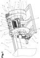
- Fig.1 shows a schematic representation of a wire straightening system 1 for aligning wires 2.
- wires 2 with different diameters can be aligned in the wire straightening system 1.
- the wires 2 fed to the wire straightening system 1 are preferably provided on a wire unwinding device 3. Different wire rolls with wires of different diameters can be accommodated in the wire unwinding device 3.
- the wire straightening system 1 can be followed by a cutting device or other handling devices for further processing of the straightened wire.
- a cutting device or other handling devices for further processing of the straightened wire.
- the straightened wires 2 are preferably used for the production of reinforcement elements, such as reinforcement mats.
- a bearing support 7 can be formed on the machine frame 4, on which a main pivot bearing 8 of the tool holder 5 is arranged.
- the main pivot bearing 8 can, for example, be designed in the form of two bearing blocks that are axially spaced apart from one another.
- the tool holder 5 comprises a bearing shaft 9 which is rotatably received in the main pivot bearing 8 of the tool holder 5.
- the tool holder 5 serves to hold straightening tools 10, which are used to align the wire 2.
- the straightening tools 10 are accommodated between a first end element 11 and a second end element 12 of the tool holder 5 and are mounted in the two end elements 11, 12. It is provided that a rotary bearing 13 is formed for each of the straightening tools 10 in the first end element 11 and in the second end element 12.
- the rotary bearing 13 allows the straightening tools 10 to be rotatable about a tool axis 14 in the tool holder 5.
- At least one straightening element in particular a straightening roller arrangement 15 or straightening jaws, is formed in each of the straightening tools 10.
- a straightening roller arrangement 15 or straightening jaws is formed in each of the straightening tools 10.
- at least two straightening roller arrangements 15 are formed for each straightening tool 10, wherein the straightening rollers of the straightening roller arrangements 15 are tilted to the tool axis 14 of the straightening tool 10, so that when the straightening tool 10 rotates about its tool axis 14, the individual rollers of the straightening roller arrangement 15 not only align the wire material 2, but simultaneously serve as a feed.
- the two end elements 11, 12 can be supported by the straightening tools 10 and the bearing shaft 9.
- a connecting component 16 can be formed which is arranged between the two end elements 11, 12.
- the connecting component 16 can serve to additionally stiffen the tool holder 5.
- the connecting component 16 has a basic shape in the form of a hollow cylinder. This can be realized, for example, by a sheet metal component which, as shown in Fig.1 As can be seen, it is bent into a polygonal hollow cylinder. Alternatively, it is also conceivable that the sheet metal component is rolled, for example, to form a hollow cylinder with a circular cross-section.
- a recess 17 is formed in the connecting component 16, which serves to guide the bearing support 7 of the machine frame 4.
- connecting component 16 in the form of a hollow cylinder, it would also be conceivable for the connecting component 16 to be realized by several individual rods which are connected to the first end element 11 and to the second end element 12.
- a torque transmission unit 18 is provided, by means of which the straightening tool 10 in a straightening position can be torque-coupled to the drive motor 19.
- each of the straightening tools 10 has its own torque transmission unit 18, which can be coupled to the drive motor 19.
- two or more drive motors 19 are provided, which can each be coupled to a straightening tool 10 at the same time. It is therefore also conceivable that two or more straightening tools 10 can be used simultaneously.
- straightening tools 10 with a smaller diameter can be driven by the first drive.
- Straightening tools 10 with a larger diameter can be driven by the second drive.
- both drives can be coupled to the respective straightening tools 10.
- the drive motor 19 is displaceable in the axial direction relative to the torque transmission unit 18 and that a torque coupling 20 is formed, by means of which the torque-transmitting connection between the drive motor 19 and the torque transmission unit 18 can be released as required by axial displacement of the drive motor 19.
- the drive motor 19 In order to be able to move the drive motor 19 axially, it is mounted on the machine frame 14 so that it can move relative to the latter by means of a linear guide 21.
- the linear guide 21 is arranged on the bearing support 7 of the machine frame 4.
- a main drive motor 22 is arranged on the machine frame 4, which serves for the rotation drive of the tool holder 5.
- the main drive motor 22 can be arranged in the area of the first end element 11 of the tool holder 5.
- the main drive motor 22 is coupled to the tool holder 5 by means of a toothed belt 23.
- the drive motor 19 is moved in the axial direction and the torque-transmitting connection between the drive motor 19 and the torque transmission unit 18 is released in the area of the torque coupling 20.
- the tool holder 5 can then be rotated with respect to its central axis of rotation 6 in order to move the last used straightening tool 10 from the straightening position to a rest position. and at the same time to move another straightening tool 10 with another wire 2 accommodated therein from the rest position into the straightening position.
- the drive motor 19 is then moved axially forward again so that the torque coupling 20 again forms a torque connection between the drive motor 19 and the torque transmission unit 18.
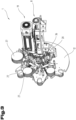
- Fig. 2 shows the wire straightening system 1 in a further perspective view, whereby in comparison to Fig.1 the rear side of the wire straightening system 1 is viewed.
- the same reference symbols or component designations are used as in the previous Fig.1 To avoid unnecessary repetition, please refer to the detailed description in the previous Fig.1 pointed out or referred to.
- a further bearing support 25 of the machine frame 4 is formed, on which a further main pivot bearing 26 is formed, which serves to guide the bearing shaft 9.
- two second end elements 12 are formed, which are arranged at a distance from each other.
- the torque transmission unit 18 has a first drive disk 27 and a second drive disk 28, which are coupled to one another by a traction means 29.
- the first drive pulley 27 and the second drive pulley 28 are designed in the form of a V-belt pulley and a V-belt is used as the traction means 29.
- the two first drive disks 27 of mutually adjacent straightening tools 10 are offset from one another by at least the drive disk width 30.
- every second torque transmission unit 18 is assigned to that second end element 12 which is closer to the straightening tools 10.
- the remaining torque transmission units 18 are assigned to that second end element 12 which is further away from the straightening tools 10.
- every second torque transmission unit can be arranged in a first plane 31 and the remaining torque transmission units 18 can be arranged in a second plane 32.
- tensioning elements 33 are formed in the torque transmission units 18, which serve to tension the traction means 29.
- a parking brake 34 can be designed, by means of which the straightening tools 10 can be clamped in their angular position.
- the parking brake 34 can basically be arranged at any point in the drive train of a straightening tool 10 or directly on the straightening tool 10.
- the parking brake 34 is designed, for example, in the form of a disk brake.
- the parking brake 34 can be designed in the form of a drum brake or in another form.
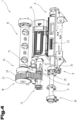
- a second coupling element 36 of a torque coupling 20 is coupled to each torque transmission unit 18.
- the individual parts of the torque coupling 20 are particularly well Fig.5 visible.
- actuating cylinder 42 can be provided which serves to displace the drive motor 19 in the axial direction.
- the actuating cylinder 42 can be designed, for example, in the form of a pneumatic cylinder.
- the torque coupling 20 has a first coupling element 35 which is coupled to the drive motor 19 and a second coupling element 36 which is coupled to the torque transmission unit 18.
- the two coupling elements 35, 36 are designed in the form of a claw coupling.
- a damping element 37 is provided which is arranged between the two coupling elements 35, 36, in particular between their claws and thus serves to dampen the torque transmission.
- an angle centering aid 38 is arranged on the two coupling elements 35, 36, by means of which the sliding of the two coupling elements 35, 36 into one another can be facilitated.
- the angle centering aid 38 can comprise a first centering aid 39 and a second centering aid 40, which also mesh with one another.
- the two centering aids 39, 40 can have centering teeth 41, which are tapered towards the front and thus enable angular centering.
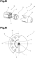
- the straightening tools 10 are arranged at a distance 43 from the central axis of rotation 6. In particular, it is provided that all of the straightening tools 10 have the same distance 43 from the central longitudinal axis 6. Furthermore, it is also provided that all of the straightening tools 10 are arranged within an angle 44 in the tool holder 5, so that when the tool holder 5 is rotated, the individual straightening tools 10 do not collide with the bearing support 7 of the machine frame 4.
- the connecting component 16 is arranged in a similar angular range 44 as the straightening tools 10.
Landscapes
- Engineering & Computer Science (AREA)
- Mechanical Engineering (AREA)
- Wire Processing (AREA)
Claims (13)
- Dispositif de redressage de fil (1) pour redresser un fil (2), comprenant :- un bâti de machine (4) ;- un dispositif de fixation d'outil (5), qui est monté sur le bâti de la machine (4) de manière à pouvoir tourner autour d'un axe de rotation central (6) ;- au moins deux outils de réglage (10) pour différents diamètres de fil, qui sont reçus dans le dispositif de fixation d'outil (5) au moyen de supports de rotation (13) de manière à pouvoir tourner par rapport à des axes d'outil (14) s'étendant parallèlement l'un à l'autre, chacun des outils de réglage (10) ayant au moins un élément de redressement, en particulier un dispositif de rouleau de réglage (15) ou des mâchoires de redressement, dans lequel les outils de réglage (10) sont disposés à une distance (43) de l'axe central de rotation (6) sur le support d'outil (5) et les outils de réglage individuels (10) peuvent être ajustés entre une position de repos et une position de réglage en faisant tourner le support d'outil (5) autour de l'axe central de rotation (6) ;- au moins un moteur d'entraînement (19) pour entraîner l'outil de réglage (10) ;- une unité de transmission de couple (18) pour chaque outil de réglage (10), conçue pour transmettre le couple entre le moteur d'entraînement (19) et l'outil de réglage respectif (10),caractérisé par le fait quele dispositif de maintien de l'outil (5) est conçu de telle sorte que lorsque le L'outil de réglage (10) reste dans les outils de réglage (10) entre la position de repos et la position de réglage du fil (2), les unités de transmission de couple (18) étant montées sur le support d'outil (5) et pouvant tourner autour de l'axe de rotation central (6) avec les outils de réglage associés respectifs (10), et en ce que le moteur d'entraînement (19) est monté sur le bâti de la machine (4) de manière à pouvoir être déplacé axialement par rapport aux unités de transmission de couple (18) et est relié aux unités de transmission de couple (18) au moyen d'un accouplement de couple qui peut être libéré par le déplacement axial.(20) peut être sélectivement couplé aux différentes unités de transmission de couple (18), dans lequel un premier élément de couplage (35) du coupleur (20) est couplé au moteur d'entraînement (19) et un second élément de couplage (36) du coupleur (20) est couplé à chacune des unités de transmission de couple (18), et dans lequel les unités de transmission de couple (18) ont chacune un premier disque d'entraînement (27) couplé au couple de l'outil de réglage (10) et un second disque d'entraînement (28) couplé au couple du second élément de couplage (36) de l'accouplement de couple (20), dans lequel le premier disque d'entraînement (27) et le second disque d'entraînement (28) sont couplés l'un à l'autre au moyen d'un moyen de traction (29), en particulier au moyen d'au moins une courroie trapézoïdale.
- Dispositif de redressage de fil selon la revendication 1, caractérisé par le fait que les outils de dressage individuels (10) sont couplés à un frein de stationnement (34).
- Dispositif de redressage de fil selon l'une des revendications précédentes, caractérisé en ce que tous les outils de réglage (10) sont disposés à un angle (44) inférieur à 270°, en particulier inférieur à 180°, par rapport à l'axe central de rotation (6) sur le support d'outils (5).
- Dispositif de dressage de fil selon l'une des revendications précédentes, caractérisé en ce que le dispositif de maintien de l'outil (5) est rotatif selon un angle (44) inférieur à 180° par rapport à l'axe central de rotation (6).
- Dispositif de dressage de fil selon l'une des revendications précédentes, caractérisé par le fait que le dispositif de fixation d'outil (5) comporte un premier élément frontal (11), dans lequel est formé le premier des supports rotatifs (13) pour le montage des dispositifs de fixation d'outil (5), et comporte un deuxième élément frontal (12), dans lequel est formé le deuxième des supports rotatifs (13) pour le montage des dispositifs de fixation d'outil (5), dans lequel les deux éléments frontaux (11, 12) sont couplés l'un à l'autre au moyen d'un composant de connexion (16) et dans lequel un évidement (17) est formé dans le composant de connexion (16), à travers lequel un support de roulement (7) du cadre de la machine (4) est guidé, dans lequel un support de rotation principal (8) du dispositif de fixation d'outil (5) est disposé sur le support de roulement (7) du cadre de la machine (4).
- Dispositif de redressage de fil selon la revendication 5, caractérisé par le fait que le moteur d'entraînement (19) pour l'entraînement de la poignée de réglage (10) est disposée entre les deux éléments frontaux (11, 12) et est montée axialement déplaçable sur le support de roulement (7) du bâti de la machine (4).
- Dispositif de redressage de fil selon l'une des revendications précédentes, caractérisé par le fait que les deux premiers disques d'entraînement (27) d'unités de transmission de couple (18) mutuellement adjacentes sont décalés axialement l'un par rapport à l'autre d'au moins une largeur de disque d'entraînement (30).
- Dispositif de redressage de fil selon l'une des revendications précédentes, caractérisé en ce que l'accouplement à couple (20) est conçu sous la forme d'un accouplement à griffes, le premier élément d'accouplement (35) et le second élément d'accouplement (36) ayant des griffes qui sont conçues pour s'engager l'une dans l'autre et qui servent à transmettre le couple.
- Dispositif de redressage de fil selon l'une des revendications précédentes, caractérisé en ce qu'une aide de centrage angulaire (38) est disposée sur les deux éléments d'accouplement (35, 36), qui sert à rapprocher les deux éléments d'accouplement (35, 36).
- Dispositif de dressage de fil selon l'une des revendications précédentes, caractérisé en ce qu'un moteur d'entraînement principal (22) est formé pour l'entraînement rotatif du dispositif de fixation d'outil (5), le moteur d'entraînement principal (22) étant disposé à l'extérieur du dispositif de fixation d'outil (5) dans la zone du premier élément frontal (11).
- Méthode d'alignement des fils (2) de diamètres différents,
utiliser un dispositif de redressage de fil (1) selon l'une des revendications précédentes, caractérisé en ce que la méthode comprend les étapes suivantes :- Fournir un premier fil (2) avec un premier diamètre de fil en maintenant le premier fil (2) dans un premier outil de mise en place (10) ;- Fournir un deuxième fil (2) avec un deuxième diamètre de fil en maintenant le deuxième fil (2) dans un deuxième outil de réglage (10) ;- aligner le premier fil (2) en faisant tourner le premier outil de réglage (10) autour de son axe (14), le premier outil de réglage (10) étant dans sa position de réglage ;- Coupe du premier fil (2) et déplacement axial du moteur d'entraînement (19) pour libérer la transmission du couple entre le moteur d'entraînement (19) et l'outil de réglage (10) qui doit être retiré de la position de réglage ;- Rotation du dispositif de maintien de l'outil (5) autour de l'axe central de rotation (6), de sorte que le premier outil de réglage (10) soit déplacé de sa position de réglage vers une position de repos et que le second outil de réglage (10) soit déplacé d'une position de repos vers la position de réglage, le premier fil (2) restant maintenu dans le premier outil de réglage (10) et le second fil (2) restant maintenu dans le second outil de réglage (10) ;- Déplacement axial du moteur d'entraînement (19) pour établir la transmission du couple entre le moteur d'entraînement (19) et l'outil de réglage (10) transporté dans la position de réglage ; Alignement du deuxième fil (2) par rotation du deuxième outil de réglage (10) autour de son axe (14), le deuxième outil de réglage (10) étant dans sa position de réglage. - Méthode selon la revendication 11, caractérisé par le fait que, pour faire tourner le porte-outil (5) autour de l'axe central de rotation (6), le premier outil de réglage (10) et le second outil de réglage (10) sont serrés au moyen du frein de stationnement (34) de manière à ce qu'ils ne puissent pas tourner autour de leur axe d'outil (14).
- Méthode selon la revendication 11 ou 12, caractérisé par le fait qu'avant le déplacement axial du moteur d'entraînement (19) pour établir la transmission du couple entre le moteur d'entraînement (19) et l'outil de réglage (10) transporté dans la position de réglage, l'arbre d'entraînement du moteur d'entraînement (19) est déplacé dans une position angulaire connue depuis le dernier engagement avec l'outil de réglage (10) transporté dans la position de réglage.
Applications Claiming Priority (2)
| Application Number | Priority Date | Filing Date | Title |
|---|---|---|---|
| ATA50217/2017A AT519813A1 (de) | 2017-03-20 | 2017-03-20 | Drahtrichtanlage und Verfahren zum Ausrichten von Drähten mittels der Drahtrichtanlage |
| PCT/AT2018/060068 WO2018170525A1 (fr) | 2017-03-20 | 2018-03-16 | Installation de dressage de fils et procédé pour le dressage de fils au moyen de l'installation de dressage de fils |
Publications (3)
| Publication Number | Publication Date |
|---|---|
| EP3600712A1 EP3600712A1 (fr) | 2020-02-05 |
| EP3600712C0 EP3600712C0 (fr) | 2024-08-21 |
| EP3600712B1 true EP3600712B1 (fr) | 2024-08-21 |
Family
ID=62044433
Family Applications (1)
| Application Number | Title | Priority Date | Filing Date |
|---|---|---|---|
| EP18719416.2A Active EP3600712B1 (fr) | 2017-03-20 | 2018-03-16 | Installation de dressage de fils et procédé pour le dressage de fils au moyen de l'installation de dressage de fils |
Country Status (3)
| Country | Link |
|---|---|
| EP (1) | EP3600712B1 (fr) |
| AT (1) | AT519813A1 (fr) |
| WO (1) | WO2018170525A1 (fr) |
Families Citing this family (1)
| Publication number | Priority date | Publication date | Assignee | Title |
|---|---|---|---|---|
| CN115007767B (zh) * | 2022-07-12 | 2025-12-23 | 威睿电动汽车技术(宁波)有限公司 | 一种柔性转盘装置 |
Family Cites Families (5)
| Publication number | Priority date | Publication date | Assignee | Title |
|---|---|---|---|---|
| DE2733407A1 (de) * | 1977-07-23 | 1979-02-01 | Krupp Gmbh | Richtmaschine fuer betonstahl |
| DE3338915A1 (de) * | 1983-10-27 | 1985-05-09 | Mecapec S.A., Schmerikon | Vorrichtung zum richten und ablaengen von draht- oder stabfoermigem material |
| DE19709733C2 (de) * | 1997-03-10 | 2000-04-13 | Theis Klaus | Vorrichtung zum rotierenden Richten von Draht |
| CN103128197B (zh) * | 2013-03-21 | 2015-06-17 | 建科机械(天津)股份有限公司 | 钢筋调直机的多规格移动调直机构 |
| AT517095B1 (de) * | 2015-04-28 | 2016-11-15 | Evg Entwicklungs- U Verwertungs-Gesellschaft M B H | Draht-Richtanlage |
-
2017
- 2017-03-20 AT ATA50217/2017A patent/AT519813A1/de not_active Application Discontinuation
-
2018
- 2018-03-16 WO PCT/AT2018/060068 patent/WO2018170525A1/fr not_active Ceased
- 2018-03-16 EP EP18719416.2A patent/EP3600712B1/fr active Active
Also Published As
| Publication number | Publication date |
|---|---|
| EP3600712A1 (fr) | 2020-02-05 |
| EP3600712C0 (fr) | 2024-08-21 |
| AT519813A1 (de) | 2018-10-15 |
| WO2018170525A1 (fr) | 2018-09-27 |
Similar Documents
| Publication | Publication Date | Title |
|---|---|---|
| EP2988885B1 (fr) | Dresseuse à réglage individuel et dispositif de changement d'outil | |
| EP1640125B1 (fr) | Procédé et dispositif pour couper une tige guidée continûment dans des articles en forme de tige | |
| DE10015340A1 (de) | Walzgerüst für Walzstraßen zum Walzen von metallischen Rohren, Stäben oder Drähten | |
| CH652947A5 (de) | Drahtbiegemaschine. | |
| EP1863604B1 (fr) | Dispositif de formage libre de profiles allonges, en particulier de tubes, et dispositif combine de formage libre et d'etirage de profiles allonges, en particulier de tubes | |
| DE10015339A1 (de) | Walzgerüst für Walzstraßen zum Walzen von metallischen Rohren, Stäben oder Drähten | |
| EP0154349A2 (fr) | Dispositif pour changer des outils ou des objets similaires dans la broche d'une machine-outil | |
| EP1676655B1 (fr) | Dispositif d'avance avec mâchoire de serrage souple | |
| EP2429731B1 (fr) | Mandrin de serrage pour laminoir à pas de pèlerin | |
| DE29911152U1 (de) | Werkzeugvorrichtung zur spanenden Bearbeitung tafelförmiger Werkstücke | |
| EP2532456A2 (fr) | Plieuse et outil de pliage | |
| DE3811995C2 (fr) | ||
| EP1468754A2 (fr) | Dispositif de fixation au moins un rouleau d'une machine de roulage | |
| EP3600712A1 (fr) | Installation de dressage de fils et procédé pour le dressage de fils au moyen de l'installation de dressage de fils | |
| EP3436205A1 (fr) | Laminoir à froid à pas de pèlerin et procédé de fabrication d'un tube | |
| DE102021125587B3 (de) | Vorrichtung und Verfahren zum Ausrichten von Würsten | |
| EP1413369B1 (fr) | Dispositif et procédé de cintrage d'éléments sous forme de barres | |
| EP2676558B1 (fr) | Dispositif de séparation d'un faisceau acheminé sans fin d'un produit de l'industrie de traitement du tabac en tiges individuelles | |
| EP2371480A1 (fr) | Centre de traitement de profilés | |
| EP2420350A2 (fr) | Dispositif d'avance et machine, notamment machine à écorcer | |
| DE102007049790A1 (de) | Vorrichtung zum Trennen eines längs eines Förder-Durchgangs bewegbaren plastischen Stranges, mit einem Kerbantrieb | |
| DE102005056649B3 (de) | Vorrichtung zum Halten von wenigstens zwei Walzen einer Walzmaschine und Walzmaschine | |
| DE2503284C3 (de) | Walzendrehbank | |
| DE1402071A1 (de) | Verfahren und Vorrichtung zum automatischen Herstellen von mit Querrippen versehenenRohren,insbesondere fuer Waermeaustauscher | |
| EP0564445A1 (fr) | Dispositif pour l'alimentation alternative de matériau à une installation de travail |
Legal Events
| Date | Code | Title | Description |
|---|---|---|---|
| STAA | Information on the status of an ep patent application or granted ep patent |
Free format text: STATUS: UNKNOWN |
|
| STAA | Information on the status of an ep patent application or granted ep patent |
Free format text: STATUS: THE INTERNATIONAL PUBLICATION HAS BEEN MADE |
|
| PUAI | Public reference made under article 153(3) epc to a published international application that has entered the european phase |
Free format text: ORIGINAL CODE: 0009012 |
|
| STAA | Information on the status of an ep patent application or granted ep patent |
Free format text: STATUS: REQUEST FOR EXAMINATION WAS MADE |
|
| 17P | Request for examination filed |
Effective date: 20191018 |
|
| AK | Designated contracting states |
Kind code of ref document: A1 Designated state(s): AL AT BE BG CH CY CZ DE DK EE ES FI FR GB GR HR HU IE IS IT LI LT LU LV MC MK MT NL NO PL PT RO RS SE SI SK SM TR |
|
| AX | Request for extension of the european patent |
Extension state: BA ME |
|
| DAV | Request for validation of the european patent (deleted) | ||
| DAX | Request for extension of the european patent (deleted) | ||
| RAP1 | Party data changed (applicant data changed or rights of an application transferred) |
Owner name: APILION MACHINES + SERVICES GMBH |
|
| RIN1 | Information on inventor provided before grant (corrected) |
Inventor name: RAPPERSTORFER, HUBERT |
|
| RAP3 | Party data changed (applicant data changed or rights of an application transferred) |
Owner name: APILION MACHINES + SERVICES GMBH |
|
| STAA | Information on the status of an ep patent application or granted ep patent |
Free format text: STATUS: EXAMINATION IS IN PROGRESS |
|
| 17Q | First examination report despatched |
Effective date: 20221014 |
|
| GRAP | Despatch of communication of intention to grant a patent |
Free format text: ORIGINAL CODE: EPIDOSNIGR1 |
|
| STAA | Information on the status of an ep patent application or granted ep patent |
Free format text: STATUS: GRANT OF PATENT IS INTENDED |
|
| INTG | Intention to grant announced |
Effective date: 20240311 |
|
| GRAS | Grant fee paid |
Free format text: ORIGINAL CODE: EPIDOSNIGR3 |
|
| GRAA | (expected) grant |
Free format text: ORIGINAL CODE: 0009210 |
|
| STAA | Information on the status of an ep patent application or granted ep patent |
Free format text: STATUS: THE PATENT HAS BEEN GRANTED |
|
| AK | Designated contracting states |
Kind code of ref document: B1 Designated state(s): AL AT BE BG CH CY CZ DE DK EE ES FI FR GB GR HR HU IE IS IT LI LT LU LV MC MK MT NL NO PL PT RO RS SE SI SK SM TR |
|
| REG | Reference to a national code |
Ref country code: GB Ref legal event code: FG4D Free format text: NOT ENGLISH |
|
| REG | Reference to a national code |
Ref country code: CH Ref legal event code: EP |
|
| REG | Reference to a national code |
Ref country code: DE Ref legal event code: R096 Ref document number: 502018015036 Country of ref document: DE |
|
| REG | Reference to a national code |
Ref country code: IE Ref legal event code: FG4D Free format text: LANGUAGE OF EP DOCUMENT: GERMAN |
|
| U01 | Request for unitary effect filed |
Effective date: 20240828 |
|
| U07 | Unitary effect registered |
Designated state(s): AT BE BG DE DK EE FI FR IT LT LU LV MT NL PT RO SE SI Effective date: 20240909 |
|
| PG25 | Lapsed in a contracting state [announced via postgrant information from national office to epo] |
Ref country code: NO Free format text: LAPSE BECAUSE OF FAILURE TO SUBMIT A TRANSLATION OF THE DESCRIPTION OR TO PAY THE FEE WITHIN THE PRESCRIBED TIME-LIMIT Effective date: 20241121 |
|
| PG25 | Lapsed in a contracting state [announced via postgrant information from national office to epo] |
Ref country code: GR Free format text: LAPSE BECAUSE OF FAILURE TO SUBMIT A TRANSLATION OF THE DESCRIPTION OR TO PAY THE FEE WITHIN THE PRESCRIBED TIME-LIMIT Effective date: 20241122 Ref country code: PL Free format text: LAPSE BECAUSE OF FAILURE TO SUBMIT A TRANSLATION OF THE DESCRIPTION OR TO PAY THE FEE WITHIN THE PRESCRIBED TIME-LIMIT Effective date: 20240821 |
|
| PG25 | Lapsed in a contracting state [announced via postgrant information from national office to epo] |
Ref country code: IS Free format text: LAPSE BECAUSE OF FAILURE TO SUBMIT A TRANSLATION OF THE DESCRIPTION OR TO PAY THE FEE WITHIN THE PRESCRIBED TIME-LIMIT Effective date: 20241221 |
|
| PG25 | Lapsed in a contracting state [announced via postgrant information from national office to epo] |
Ref country code: HR Free format text: LAPSE BECAUSE OF FAILURE TO SUBMIT A TRANSLATION OF THE DESCRIPTION OR TO PAY THE FEE WITHIN THE PRESCRIBED TIME-LIMIT Effective date: 20240821 |
|
| PG25 | Lapsed in a contracting state [announced via postgrant information from national office to epo] |
Ref country code: RS Free format text: LAPSE BECAUSE OF FAILURE TO SUBMIT A TRANSLATION OF THE DESCRIPTION OR TO PAY THE FEE WITHIN THE PRESCRIBED TIME-LIMIT Effective date: 20241121 Ref country code: ES Free format text: LAPSE BECAUSE OF FAILURE TO SUBMIT A TRANSLATION OF THE DESCRIPTION OR TO PAY THE FEE WITHIN THE PRESCRIBED TIME-LIMIT Effective date: 20240821 |
|
| PG25 | Lapsed in a contracting state [announced via postgrant information from national office to epo] |
Ref country code: RS Free format text: LAPSE BECAUSE OF FAILURE TO SUBMIT A TRANSLATION OF THE DESCRIPTION OR TO PAY THE FEE WITHIN THE PRESCRIBED TIME-LIMIT Effective date: 20241121 Ref country code: PL Free format text: LAPSE BECAUSE OF FAILURE TO SUBMIT A TRANSLATION OF THE DESCRIPTION OR TO PAY THE FEE WITHIN THE PRESCRIBED TIME-LIMIT Effective date: 20240821 Ref country code: NO Free format text: LAPSE BECAUSE OF FAILURE TO SUBMIT A TRANSLATION OF THE DESCRIPTION OR TO PAY THE FEE WITHIN THE PRESCRIBED TIME-LIMIT Effective date: 20241121 Ref country code: IS Free format text: LAPSE BECAUSE OF FAILURE TO SUBMIT A TRANSLATION OF THE DESCRIPTION OR TO PAY THE FEE WITHIN THE PRESCRIBED TIME-LIMIT Effective date: 20241221 Ref country code: HR Free format text: LAPSE BECAUSE OF FAILURE TO SUBMIT A TRANSLATION OF THE DESCRIPTION OR TO PAY THE FEE WITHIN THE PRESCRIBED TIME-LIMIT Effective date: 20240821 Ref country code: GR Free format text: LAPSE BECAUSE OF FAILURE TO SUBMIT A TRANSLATION OF THE DESCRIPTION OR TO PAY THE FEE WITHIN THE PRESCRIBED TIME-LIMIT Effective date: 20241122 Ref country code: ES Free format text: LAPSE BECAUSE OF FAILURE TO SUBMIT A TRANSLATION OF THE DESCRIPTION OR TO PAY THE FEE WITHIN THE PRESCRIBED TIME-LIMIT Effective date: 20240821 |
|
| PG25 | Lapsed in a contracting state [announced via postgrant information from national office to epo] |
Ref country code: SM Free format text: LAPSE BECAUSE OF FAILURE TO SUBMIT A TRANSLATION OF THE DESCRIPTION OR TO PAY THE FEE WITHIN THE PRESCRIBED TIME-LIMIT Effective date: 20240821 |
|
| PG25 | Lapsed in a contracting state [announced via postgrant information from national office to epo] |
Ref country code: CZ Free format text: LAPSE BECAUSE OF FAILURE TO SUBMIT A TRANSLATION OF THE DESCRIPTION OR TO PAY THE FEE WITHIN THE PRESCRIBED TIME-LIMIT Effective date: 20240821 |
|
| PG25 | Lapsed in a contracting state [announced via postgrant information from national office to epo] |
Ref country code: SK Free format text: LAPSE BECAUSE OF FAILURE TO SUBMIT A TRANSLATION OF THE DESCRIPTION OR TO PAY THE FEE WITHIN THE PRESCRIBED TIME-LIMIT Effective date: 20240821 |
|
| U20 | Renewal fee for the european patent with unitary effect paid |
Year of fee payment: 8 Effective date: 20250325 |
|
| PLBE | No opposition filed within time limit |
Free format text: ORIGINAL CODE: 0009261 |
|
| STAA | Information on the status of an ep patent application or granted ep patent |
Free format text: STATUS: NO OPPOSITION FILED WITHIN TIME LIMIT |
|
| 26N | No opposition filed |
Effective date: 20250522 |
|
| PG25 | Lapsed in a contracting state [announced via postgrant information from national office to epo] |
Ref country code: MC Free format text: LAPSE BECAUSE OF FAILURE TO SUBMIT A TRANSLATION OF THE DESCRIPTION OR TO PAY THE FEE WITHIN THE PRESCRIBED TIME-LIMIT Effective date: 20240821 |
|
| REG | Reference to a national code |
Ref country code: CH Ref legal event code: H13 Free format text: ST27 STATUS EVENT CODE: U-0-0-H10-H13 (AS PROVIDED BY THE NATIONAL OFFICE) Effective date: 20251023 |
|
| GBPC | Gb: european patent ceased through non-payment of renewal fee |
Effective date: 20250316 |
|
| PG25 | Lapsed in a contracting state [announced via postgrant information from national office to epo] |
Ref country code: GB Free format text: LAPSE BECAUSE OF NON-PAYMENT OF DUE FEES Effective date: 20250316 |
|
| PG25 | Lapsed in a contracting state [announced via postgrant information from national office to epo] |
Ref country code: CH Free format text: LAPSE BECAUSE OF NON-PAYMENT OF DUE FEES Effective date: 20250331 |
|
| PG25 | Lapsed in a contracting state [announced via postgrant information from national office to epo] |
Ref country code: IE Free format text: LAPSE BECAUSE OF NON-PAYMENT OF DUE FEES Effective date: 20250316 |
|
| U20 | Renewal fee for the european patent with unitary effect paid |
Year of fee payment: 9 Effective date: 20260327 |
|
| PG25 | Lapsed in a contracting state [announced via postgrant information from national office to epo] |
Ref country code: CY Free format text: LAPSE BECAUSE OF FAILURE TO SUBMIT A TRANSLATION OF THE DESCRIPTION OR TO PAY THE FEE WITHIN THE PRESCRIBED TIME-LIMIT Effective date: 20240821 |
|
| PG25 | Lapsed in a contracting state [announced via postgrant information from national office to epo] |
Ref country code: TR Free format text: LAPSE BECAUSE OF FAILURE TO SUBMIT A TRANSLATION OF THE DESCRIPTION OR TO PAY THE FEE WITHIN THE PRESCRIBED TIME-LIMIT Effective date: 20240821 |