EP2676801A1 - Siebdruckschablone - Google Patents
Siebdruckschablone Download PDFInfo
- Publication number
- EP2676801A1 EP2676801A1 EP13155527.8A EP13155527A EP2676801A1 EP 2676801 A1 EP2676801 A1 EP 2676801A1 EP 13155527 A EP13155527 A EP 13155527A EP 2676801 A1 EP2676801 A1 EP 2676801A1
- Authority
- EP
- European Patent Office
- Prior art keywords
- plate
- silk
- thin sheet
- screen thin
- perimeter
- Prior art date
- Legal status (The legal status is an assumption and is not a legal conclusion. Google has not performed a legal analysis and makes no representation as to the accuracy of the status listed.)
- Withdrawn
Links
- 238000003466 welding Methods 0.000 claims description 11
- 239000000463 material Substances 0.000 claims description 4
- 238000000034 method Methods 0.000 claims description 4
- 238000004519 manufacturing process Methods 0.000 claims description 3
- 238000000465 moulding Methods 0.000 claims description 3
- 238000005304 joining Methods 0.000 claims 1
- 238000003754 machining Methods 0.000 description 5
- 238000012986 modification Methods 0.000 description 3
- 230000004048 modification Effects 0.000 description 3
- PXHVJJICTQNCMI-UHFFFAOYSA-N Nickel Chemical compound [Ni] PXHVJJICTQNCMI-UHFFFAOYSA-N 0.000 description 2
- 239000004952 Polyamide Substances 0.000 description 2
- 208000027418 Wounds and injury Diseases 0.000 description 2
- 230000006378 damage Effects 0.000 description 2
- 208000014674 injury Diseases 0.000 description 2
- MOFOBJHOKRNACT-UHFFFAOYSA-N nickel silver Chemical compound [Ni].[Ag] MOFOBJHOKRNACT-UHFFFAOYSA-N 0.000 description 2
- 239000010956 nickel silver Substances 0.000 description 2
- 229920002647 polyamide Polymers 0.000 description 2
- 239000010935 stainless steel Substances 0.000 description 2
- 229910001220 stainless steel Inorganic materials 0.000 description 2
- 150000001298 alcohols Chemical class 0.000 description 1
- 238000005452 bending Methods 0.000 description 1
- 239000003518 caustics Substances 0.000 description 1
- 238000005520 cutting process Methods 0.000 description 1
- 230000001419 dependent effect Effects 0.000 description 1
- 239000003292 glue Substances 0.000 description 1
- 231100001261 hazardous Toxicity 0.000 description 1
- 238000003780 insertion Methods 0.000 description 1
- 230000037431 insertion Effects 0.000 description 1
- 239000000155 melt Substances 0.000 description 1
- 239000012768 molten material Substances 0.000 description 1
- 229910052759 nickel Inorganic materials 0.000 description 1
- 239000002861 polymer material Substances 0.000 description 1
- 238000002360 preparation method Methods 0.000 description 1
- 239000000126 substance Substances 0.000 description 1
- XLYOFNOQVPJJNP-UHFFFAOYSA-N water Substances O XLYOFNOQVPJJNP-UHFFFAOYSA-N 0.000 description 1
Images


Classifications
-
- B—PERFORMING OPERATIONS; TRANSPORTING
- B41—PRINTING; LINING MACHINES; TYPEWRITERS; STAMPS
- B41N—PRINTING PLATES OR FOILS; MATERIALS FOR SURFACES USED IN PRINTING MACHINES FOR PRINTING, INKING, DAMPING, OR THE LIKE; PREPARING SUCH SURFACES FOR USE AND CONSERVING THEM
- B41N1/00—Printing plates or foils; Materials therefor
- B41N1/24—Stencils; Stencil materials; Carriers therefor
- B41N1/248—Mechanical details, e.g. fixation holes, reinforcement or guiding means; Perforation lines; Ink holding means; Visually or otherwise detectable marking means; Stencil units
Definitions
- the present invention relates to a silk-screen thin sheet of the type recited in the preamble of Claim 1.
- the invention relates to a thin sheet suitable to be machined by machining centres which, by performing laser or water cutting, form a die for the positioning of glues for electronic components or other substances.
- silk-screen thin sheets are composed of plates, generally rectangular and made, for example from stainless steel, nickel silver, polyamide or nickel characterised by a thickness to the order of several micron.
- Said thin sheets have, for the purpose of permitting the tensioning thereof, a series of through openings along the lateral edges, appropriately distanced from said edges and suitable for enabling the plate to be gripped by the tensioning arms.
- the tensioning arms comprise specific gripping teeth which engage in the through openings and thus place the plate in tension before it is machined.
- the prior art described above has several significant drawbacks.
- a first significant problem is the fact that the silk-screen thin sheets are extremely difficult and dangerous to handle.
- the thin sheets are extremely flexible and when moved manually by the operator, are subject to buckling and bending which complicates the work.
- a further problem is represented by the fact that silk-screen thin sheets, both on account of their reduced thickness and of the difficulty in handling, are hazardous to the operator who is, in fact, prone to possible cuts or other injury.
- silk-screen thin sheets are known of fitted with a frame connected to the edges of the plate and defining a different gripping point for the tensioning arms.
- a first significant drawback is the fact that the frames cannot be used with standard type arms.
- the technical purpose of the present invention is to devise a silk-screen thin sheet able to substantially overcome the drawbacks mentioned above.
- one important aim of the invention is to provide a silk-screen thin sheet that is both easy and simple to handle.
- Another important aim of the invention is to create a simple and economical silk-screen thin sheet.
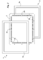
- reference numeral 1 globally denotes the silk-screen thin sheet according to the invention.
- the plate 2 comprises a plate 2 provided with a perimeter and comprising a plurality of grip openings 2a suitable to enable said silk-screen thin sheet 1 to be tensioned and a stiffening frame 3 at least partly surrounding the perimeter of the plate 2.
- the plate 2 is made from stainless steel, nickel silver, polyamide or other similar material and is characterised by a thickness of 80 ⁇ m to 300 ⁇ m, the plate 2 has a polygonal, preferably rectangular or square profile.
- the grip openings 2a are composed of through holes having a circular, polygonal or other cross-section suitable to enable easy gripping by the insertion teeth of the tensioning arms on a machining centre for silk-screen thin sheets.
- Such grip openings 2a are made at a suitable engagement distance from the perimeter of the plate 2 so as to prevent the silk-screen thin sheet 1 from breaking during the tensioning thereof.
- the grip openings 2a are made along the perimeter of the plate 2 and the engagement distance is substantially 0.5 cm to 3 cm, and more specifically, substantially 0.5 to 1.5 cm.
- the plate 2 comprises, as well as said grip openings 2a, through cavities 2b in correspondence of which the stiffening frame 3 is suitable for engaging the plate 2.
- the through cavities 2b are at a lesser distance from the perimeter than the engagement distance so as to find themselves at a lesser distance from the perimeter in relation to the grip openings 2a.
- the through cavities 2b are made between the grip openings 2a and the perimeter.
- the through cavities 2b are made along the perimeter and, in the case in which the plate 2 has a polygonal profile, at the corners of the polygonal profile of the plate 2.
- the through cavities are made both at the perimeter of the plate 2 and between the grip openings 2a and the perimeter, as shown in Fig. 2 .
- the stiffening frame 3 which surrounds at least partly and preferably totally, the perimeter of the plate 2, originally and advantageously does not overlap and is external to the grip openings 2a and is suitable to stiffen said plate 2.
- the stiffening frame 3 is made from polymer material, preferably from PVC or the like, so as to be resistant to alcohols and similar corrosive agents.
- connection between the plate 2 and the stiffening frame 3 is of the irresolvable type, preferably performed by thermal welding, and even more preferably by ultrasonic welding 3a as described below in more detail so as to make the plate 2 and the stiffening frame 3 integral with each other.
- the stiffening frame 3 is preferably made by moulding two portions 3b, in use one above the plane of the plate 2 and one below, and subsequent welding, as previously specified of the two portions 3b as schematised in Fig. 2 ;
- the stiffening frame 3 comprises one or more profiles suitable to engage the plate 2 along at least one portion of the perimeter of said plate 2 and preferably along the entire perimeter.
- the profiles are consequently, made by protrusion or other similar machining suitable to define, for said profiles, a cross-section extending along a main direction of extension.
- the stiffening frame 3 installed comprises an engagement mouth substantially counter-shaped to the lateral profile of the plate 2 so as to enable the profiles 3b to be connected to the plate 2 substantially by engagement.
- the engagement mouth of the profiles 3b is a substantially rectangular shape of a height practically equal to the thickness of the plate 2, and preferably close to 0.3 mm, and of a width substantially less than 1cm, preferably 2 mm to 8 mm.
- the frame 3 rather is preferably of a total width of 5mm to 15 mm and a height of 3 mm to 15 mm.
- connection between the ends of the profiles 3b is performed by ultrasonic welding 3a in correspondence with at least some of the through cavities 2b.
- the operator prepares the plate 2 making the grip openings 2a thereon at an appropriate engagement distance from the perimeter of the plate 2 and through cavities 2b on the perimeter and /or at a lesser distance from the perimeter than the engagement distance.
- the stiffening frame 3 is associated to the plate 2 by overlapping the two portions 3b and interposing the plate 2 and making, at said through cavities 2b, a joint, and in particular the welding described, of the stiffening frame 3.
- the operator by means of ultrasonic welding melts the frame 3 in correspondence with the cavities 2b.
- the molten material as shown in Fig.3 crosses the through cavities 2b and once solidified, irresolvable connects the components of the stiffening frame 3 to each other and, at the same time, the stiffening frame 3 to the plate 2.
- the invention achieves some important advantages.
- a first advantage is the fact that the silk-screen thin sheet 1 is extremely practical and easy to handle.
- Such advantage is represented by the presence of the stiffening frame 3 which, surrounding the plate 2, lends rigidity to the silk-screen thin sheet 1 and, thus, ease of handling of said thin sheet 1.
- the presence of the stiffening frame 3 prevents the silk-screen thin sheet 1 from flexing and curving thus enabling it to maintain a substantially flat shape.
- Another advantage is the extreme safety when handling the silk-screen thin sheet 1.
- stiffening frame 3 makes it possible to conceal the edge of the plate 2 and, thus, to prevent the operator from injury or cuts when handling.
- one advantage is the fact that the silk-screen thin sheet 1 can be used with the tensioning instruments and, in particular, can be tensioned with the tensioning arms currently provided.
Landscapes
- Engineering & Computer Science (AREA)
- Mechanical Engineering (AREA)
- Lining Or Joining Of Plastics Or The Like (AREA)
- Materials For Medical Uses (AREA)
Applications Claiming Priority (1)
| Application Number | Priority Date | Filing Date | Title |
|---|---|---|---|
| IT000264A ITMI20120264A1 (it) | 2012-02-23 | 2012-02-23 | Lamina serigrafica |
Publications (1)
| Publication Number | Publication Date |
|---|---|
| EP2676801A1 true EP2676801A1 (de) | 2013-12-25 |
Family
ID=45999935
Family Applications (1)
| Application Number | Title | Priority Date | Filing Date |
|---|---|---|---|
| EP13155527.8A Withdrawn EP2676801A1 (de) | 2012-02-23 | 2013-02-15 | Siebdruckschablone |
Country Status (2)
| Country | Link |
|---|---|
| EP (1) | EP2676801A1 (de) |
| IT (1) | ITMI20120264A1 (de) |
Citations (2)
| Publication number | Priority date | Publication date | Assignee | Title |
|---|---|---|---|---|
| WO2001038094A1 (en) * | 1999-11-20 | 2001-05-31 | Newman Eugene F Jr | Improved bordered screens |
| WO2004105452A1 (de) * | 2003-05-23 | 2004-12-02 | Walter Jun Priessnitz | Abdeckschablone und abdeckschabloneneinheit |
-
2012
- 2012-02-23 IT IT000264A patent/ITMI20120264A1/it unknown
-
2013
- 2013-02-15 EP EP13155527.8A patent/EP2676801A1/de not_active Withdrawn
Patent Citations (2)
| Publication number | Priority date | Publication date | Assignee | Title |
|---|---|---|---|---|
| WO2001038094A1 (en) * | 1999-11-20 | 2001-05-31 | Newman Eugene F Jr | Improved bordered screens |
| WO2004105452A1 (de) * | 2003-05-23 | 2004-12-02 | Walter Jun Priessnitz | Abdeckschablone und abdeckschabloneneinheit |
Also Published As
| Publication number | Publication date |
|---|---|
| ITMI20120264A1 (it) | 2013-08-24 |
Similar Documents
| Publication | Publication Date | Title |
|---|---|---|
| JP2005532913A (ja) | 交換可能なダイプレスシステム及び方法 | |
| EP2676801A1 (de) | Siebdruckschablone | |
| CA2817938A1 (en) | Nailing plate | |
| EP3784501B1 (de) | Tapetenschneidvorrichtung | |
| JP5627884B2 (ja) | 丸鋸ガイド装置 | |
| JP5246579B2 (ja) | 間仕切支柱用下地補強材取付け金具 | |
| CN212400402U (zh) | 一种用于保护膜的平行定位接头治具 | |
| KR100641336B1 (ko) | 프레스용 칼금형 | |
| KR101888994B1 (ko) | 원자재 로스를 최소화하는 터치 스크린 패널용 테이프 어셈블리 제조 방법 및 그에 따라 제조되는 터치 스크린 패널용 테이프 어셈블리 | |
| CN205362817U (zh) | 一种邮报箱原料板毛边剪裁机构 | |
| KR20140069636A (ko) | 패널의 처짐 방지용 클램프장치 | |
| CN212437564U (zh) | 一种拖鞋生产用鞋底裁剪装置 | |
| JP6623931B2 (ja) | 切断用定規 | |
| CN213618342U (zh) | 一种组装贴合治具 | |
| CN105252149B (zh) | 大尺寸腔体结构薄壁件的激光切割焊接夹具及焊接方法 | |
| EP2087988A1 (de) | Verfahren zur Abdichtung hohler mehrwandiger Tafeln und dabei gewonnene Tafeln | |
| EP1645398A1 (de) | Einrichtung und Verfahren zur Herstellung von Kunststoffteilen mit einer Beschichtung | |
| KR101562268B1 (ko) | 대형디스플레이 백커버용 트리밍장치 | |
| CN214392637U (zh) | 一种锯条加工用割齿装置 | |
| JPH084167Y2 (ja) | 折曲げ機の金型 | |
| CN206048278U (zh) | 一种新型引线框架板裁剪钳 | |
| CN110508640B (zh) | 一种扶梯地铁项目斜扶手盖板检测整形装置 | |
| CN111941864B (zh) | 一种用于保护膜的平行定位接头治具 | |
| KR100504665B1 (ko) | 콘크리트접착용 강섬유 컷터의 고정장치 | |
| CN210188312U (zh) | 一种方便移动的打包扣装置 |
Legal Events
| Date | Code | Title | Description |
|---|---|---|---|
| PUAI | Public reference made under article 153(3) epc to a published international application that has entered the european phase |
Free format text: ORIGINAL CODE: 0009012 |
|
| AK | Designated contracting states |
Kind code of ref document: A1 Designated state(s): AL AT BE BG CH CY CZ DE DK EE ES FI FR GB GR HR HU IE IS IT LI LT LU LV MC MK MT NL NO PL PT RO RS SE SI SK SM TR |
|
| AX | Request for extension of the european patent |
Extension state: BA ME |
|
| STAA | Information on the status of an ep patent application or granted ep patent |
Free format text: STATUS: THE APPLICATION IS DEEMED TO BE WITHDRAWN |
|
| 18D | Application deemed to be withdrawn |
Effective date: 20140626 |