EP2677140A2 - Lumière conique pour protecteur de séparateur de trajectoire de particules - Google Patents
Lumière conique pour protecteur de séparateur de trajectoire de particules Download PDFInfo
- Publication number
- EP2677140A2 EP2677140A2 EP13164328.0A EP13164328A EP2677140A2 EP 2677140 A2 EP2677140 A2 EP 2677140A2 EP 13164328 A EP13164328 A EP 13164328A EP 2677140 A2 EP2677140 A2 EP 2677140A2
- Authority
- EP
- European Patent Office
- Prior art keywords
- particle separator
- tube
- reverse
- foreign objects
- cool fluid
- Prior art date
- Legal status (The legal status is an assumption and is not a legal conclusion. Google has not performed a legal analysis and makes no representation as to the accuracy of the status listed.)
- Withdrawn
Links
- 239000002245 particle Substances 0.000 title claims abstract description 47
- 230000001012 protector Effects 0.000 title 1
- 239000012530 fluid Substances 0.000 claims abstract description 24
- 239000000463 material Substances 0.000 claims description 4
- 239000012809 cooling fluid Substances 0.000 description 12
- 238000001816 cooling Methods 0.000 description 4
- 230000007423 decrease Effects 0.000 description 2
- 238000012423 maintenance Methods 0.000 description 2
- 239000004576 sand Substances 0.000 description 2
- 239000000853 adhesive Substances 0.000 description 1
- 230000001070 adhesive effect Effects 0.000 description 1
- 238000004378 air conditioning Methods 0.000 description 1
- 230000004075 alteration Effects 0.000 description 1
- 229910052799 carbon Inorganic materials 0.000 description 1
- 230000015556 catabolic process Effects 0.000 description 1
- 238000004140 cleaning Methods 0.000 description 1
- 230000007797 corrosion Effects 0.000 description 1
- 238000005260 corrosion Methods 0.000 description 1
- 238000006731 degradation reaction Methods 0.000 description 1
- 229910003460 diamond Inorganic materials 0.000 description 1
- 239000010432 diamond Substances 0.000 description 1
- 239000002184 metal Substances 0.000 description 1
- 238000006467 substitution reaction Methods 0.000 description 1
- 238000011144 upstream manufacturing Methods 0.000 description 1
Images


Classifications
-
- F—MECHANICAL ENGINEERING; LIGHTING; HEATING; WEAPONS; BLASTING
- F04—POSITIVE - DISPLACEMENT MACHINES FOR LIQUIDS; PUMPS FOR LIQUIDS OR ELASTIC FLUIDS
- F04D—NON-POSITIVE-DISPLACEMENT PUMPS
- F04D25/00—Pumping installations or systems
- F04D25/02—Units comprising pumps and their driving means
- F04D25/06—Units comprising pumps and their driving means the pump being electrically driven
-
- F—MECHANICAL ENGINEERING; LIGHTING; HEATING; WEAPONS; BLASTING
- F02—COMBUSTION ENGINES; HOT-GAS OR COMBUSTION-PRODUCT ENGINE PLANTS
- F02C—GAS-TURBINE PLANTS; AIR INTAKES FOR JET-PROPULSION PLANTS; CONTROLLING FUEL SUPPLY IN AIR-BREATHING JET-PROPULSION PLANTS
- F02C7/00—Features, components parts, details or accessories, not provided for in, or of interest apart form groups F02C1/00 - F02C6/00; Air intakes for jet-propulsion plants
- F02C7/04—Air intakes for gas-turbine plants or jet-propulsion plants
- F02C7/05—Air intakes for gas-turbine plants or jet-propulsion plants having provisions for obviating the penetration of damaging objects or particles
- F02C7/055—Air intakes for gas-turbine plants or jet-propulsion plants having provisions for obviating the penetration of damaging objects or particles with intake grids, screens or guards
-
- F—MECHANICAL ENGINEERING; LIGHTING; HEATING; WEAPONS; BLASTING
- F02—COMBUSTION ENGINES; HOT-GAS OR COMBUSTION-PRODUCT ENGINE PLANTS
- F02C—GAS-TURBINE PLANTS; AIR INTAKES FOR JET-PROPULSION PLANTS; CONTROLLING FUEL SUPPLY IN AIR-BREATHING JET-PROPULSION PLANTS
- F02C7/00—Features, components parts, details or accessories, not provided for in, or of interest apart form groups F02C1/00 - F02C6/00; Air intakes for jet-propulsion plants
- F02C7/04—Air intakes for gas-turbine plants or jet-propulsion plants
- F02C7/05—Air intakes for gas-turbine plants or jet-propulsion plants having provisions for obviating the penetration of damaging objects or particles
-
- F—MECHANICAL ENGINEERING; LIGHTING; HEATING; WEAPONS; BLASTING
- F04—POSITIVE - DISPLACEMENT MACHINES FOR LIQUIDS; PUMPS FOR LIQUIDS OR ELASTIC FLUIDS
- F04D—NON-POSITIVE-DISPLACEMENT PUMPS
- F04D29/00—Details, component parts, or accessories
- F04D29/58—Cooling; Heating; Diminishing heat transfer
- F04D29/5806—Cooling the drive system
-
- F—MECHANICAL ENGINEERING; LIGHTING; HEATING; WEAPONS; BLASTING
- F04—POSITIVE - DISPLACEMENT MACHINES FOR LIQUIDS; PUMPS FOR LIQUIDS OR ELASTIC FLUIDS
- F04D—NON-POSITIVE-DISPLACEMENT PUMPS
- F04D29/00—Details, component parts, or accessories
- F04D29/70—Suction grids; Strainers; Dust separation; Cleaning
- F04D29/701—Suction grids; Strainers; Dust separation; Cleaning especially adapted for elastic fluid pumps
Definitions
- Exemplary embodiments of the present invention generally relate to a cooling fluid flow path of an air unit for use in an aircraft and, more particularly, to preventing foreign objects and debris from entering the cooling fluid flowpath of the air unit.
- a conventional air unit used on an aircraft includes a motor supported by journal and thrust bearings.
- the air unit includes a cooling fluid flowpath through which a cooling fluid that cools, for example, the motor, may be passed. If debris and foreign objects, such as sand, ash, and bugs for example, enter the cool fluid flowpath in the air unit, the motor and bearings can be negatively impacted. Such impact can include motor and bearing performance degradation or excessive wear requiring increased maintenance of the air unit.
- Current particle separators are capable of removing large particles from the fluid, but experience a decrease in efficiency as the particle size decreases. For example, fine sand having a diameter less than 8 microns, prevalent in desert environments, is especially problematic to air units during close ground operation.
- a particle separator for preventing foreign objects from entering a cool fluid flow path of an aircraft air unit including a generally conical body.
- the conical body includes a plurality of uniform holes to allow air to enter the cool fluid flowpath.
- the angle of the conical body is such that an airflow in a direction opposite the cool fluid flow path removes foreign objects from a surface of the conical body.
- a system for preventing foreign objects from entering an air unit of an aircraft including a reverse J-tube mounted to a wall of the ram air header.
- the first end of the reverse J-tube defines a portion of a cool fluid flowpath.
- the ram air header also includes a particle separator that is removably mounted to the first end of the reverse J-tube.
- the particle separator prevents foreign objects from entering the cool fluid flowpath.
- the particle separator has a generally conical shape.
- an airflow, opposite the direction of the cool fluid flowpath removes foreign objects from a surface of the particle separator.
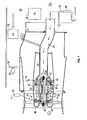
- FIG. 1 An exemplary air unit 10 for use in an aircraft is illustrated in FIG. 1 .
- the unit 10 includes a fan rotor 12 supporting rotor blades 14.
- An electric motor 16 rotatably drives the fan rotor 12.
- the motor 16 is arranged in a motor housing 18, and an inlet housing 20 is secured to the motor housing 18.
- the inlet housing 20 provides a heat exchanger inlet 22 for supplying air to the rotor blades 14.
- the inlet 22 receives air from a ram air duct 23.
- the rotor blades 14 pull atmospheric air through a heat exchanger 24 (shown schematically) and discharge the air overboard.
- the motor 16 includes a stator 32 arranged within the motor housing 18 that produces a magnetic field, which generates heat, causing the fan rotor 12 to rotate.
- the fan rotor 12 is supported by a thrust bearing 36 and journal bearings 38 arranged on either end of the fan rotor 12, in the example shown.
- a passage 40 is in fluid communication with the heat exchanger inlet 22 and provides cooling fluid to a cooling inlet 42 that is in fluid communication with the interior of the motor housing 18.
- a vent 44 is provided in the motor housing 18 that is in fluid communication with the heat exchanger outlet.
- the heat exchanger inlet 22 is on a high pressure side H
- the vent 44 is on a low pressure side L.
- the vent 44 is fluidly connected to an outlet 50 arranged in the ram air duct 23.
- the pressure differential between the high and low pressure sides H and L moves cooling fluid through the motor cooling inlet 42 to cool the stator 32, as indicated by the flow path M.
- a reverse J-tube 48 is provided on the high pressure side H of the ram air duct 23.
- the reverse J-tube 48 filters the air from the ram air duct 23.
- a passage 49 fluidly connects the reverse J-tube 48 to the cooling inlet 42. Clean cooling fluid flows from the reverse J-tube on the high pressure side H into the bearings 36, 38 and motor 16 and out the vent 44 on the low pressure side L. As a result, pressurized air from a source, such as engine bleed air for example, is not needed to provide cooling flow.
- the cooling fluid flows through the motor housing 18 to cool the bearings 36, 38 and motor 16 as indicated by flow path B.
- the outlet 50 is downstream of the fan rotor 56 driven by an electric motor 54 arranged within the ram air duct 23.
- the inlet 22 may be arranged upstream from a heat exchanger 52 within the ram air duct 23 and before the fan 56.
- the heat exchanger 52, electric motor 54, and fan 56 may be part of an air conditioning pack.
- the first reverse J-tube 48 may be disposed within the inlet housing 20 and the second reverse J-tube 48' may be located on the opposite side of wall 70 within the ram air duct 23.
- the air within the ram air duct 23 flows in a direction indicated by arrow F.
- a portion of the air from the ram air duct 23 enters the inlet housing 20 and travels along passage 40 to an inlet 22 of a heat exchanger 24 (illustrated schematically with dotted lines).
- a portion of the air travelling along passage 40 is drawn into a cool fluid flowpath, in a direction indicated by arrow C, at the first end 80 of the first reverse J-tube 48.
- Air drawn into the cooling fluid flowpath C travels in a direction opposite the airflow F within the ram air duct 23.
- FIG. 3 is a detailed view of the first reverse J-tube 48 positioned within the inlet housing 20.
- the particle separator 90 includes a plurality of generally uniform holes 92 sized to allow air, but not light foreign objects, to travel along the cool fluid flowpath C through the particle separator 90 and into the reverse J-tube 48.
- the particle separator 90 acts a filter, preventing particles larger than 5 micron from entering the first reverse J-tube 48.
- the shape of the particle separator 90 uses the airflow F within the ram air duct 23 to "clean" the exterior of the particle separator 90.
- the particle separator 90 is generally conical in shape, and the portion of the particle separator 90 having the greatest diameter is mounted to the first end 80 of the first reverse J-tube 48.
- the angle ⁇ of the particle separator 90 may be in the range of between about 25 and 35 degrees. In one embodiment, the angle ⁇ is 30 degrees.
- the force of the airflow F along passage 40, in the direction opposite the cooling fluid flowpath C, will remove foreign objects or debris from the surface of the particle separator 90.
- the airflow F along passage 40 eliminates any potential blockages that may inhibit air from flowing into the first end 80 of the reverse J-tube 48.
- first end 94 of the particle separator 90 may be welded to the first end 94 of the first reverse J-tube 48.
- fasteners may be used to retain the particle separator 90 in position relative to the first end 80 of the first reverse J-tube 48.
Landscapes
- Engineering & Computer Science (AREA)
- Chemical & Material Sciences (AREA)
- Combustion & Propulsion (AREA)
- Mechanical Engineering (AREA)
- General Engineering & Computer Science (AREA)
- Physics & Mathematics (AREA)
- Thermal Sciences (AREA)
- Motor Or Generator Cooling System (AREA)
- Aerodynamic Tests, Hydrodynamic Tests, Wind Tunnels, And Water Tanks (AREA)
Applications Claiming Priority (1)
| Application Number | Priority Date | Filing Date | Title |
|---|---|---|---|
| US13/525,836 US20140202121A1 (en) | 2012-06-18 | 2012-06-18 | Conical light fod momentum particle separator protector |
Publications (2)
| Publication Number | Publication Date |
|---|---|
| EP2677140A2 true EP2677140A2 (fr) | 2013-12-25 |
| EP2677140A3 EP2677140A3 (fr) | 2016-12-21 |
Family
ID=48182739
Family Applications (1)
| Application Number | Title | Priority Date | Filing Date |
|---|---|---|---|
| EP13164328.0A Withdrawn EP2677140A3 (fr) | 2012-06-18 | 2013-04-18 | Lumière conique pour protecteur de séparateur de trajectoire de particules |
Country Status (3)
| Country | Link |
|---|---|
| US (1) | US20140202121A1 (fr) |
| EP (1) | EP2677140A3 (fr) |
| JP (1) | JP5961583B2 (fr) |
Cited By (3)
| Publication number | Priority date | Publication date | Assignee | Title |
|---|---|---|---|---|
| EP2937288A1 (fr) * | 2014-04-25 | 2015-10-28 | Hamilton Sundstrand Corporation | Conception de tube d'entrée |
| EP2746588A3 (fr) * | 2012-12-19 | 2017-07-05 | Hamilton Sundstrand Corporation | Filtre à débris pour l'admission de refroidissement de moteur sur un ventilateur d'air dynamique |
| EP3415432A1 (fr) * | 2017-06-12 | 2018-12-19 | Hamilton Sundstrand Corporation | Enveloppe de tube en forme de j |
Families Citing this family (6)
| Publication number | Priority date | Publication date | Assignee | Title |
|---|---|---|---|---|
| US9192882B2 (en) * | 2009-09-03 | 2015-11-24 | Game Changers Llc | Apparatus and methods using non-fouling bypass filter |
| US9719352B2 (en) * | 2014-12-17 | 2017-08-01 | Honeywell International Inc. | Compartment based inlet particle separator system |
| US10472072B2 (en) * | 2015-11-25 | 2019-11-12 | Hamilton Sundstrand Corporation | Supply tube for sensor |
| US10252805B2 (en) * | 2016-01-06 | 2019-04-09 | Hamilton Sundstrand Corporation | Flow duct for a ram outlet header |
| US10265707B2 (en) | 2016-12-21 | 2019-04-23 | Hamilton Sundstrand Corporation | Motor cooling circuit with integrated FOD particle separator |
| US11090600B2 (en) | 2017-01-04 | 2021-08-17 | General Electric Company | Particle separator assembly for a turbine engine |
Family Cites Families (8)
| Publication number | Priority date | Publication date | Assignee | Title |
|---|---|---|---|---|
| GB1201096A (en) * | 1966-11-15 | 1970-08-05 | United Aircraft Corp | Air particle separator |
| US3871844A (en) * | 1973-09-28 | 1975-03-18 | Sr Frank F Calvin | Screen apparatus for air inlet |
| FR2642662B1 (fr) * | 1989-02-09 | 1992-04-30 | Abg Semca | Dispositif et procede de separation des particules solides presentes dans un gaz et appareil comportant un tel dispositif |
| US6994738B2 (en) * | 2003-05-28 | 2006-02-07 | Hamilton Sundstrand | Snow filter |
| JP4461180B2 (ja) * | 2004-09-22 | 2010-05-12 | ハミルトン・サンドストランド・コーポレイション | モーター冷却経路およびスラストベアリング負荷設計 |
| US7559965B2 (en) * | 2005-01-25 | 2009-07-14 | Samsung Gwangju Electronics Co., Ltd. | Cyclonic separating apparatus for vacuum cleaner which is capable of separately collecting water from dust |
| US7691162B2 (en) * | 2006-10-03 | 2010-04-06 | Mccahill Bill | Spike air filter apparatus and method |
| US8679210B2 (en) * | 2012-01-17 | 2014-03-25 | Hamilton Sundstrand Corporation | Shrouded particle separator |
-
2012
- 2012-06-18 US US13/525,836 patent/US20140202121A1/en not_active Abandoned
-
2013
- 2013-04-18 EP EP13164328.0A patent/EP2677140A3/fr not_active Withdrawn
- 2013-04-18 JP JP2013087044A patent/JP5961583B2/ja active Active
Non-Patent Citations (1)
| Title |
|---|
| None |
Cited By (7)
| Publication number | Priority date | Publication date | Assignee | Title |
|---|---|---|---|---|
| EP2746588A3 (fr) * | 2012-12-19 | 2017-07-05 | Hamilton Sundstrand Corporation | Filtre à débris pour l'admission de refroidissement de moteur sur un ventilateur d'air dynamique |
| US10072664B2 (en) | 2012-12-19 | 2018-09-11 | Hamilton Sundstrand Corporation | Debris filter for motor cooling inlet on ram air fan |
| EP2937288A1 (fr) * | 2014-04-25 | 2015-10-28 | Hamilton Sundstrand Corporation | Conception de tube d'entrée |
| US9759236B2 (en) | 2014-04-25 | 2017-09-12 | Hamilton Sundstrand Corporation | Inlet tube design |
| US10641294B2 (en) | 2014-04-25 | 2020-05-05 | Hamilton Sundstrand Corporation | Inlet tube design |
| EP3415432A1 (fr) * | 2017-06-12 | 2018-12-19 | Hamilton Sundstrand Corporation | Enveloppe de tube en forme de j |
| US10259588B2 (en) | 2017-06-12 | 2019-04-16 | Hamilton Sundstrand Corporation | J-tube shroud |
Also Published As
| Publication number | Publication date |
|---|---|
| JP5961583B2 (ja) | 2016-08-02 |
| US20140202121A1 (en) | 2014-07-24 |
| JP2014000947A (ja) | 2014-01-09 |
| EP2677140A3 (fr) | 2016-12-21 |
Similar Documents
| Publication | Publication Date | Title |
|---|---|---|
| EP2677140A2 (fr) | Lumière conique pour protecteur de séparateur de trajectoire de particules | |
| US8679210B2 (en) | Shrouded particle separator | |
| EP3369470B1 (fr) | Séparateur de particules inertiel pour machine à cycle d'air | |
| US10641294B2 (en) | Inlet tube design | |
| US9719352B2 (en) | Compartment based inlet particle separator system | |
| CN105980029A (zh) | 空气净化装置及方法 | |
| EP3339175B1 (fr) | Circuit de refroidissement de moteur avec séparateur de particules de dommage par corps étranger | |
| US9989070B2 (en) | Air cycle machine strut plate assembly | |
| EP2787198B1 (fr) | Prérefroidisseur pour moteur d'avion avec un orifice de prélèvement d'écoulement inverse exempt des contaminants | |
| US9764267B2 (en) | Air cleaner and air conditioner having air-cleaning function | |
| US9914542B2 (en) | Ram air fan housing | |
| US9347455B2 (en) | Ejector assembly | |
| JP5432887B2 (ja) | エアクリーナを含む強制空気開放通気システム及び、電気機械 | |
| CN103216394B (zh) | 风力发电塔强力送风除尘系统 | |
| CN102688805A (zh) | 用于从空气流中移除水分的系统 | |
| US11415022B2 (en) | Oil console equipment, rotary machine provided with oil console equipment, and method for recovering lubrication oil contained in exhaust gas | |
| EP3023330B1 (fr) | Ensemble échangeur de chaleur pour systèmes de contrôle de l'environnement (ecs) d'aéronef | |
| EP3192740B1 (fr) | Dispositif à orifice de trou de vidange | |
| CN113167297B (zh) | 用于集成电动压缩机单元的惯性过滤器 | |
| CN105736407A (zh) | 冲压空气风扇壳体中的排水孔 | |
| HK1180243A1 (zh) | 用於分离在空气流中带动的颗粒的空气抽吸装置和方法 | |
| HK1180243B (en) | Air extraction device and method for removing particles carried by an air flow |
Legal Events
| Date | Code | Title | Description |
|---|---|---|---|
| PUAI | Public reference made under article 153(3) epc to a published international application that has entered the european phase |
Free format text: ORIGINAL CODE: 0009012 |
|
| AK | Designated contracting states |
Kind code of ref document: A2 Designated state(s): AL AT BE BG CH CY CZ DE DK EE ES FI FR GB GR HR HU IE IS IT LI LT LU LV MC MK MT NL NO PL PT RO RS SE SI SK SM TR |
|
| AX | Request for extension of the european patent |
Extension state: BA ME |
|
| PUAL | Search report despatched |
Free format text: ORIGINAL CODE: 0009013 |
|
| AK | Designated contracting states |
Kind code of ref document: A3 Designated state(s): AL AT BE BG CH CY CZ DE DK EE ES FI FR GB GR HR HU IE IS IT LI LT LU LV MC MK MT NL NO PL PT RO RS SE SI SK SM TR |
|
| AX | Request for extension of the european patent |
Extension state: BA ME |
|
| RIC1 | Information provided on ipc code assigned before grant |
Ipc: F02C 7/055 20060101ALI20161111BHEP Ipc: F02C 7/05 20060101AFI20161111BHEP Ipc: F04D 29/70 20060101ALI20161111BHEP Ipc: F04D 25/08 20060101ALI20161111BHEP |
|
| STAA | Information on the status of an ep patent application or granted ep patent |
Free format text: STATUS: THE APPLICATION IS DEEMED TO BE WITHDRAWN |
|
| 18D | Application deemed to be withdrawn |
Effective date: 20170622 |