EP2677176A1 - Compresseur centrifuge électrique compact - Google Patents
Compresseur centrifuge électrique compact Download PDFInfo
- Publication number
- EP2677176A1 EP2677176A1 EP12305729.1A EP12305729A EP2677176A1 EP 2677176 A1 EP2677176 A1 EP 2677176A1 EP 12305729 A EP12305729 A EP 12305729A EP 2677176 A1 EP2677176 A1 EP 2677176A1
- Authority
- EP
- European Patent Office
- Prior art keywords
- axial
- electric compressor
- motor
- shaft
- radial
- Prior art date
- Legal status (The legal status is an assumption and is not a legal conclusion. Google has not performed a legal analysis and makes no representation as to the accuracy of the status listed.)
- Granted
Links
Images


Classifications
-
- F—MECHANICAL ENGINEERING; LIGHTING; HEATING; WEAPONS; BLASTING
- F04—POSITIVE - DISPLACEMENT MACHINES FOR LIQUIDS; PUMPS FOR LIQUIDS OR ELASTIC FLUIDS
- F04D—NON-POSITIVE-DISPLACEMENT PUMPS
- F04D25/00—Pumping installations or systems
- F04D25/02—Units comprising pumps and their driving means
- F04D25/06—Units comprising pumps and their driving means the pump being electrically driven
- F04D25/0606—Units comprising pumps and their driving means the pump being electrically driven the electric motor being specially adapted for integration in the pump
-
- F—MECHANICAL ENGINEERING; LIGHTING; HEATING; WEAPONS; BLASTING
- F04—POSITIVE - DISPLACEMENT MACHINES FOR LIQUIDS; PUMPS FOR LIQUIDS OR ELASTIC FLUIDS
- F04D—NON-POSITIVE-DISPLACEMENT PUMPS
- F04D25/00—Pumping installations or systems
- F04D25/02—Units comprising pumps and their driving means
- F04D25/06—Units comprising pumps and their driving means the pump being electrically driven
- F04D25/0606—Units comprising pumps and their driving means the pump being electrically driven the electric motor being specially adapted for integration in the pump
- F04D25/0653—Units comprising pumps and their driving means the pump being electrically driven the electric motor being specially adapted for integration in the pump the motor having a plane air gap, e.g. disc-type
-
- F—MECHANICAL ENGINEERING; LIGHTING; HEATING; WEAPONS; BLASTING
- F04—POSITIVE - DISPLACEMENT MACHINES FOR LIQUIDS; PUMPS FOR LIQUIDS OR ELASTIC FLUIDS
- F04D—NON-POSITIVE-DISPLACEMENT PUMPS
- F04D29/00—Details, component parts, or accessories
- F04D29/05—Shafts or bearings, or assemblies thereof, specially adapted for elastic fluid pumps
- F04D29/056—Bearings
- F04D29/058—Bearings magnetic; electromagnetic
-
- F—MECHANICAL ENGINEERING; LIGHTING; HEATING; WEAPONS; BLASTING
- F16—ENGINEERING ELEMENTS AND UNITS; GENERAL MEASURES FOR PRODUCING AND MAINTAINING EFFECTIVE FUNCTIONING OF MACHINES OR INSTALLATIONS; THERMAL INSULATION IN GENERAL
- F16C—SHAFTS; FLEXIBLE SHAFTS; ELEMENTS OR CRANKSHAFT MECHANISMS; ROTARY BODIES OTHER THAN GEARING ELEMENTS; BEARINGS
- F16C32/00—Bearings not otherwise provided for
- F16C32/04—Bearings not otherwise provided for using magnetic or electric supporting means
- F16C32/0406—Magnetic bearings
- F16C32/044—Active magnetic bearings
- F16C32/0474—Active magnetic bearings for rotary movement
- F16C32/0493—Active magnetic bearings for rotary movement integrated in an electrodynamic machine, e.g. self-bearing motor
- F16C32/0495—Active magnetic bearings for rotary movement integrated in an electrodynamic machine, e.g. self-bearing motor generating torque and axial force
-
- F—MECHANICAL ENGINEERING; LIGHTING; HEATING; WEAPONS; BLASTING
- F16—ENGINEERING ELEMENTS AND UNITS; GENERAL MEASURES FOR PRODUCING AND MAINTAINING EFFECTIVE FUNCTIONING OF MACHINES OR INSTALLATIONS; THERMAL INSULATION IN GENERAL
- F16C—SHAFTS; FLEXIBLE SHAFTS; ELEMENTS OR CRANKSHAFT MECHANISMS; ROTARY BODIES OTHER THAN GEARING ELEMENTS; BEARINGS
- F16C32/00—Bearings not otherwise provided for
- F16C32/04—Bearings not otherwise provided for using magnetic or electric supporting means
- F16C32/0406—Magnetic bearings
- F16C32/044—Active magnetic bearings
- F16C32/0474—Active magnetic bearings for rotary movement
- F16C32/0493—Active magnetic bearings for rotary movement integrated in an electrodynamic machine, e.g. self-bearing motor
- F16C32/0497—Active magnetic bearings for rotary movement integrated in an electrodynamic machine, e.g. self-bearing motor generating torque and radial force
-
- F—MECHANICAL ENGINEERING; LIGHTING; HEATING; WEAPONS; BLASTING
- F16—ENGINEERING ELEMENTS AND UNITS; GENERAL MEASURES FOR PRODUCING AND MAINTAINING EFFECTIVE FUNCTIONING OF MACHINES OR INSTALLATIONS; THERMAL INSULATION IN GENERAL
- F16C—SHAFTS; FLEXIBLE SHAFTS; ELEMENTS OR CRANKSHAFT MECHANISMS; ROTARY BODIES OTHER THAN GEARING ELEMENTS; BEARINGS
- F16C2360/00—Engines or pumps
- F16C2360/44—Centrifugal pumps
-
- F—MECHANICAL ENGINEERING; LIGHTING; HEATING; WEAPONS; BLASTING
- F16—ENGINEERING ELEMENTS AND UNITS; GENERAL MEASURES FOR PRODUCING AND MAINTAINING EFFECTIVE FUNCTIONING OF MACHINES OR INSTALLATIONS; THERMAL INSULATION IN GENERAL
- F16C—SHAFTS; FLEXIBLE SHAFTS; ELEMENTS OR CRANKSHAFT MECHANISMS; ROTARY BODIES OTHER THAN GEARING ELEMENTS; BEARINGS
- F16C2380/00—Electrical apparatus
- F16C2380/26—Dynamo-electric machines or combinations therewith, e.g. electro-motors and generators
Definitions
- the present invention relates to a compact electric centrifugal compressor which is more specifically but not exclusively adapted to be used in a Heat Ventilation Air Conditioning (HVAC) installation for vehicles.
- HVAC Heat Ventilation Air Conditioning
- the vehicles may include in particular terrestrial vehicles such as hybrid electric vehicles (HEV) or electric vehicles (EV) as well as aircrafts or other kinds of vehicles.
- terrestrial vehicles such as hybrid electric vehicles (HEV) or electric vehicles (EV) as well as aircrafts or other kinds of vehicles.
- HEV hybrid electric vehicles
- EV electric vehicles
- HVAC compressors for vehicles are typically associated with an electric motor.
- HVAC electric compressors Two main categories of HVAC electric compressors are used in HEV/EV vehicles: rotary like vane compressors and oscillating like scroll type compressors.
- the invention is intended more especially, although not exclusively, to automotive air conditioning applications and therefore further aims at providing an electric compressor which takes into account the high level of vibrations generated in a vehicle and which is as compact as possible.
- a compact electric compressor comprising a motor portion and a centrifugal compressor portion driven by said motor portion through a shaft
- said motor portion comprises first and second radial bearingless motors spaced apart along said shaft and configured for rotating said shaft and maintaining it in a defined radial position in a contactless manner during functional operation of said electric compressor and axial electromagnetic means located between said first and second radial bearingless motors and configured for maintaining said shaft in a defined axial position during functional operation of said electric compressor and wherein auxiliary landing bearing are located at each end of the shaft in the vicinity of each of said first and second radial bearingless motors.
- the axial electromagnetic means comprise an axial bearingless motor.
- the axial electromagnetic means comprise an active axial magnetic bearing.
- Separators may be provided between the radial bearingless motors and the axial electromagnetic means.
- the radial bearingless motors each comprise a rotor portion having a plurality of pole pairs armatures and a stator portion comprising a core with slots for receiving windings configured to impress a motor torque and a radial bearing force.
- Separate windings may be provided in the slots of the stator portion for impressing a motor torque and an axial bearing force.
- common windings may be provided in the slots of the stator portion for impressing a motor torque and an axial bearing force.
- the radial bearingless motors comprise a rotor portion chosen among an induction rotor, a permanent magnet rotor, a hysteresis rotor and a reluctance rotor.
- the centrifugal compressor portion comprises a wheel at a first end of the shaft and control circuits associated with the radial bearingless motors and the axial electromagnetic means are located at a second end of the shaft and are connected to the radial bearingless motors and the axial electromagnetic means via a feedthrough.
- the centrifugal compressor portion may comprise a variety of configurations and in particular may comprise a single wheel, double wheels, tandem wheels or double tandem wheels.
- the axial bearingless motor may comprise a rotor portion having a plurality of pole pairs armatures and first and second stator portions each comprising a core with slots respectively for receiving windings configured to impress a motor torque and an axial bearing force, the first and second stator portions being located on each side of the rotor portion.
- said active axial magnetic bearing may comprise a disc armature integral with the shaft and first and second stator electromagnets facing said disc armature in a contactless manner on each side of the latter.
- FIG. 2 shows an example of a centrifugal electric compressor for heat ventilation air conditioning (HVAC) which may be dedicated for hybrid electric vehicles (HEV) or electric vehicles (EV) or else for aircrafts or other types of vehicles.
- HVAC heat ventilation air conditioning
- HEV hybrid electric vehicles
- EV electric vehicles
- Such centrifugal electric compressor may also be applied to boost a turbocharger.
- a rotor shaft 15 of a motor portion 20 is coupled to a centrifugal compressor wheel 11 of a compressor portion 10 to drive the centrifugal compressor wheel 11.
- An electrical motor 30 comprises a rotor 31 which may be of any type chosen among induction rotor, permanent magnet rotor, hysteresis rotor and reluctance rotor.
- the electrical motor 30 further comprises a stator 32 with windings 32a.
- First and second active radial magnetic bearings 40, 50 are located on each side of the electrical motor 30 to support the shaft 15 in levitation during functional operation of the electric compressor.
- Each active radial magnetic bearing 40, 50 comprises a rotor 41, 51 fast with the shaft 15 and a stator 42, 52 with windings 42a, 52a.
- An active axial magnetic bearing 60 (thrust bearing) comprises on the one hand a disc 61 which is mounted perpendicular to the axis of the shaft 15 and constitutes a rotor armature and on the other hand first and second stators 62, 63 each having at least one annular coil or winding 62a, 63a located in a stator 62, 63 which may have a C-shaped core, as shown in figure 2 .
- each stator 62, 63 could have an E-shaped core with two coils.
- the radial bearing rotors 41, 51 are equipped with ferromagnetic laminations which are held in position by the magnetic fields created by the electromagnets of the stators 42, 52.
- the shaft 15 is levitated in a contactless manner due to the radial magnetic bearings.
- the shaft's position is monitored by sensors (not shown), e.g. of the variable inductive type, which detect any deviation from nominal position and emit signals which are used in a control system (not shown in figure 2 ) to command currents in the windings 42a, 52a of the radial bearings in order to bring the shaft 15 back to its nominal position.
- the axial bearing 60 is based on the same principle and sensors (not shown) send signals to a controller to adjust command currents in the coils 62a, 63a of the axial bearing 60 to adjust the axial position of the shaft 15.
- Auxiliary landing bearings 8 are used for supporting the shaft 15 essentially during a starting or stopping operation of the motor portion 20, but also during brief intermittent periods in case of shock-loads due to the usually high level of vibrations present in a vehicle.
- auxiliary bearings also known as emergency bearings, are provided in order to support the shaft while the machine is being stopped or in the event of a total or partial failure of the magnetic suspension, thereby preventing direct contact between the magnetic circuits of the rotors and the stators of the magnetic bearings or bearingless motors when the windings of the stator electromagnets are not properly powered, thus avoiding damage to the laminations thereof.
- auxiliary bearings leave clearance about the rotary shaft and do not themselves rotate.
- the clearance provided for the auxiliary bearings is generally about one half the width of the air gap of the magnetic bearings or bearingless motors.
- the auxiliary landing/touch down bearings 8 may have a variety of designs and may be for example rolling bearings, needle bearings, plain bearings, bushings, etc...
- Separators 9 may be located between the stator windings of the magnetic bearings 40, 50, 60 and of the electrical motor 30.
- the axial bearing 60 comprises a disc armature 61 and two stators 62, 63 located at an end of the shaft 15, whereas the compressor wheel is located at the other end of the shaft.
- the axial bearing 60 can also be located on the same side than the compressor wheel 11.
- control circuits 70 comprising a variable frequency drive 71 and amplifiers 72 associated with the electrical motor 30 and the radial electromagnetic bearings 40, 50, 60 are integrated in a flange and located at a second end of the iron shaft 15.
- the control circuits 70 are connected to the electrical motor 30 and to the radial and axial electromagnetic bearings via a feedthrough 74.
- a connector 73 serves to connect the control circuits 70 to a further controller located remote from the electric compressor.
- Figure 3 shows an embodiment which is similar to the embodiment of figure 2 , but the axial magnetic bearing is split into two parts 60A, 60B which are located at both ends of the shaft 15.
- a disc armature 61A integral with the shaft 15 is located at a first end of the shaft 15 near the compressor wheel 11 and cooperates with a first stator 62 having a first coil 62a which could be similar to the stator 62 of figure 1 .
- a disc armature 61B integral with the shaft 15 is located at a second end of the shaft 15 and cooperates with a second stator 63 having a second coil 63a which could be similar to the stator 63 of figure 2 .
- FIGS 1 to 3 show a compressor portion 10 having a single wheel. However other designs of the compressor portion 10 may be used in combination with the different embodiments disclosed herein.
- a compressor portion 10 may include double wheels 11, 13.
- a compressor portion 10A, 10B may include tandem wheels 11, 12.
- a compressor portion 10A, 10B may include double tandem wheels 11, 13, 12, 14.
- the configurations of compressor wheels according to figures 7 to 9 are intended either to increase the pressure ratio or to increase the flow.
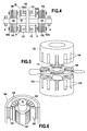
- Figure 4 shows an embodiment with an iron shaft 15 and a motor portion 20 which are more compact than the embodiments of figures 1 to 3 since the electrical motor 30 and the radial magnetic bearings 40, 50 are replaced by first and second radial bearingless motors 140, 150.
- the compressor portion 10 has been omitted but may be realized as previously described with reference to figures 1 to 3 and 7 to 9 .
- figure 4 allows reducing the shaft length and hence improves the overall layout.
- the radial bearingless motors 140, 150 each comprise a disc-like central armature 141, 151 integral with the shaft 15 and a stator 142, 152 with windings 142a, 152a.
- radial bearingless motor 180 is represented in figure 6 .
- Such radial bearingless motor 180 comprises a rotor 181 integral with the shaft 15 and a stator 182 with slots 184 for receiving coils 185.
- the rotor 181 carries different structural elements 183 depending on the chosen principle (permanent magnet, induction, switched reluctance, hysteresis).
- stator windings 185 achieve both functions of torque windings and suspension force windings.
- torque windings As an example if two magnetic fields, which may be created by two winding sets with a difference in the pole pair number of one, are superposed, a torque and a radial force will be produced. It is thus possible for example to combine a 4-pole motor winding of a reluctance motor with a 2-pole bearing winding, but many other embodiments are possible.
- Patent document US 6727618 B1 discloses an example of bearingless switched reluctance motor.
- stator portions 142, 152, 182 of the radial bearingless motors 140, 150, 180 separated coils may be used to impress the bearing force and the motor torque.
- the needed bearing force and motor torque may be generated in each coil by combined windings.
- a single coil will carry jointly the required motor and bearing ampere-turns.
- reference numeral 130 may designate an axial bearingless motor as well as an axial active magnetic bearing.
- the disc armature 131 and the stator portions 132, 133 with windings 132a and 133a respectively may be constituted like the thrust bearing 60 illustrated in figure 2 , i.e. the windings 132a, 133a would be constituted by annular coils centered on the axis of the shaft 15.
- the axial magnetic bearing 130 could also comprise stator portions 132, 133 having a C-shape with a single annular coil 132a, 133a as shown in figure 4 or having an E-shape with two concentric annular coils.
- FIG. 4 may also designate an axial bearingless motor.
- the embodiment of figure 4 comprises first and second radial bearingless motors 140, 150 and a central axial bearingless motor located between the first and second radial bearingless motors 140, 150.
- the axial bearingless motor 130 also comprises a disc armature 131 integral with the shaft 15 and first and second stator portions 132, 133 located on each side of the disc armature 131, but the windings 132a and 133a are differently arranged.
- Figure 5 shows in perspective an example of a possible configuration of an axial bearingless motor 130.
- the axial bearingless motor 130 of figure 5 comprises a rotor portion 131 having a plurality of pole pairs armatures 138 and first and second stator portions 132, 133 each comprising a core with slots 134, 135 respectively for receiving windings (not shown in figure 5 ) configured to impress a motor torque and an axial bearing force, the first and second stator portions 132, 133 being located on each side of the rotor portion 131.
- stator portions 132, 133 of the axial bearingless motor separated coils may be used to impress the bearing force and the motor torque.
- the needed bearing force and motor torque may be generated in each coil by combined windings.
- a single coil will carry jointly the required motor and bearing ampere-turns.
- a plurality of pole pairs armatures 138 are shown in figure 5 by way of example.
- the rotor 131 may carry different structural elements depending on the chosen principle (permanent magnet, induction, switched reluctance, hysteresis).
- the stator 132 and the rotor 131 with permanent magnets 138 may constitute a permanent magnet motor, where the permanent magnets 138 on the rotor surface produce an axial force in a first direction (upward direction in the configuration of figure 5 ), whereas the stator 133 and rotor 131 may constitute a synchronous reluctance motor, where the winding currents of the synchronous reluctance motor produce an adjustable axial force in the opposite direction with respect to the first direction (downward direction in the configuration of figure 5 ).
- the axial position of the rotor can thus be controlled by the currents of the synchronous motor.
- other combinations of motor types may be chosen as soon as the axial bearingless motor 130 achieves the two functions of impressing a motor torque and an axial bearing force.
- Active radial magnetic bearings 140 and 150 similar to previously described active radial magnetic bearings 40 and 50 and comprising a rotor armature 141, 151 and a stator 142, 152 with windings 142a, 152a may be located on each side of an axial bearingless motor 130.
- first and second radial bearingless motors 140, 150 are preferably used in combination with an axial bearingless motor 130 or a thrust magnetic bearing.
Landscapes
- Engineering & Computer Science (AREA)
- General Engineering & Computer Science (AREA)
- Mechanical Engineering (AREA)
- Physics & Mathematics (AREA)
- Electromagnetism (AREA)
- Connection Of Motors, Electrical Generators, Mechanical Devices, And The Like (AREA)
- Structures Of Non-Positive Displacement Pumps (AREA)
Priority Applications (4)
| Application Number | Priority Date | Filing Date | Title |
|---|---|---|---|
| EP12305729.1A EP2677176B1 (fr) | 2012-06-22 | 2012-06-22 | Compresseur centrifuge électrique compact |
| CA2820446A CA2820446C (fr) | 2012-06-22 | 2013-06-20 | Compresseur centrifuge electrique destine aux vehicules |
| JP2013130342A JP6194194B2 (ja) | 2012-06-22 | 2013-06-21 | コンパクト電動遠心コンプレッサー |
| CN201310251461.1A CN103758766A (zh) | 2012-06-22 | 2013-06-24 | 紧凑型电动离心压缩机 |
Applications Claiming Priority (1)
| Application Number | Priority Date | Filing Date | Title |
|---|---|---|---|
| EP12305729.1A EP2677176B1 (fr) | 2012-06-22 | 2012-06-22 | Compresseur centrifuge électrique compact |
Publications (2)
| Publication Number | Publication Date |
|---|---|
| EP2677176A1 true EP2677176A1 (fr) | 2013-12-25 |
| EP2677176B1 EP2677176B1 (fr) | 2018-12-19 |
Family
ID=46465164
Family Applications (1)
| Application Number | Title | Priority Date | Filing Date |
|---|---|---|---|
| EP12305729.1A Active EP2677176B1 (fr) | 2012-06-22 | 2012-06-22 | Compresseur centrifuge électrique compact |
Country Status (4)
| Country | Link |
|---|---|
| EP (1) | EP2677176B1 (fr) |
| JP (1) | JP6194194B2 (fr) |
| CN (1) | CN103758766A (fr) |
| CA (1) | CA2820446C (fr) |
Cited By (17)
| Publication number | Priority date | Publication date | Assignee | Title |
|---|---|---|---|---|
| EP2918845A1 (fr) | 2014-03-11 | 2015-09-16 | Skf Magnetic Mechatronics | Machine rotative, roulement et procédé de fabrication d'une machine rotative |
| EP3118976A1 (fr) | 2015-07-17 | 2017-01-18 | Universite Catholique De Louvain | Machine électrique comportant un palier électrodynamique radial |
| DE102016004714A1 (de) * | 2016-04-19 | 2017-10-19 | Saurer Germany Gmbh & Co. Kg | Spinnrotorschaft, Lageranordnung zum aktiven magnetischen Lagern eines solchen Spinnrotorschafts und Spinnrotorantriebseinrichtung |
| WO2018043797A1 (fr) * | 2016-08-30 | 2018-03-08 | 엘지전자 주식회사 | Compresseur et système refroidisseur comprenant ledit compresseur |
| WO2018175938A1 (fr) * | 2017-03-24 | 2018-09-27 | Johnson Controls Technology Company | Compresseur de moteur à palier magnétique |
| WO2018211101A1 (fr) | 2017-05-19 | 2018-11-22 | Universite Catholique De Louvain | Machine électrique ayant un palier électrodynamique axial |
| WO2019133725A1 (fr) * | 2017-12-29 | 2019-07-04 | Johnson Controls Technology Company | Placement de palier de butée pour compresseur |
| WO2020103520A1 (fr) * | 2018-11-21 | 2020-05-28 | 珠海格力电器股份有限公司 | Structure de palier de suspension magnétique et structure de compresseur à suspension magnétique |
| EP3542079A4 (fr) * | 2016-11-17 | 2020-09-02 | Baker Hughes, a GE company, LLC | Palier de butée magnétique actif pour commande de rotation lente d'arbre |
| EP3579390A4 (fr) * | 2017-05-09 | 2020-12-02 | Daikin Industries, Ltd. | Turbocompresseur |
| US10895282B2 (en) | 2016-08-18 | 2021-01-19 | Daikin Industries, Ltd. | Magnetic bearing device and fluid mechanical system |
| CN112771759A (zh) * | 2018-08-03 | 2021-05-07 | 先进电机有限公司 | 电气子组件和相关联的操作方法 |
| CN112865421A (zh) * | 2020-12-21 | 2021-05-28 | 山东大学 | 一种五自由度单绕组无轴承磁悬浮电机 |
| CN114109861A (zh) * | 2021-11-25 | 2022-03-01 | 海德韦尔(太仓)能源科技有限公司 | 一种空压机推力轴承布置结构 |
| CN114251359A (zh) * | 2021-11-19 | 2022-03-29 | 青岛海尔空调电子有限公司 | 压缩机及制冷系统 |
| CN115217844A (zh) * | 2021-04-19 | 2022-10-21 | 青岛海特生物医疗有限公司 | 一种离心机 |
| CN116155008A (zh) * | 2023-03-16 | 2023-05-23 | 哈尔滨工业大学 | 一种极限环境自然磁悬浮开关磁阻储能飞轮电机 |
Families Citing this family (20)
| Publication number | Priority date | Publication date | Assignee | Title |
|---|---|---|---|---|
| CN105656285A (zh) * | 2014-11-11 | 2016-06-08 | 中国科学院沈阳科学仪器股份有限公司 | 一种可有效防止磁场对轴承寿命影响的磁力传动器 |
| CN104481898B (zh) * | 2014-12-05 | 2017-01-04 | 浙江理工大学 | 采用电磁轴承的外转子轴流风机 |
| WO2016137775A1 (fr) | 2015-02-26 | 2016-09-01 | Carrier Corporation | Palier magnétique |
| ES2897273T3 (es) | 2017-04-01 | 2022-02-28 | Carrier Corp | Rodamiento magnético radial con refuerzo de flujo |
| WO2018182891A1 (fr) | 2017-04-01 | 2018-10-04 | Carrier Corporation | Palier magnétique radial à amplification de flux |
| CN110462234B (zh) | 2017-04-01 | 2022-05-31 | 开利公司 | 具有磁通升高的磁径向轴承、使用磁轴承的方法以及机器 |
| CN108869540B (zh) * | 2018-01-12 | 2024-06-25 | 刘慕华 | 一种推力轴承、转子系统及推力轴承的控制方法 |
| CN108869541B (zh) * | 2018-01-12 | 2024-04-02 | 刘慕华 | 一种径向轴承、转子系统及径向轴承的控制方法 |
| US10280850B1 (en) | 2018-01-23 | 2019-05-07 | Ford Global Technologies, Llc | Double-ended electric supercharger |
| JP2019210899A (ja) * | 2018-06-07 | 2019-12-12 | 株式会社豊田自動織機 | 遠心圧縮機 |
| CN109026997A (zh) * | 2018-09-19 | 2018-12-18 | 张枫 | 一种可靠性高的磁悬浮轴承 |
| CN109340258A (zh) * | 2018-11-21 | 2019-02-15 | 珠海格力电器股份有限公司 | 一种新型永磁电动磁悬浮轴承结构 |
| CN109611350B (zh) * | 2018-11-26 | 2020-08-25 | 振欣透平机械有限公司 | 一种磁悬浮氯气透平压缩机 |
| CN111486112A (zh) * | 2019-01-29 | 2020-08-04 | 青岛海尔智能技术研发有限公司 | 磁悬浮离心压缩机及空调系统 |
| CN109780059A (zh) * | 2019-03-07 | 2019-05-21 | 苏州赛得尔智能科技有限公司 | 一种四自由度直线电机用磁悬浮轴承 |
| KR102292394B1 (ko) * | 2020-02-25 | 2021-08-23 | 엘지전자 주식회사 | 압축기 |
| WO2022222563A1 (fr) * | 2021-04-19 | 2022-10-27 | 青岛海尔生物医疗科技有限公司 | Centrifugeuse |
| CN113819072B (zh) * | 2021-10-18 | 2023-08-22 | 杭州旋速科技有限公司 | 一种涡扇磁悬浮管道风机 |
| JP7381976B2 (ja) * | 2022-03-28 | 2023-11-16 | ダイキン工業株式会社 | スラスト磁気軸受のロータ、スラスト磁気軸受、および回転式流体機械 |
| CN117703927B (zh) * | 2024-02-05 | 2024-04-16 | 贵州中航华强科技有限公司 | 一种磁悬浮轴承控制系统 |
Citations (5)
| Publication number | Priority date | Publication date | Assignee | Title |
|---|---|---|---|---|
| JPH08326530A (ja) * | 1995-05-31 | 1996-12-10 | Koyo Seiko Co Ltd | エアポンプ |
| US6183215B1 (en) | 1998-05-25 | 2001-02-06 | Denso Corporation | Electric motor driven compressor |
| US6727618B1 (en) | 2002-06-10 | 2004-04-27 | The United States Of America, As Represented By The Administrator Of National Aeronautics And Space Administration | Bearingless switched reluctance motor |
| US20090121571A1 (en) * | 2007-10-18 | 2009-05-14 | Iwaki Co., Ltd. | Magnetic levitation motor and pump |
| EP2234243A1 (fr) * | 2008-01-24 | 2010-09-29 | Tokyo University Of Science Educational Foundation Administrative Organization | Moteur sans roulement |
Family Cites Families (12)
| Publication number | Priority date | Publication date | Assignee | Title |
|---|---|---|---|---|
| JPS5471310A (en) * | 1977-11-16 | 1979-06-07 | Shin Meiwa Ind Co Ltd | Variable speed induction motor |
| FR2528127A1 (fr) * | 1982-06-04 | 1983-12-09 | Creusot Loire | Moto-compresseur centrifuge electrique integre a grande vitesse |
| JPS631340A (ja) * | 1986-06-20 | 1988-01-06 | Nippon Seiko Kk | 非接触支持モ−タ装置 |
| JPS6455031A (en) * | 1987-08-26 | 1989-03-02 | Nippon Seiko Kk | Magnetic bearing motor |
| JPH0332338A (ja) * | 1989-06-26 | 1991-02-12 | Shimadzu Corp | モーター体型磁気軸受 |
| IL109967A (en) * | 1993-06-15 | 1997-07-13 | Multistack Int Ltd | Compressor |
| FR2817088B1 (fr) * | 2000-11-17 | 2003-02-21 | Mecanique Magnetique Sa | Machine tournante a butee axiale magnetique integrant une generatrice de courant |
| CA2373905A1 (fr) * | 2002-02-28 | 2003-08-28 | Ronald David Conry | Compresseur centrifuge double |
| JP5247045B2 (ja) * | 2007-02-22 | 2013-07-24 | サンデン株式会社 | インバータ一体型電動圧縮機の製造方法 |
| US8847450B2 (en) * | 2007-03-08 | 2014-09-30 | General Electric Company | Encapsulated magnet assembly and process for making |
| US20090113999A1 (en) * | 2007-03-08 | 2009-05-07 | General Electric Company | Method for Testing a Rotor and Stator Assembly |
| US7847454B2 (en) * | 2007-03-08 | 2010-12-07 | General Electric Company | Encapsulated stator assembly and process for making |
-
2012
- 2012-06-22 EP EP12305729.1A patent/EP2677176B1/fr active Active
-
2013
- 2013-06-20 CA CA2820446A patent/CA2820446C/fr active Active
- 2013-06-21 JP JP2013130342A patent/JP6194194B2/ja active Active
- 2013-06-24 CN CN201310251461.1A patent/CN103758766A/zh active Pending
Patent Citations (5)
| Publication number | Priority date | Publication date | Assignee | Title |
|---|---|---|---|---|
| JPH08326530A (ja) * | 1995-05-31 | 1996-12-10 | Koyo Seiko Co Ltd | エアポンプ |
| US6183215B1 (en) | 1998-05-25 | 2001-02-06 | Denso Corporation | Electric motor driven compressor |
| US6727618B1 (en) | 2002-06-10 | 2004-04-27 | The United States Of America, As Represented By The Administrator Of National Aeronautics And Space Administration | Bearingless switched reluctance motor |
| US20090121571A1 (en) * | 2007-10-18 | 2009-05-14 | Iwaki Co., Ltd. | Magnetic levitation motor and pump |
| EP2234243A1 (fr) * | 2008-01-24 | 2010-09-29 | Tokyo University Of Science Educational Foundation Administrative Organization | Moteur sans roulement |
Cited By (32)
| Publication number | Priority date | Publication date | Assignee | Title |
|---|---|---|---|---|
| US10260557B2 (en) | 2014-03-11 | 2019-04-16 | Skf Magnetic Mechatronics | Rotary machine, bearing and method for manufacturing a rotary machine |
| EP2918845A1 (fr) | 2014-03-11 | 2015-09-16 | Skf Magnetic Mechatronics | Machine rotative, roulement et procédé de fabrication d'une machine rotative |
| EP3118976A1 (fr) | 2015-07-17 | 2017-01-18 | Universite Catholique De Louvain | Machine électrique comportant un palier électrodynamique radial |
| DE102016004714A1 (de) * | 2016-04-19 | 2017-10-19 | Saurer Germany Gmbh & Co. Kg | Spinnrotorschaft, Lageranordnung zum aktiven magnetischen Lagern eines solchen Spinnrotorschafts und Spinnrotorantriebseinrichtung |
| US10473157B2 (en) | 2016-04-19 | 2019-11-12 | Saurer Spinning Solutions Gmbh & Co. Kg | Spinning rotor shaft, bearing arrangement for the active magnetic support of such a spinning rotor shaft and spinning rotor drive device |
| US10895282B2 (en) | 2016-08-18 | 2021-01-19 | Daikin Industries, Ltd. | Magnetic bearing device and fluid mechanical system |
| WO2018043797A1 (fr) * | 2016-08-30 | 2018-03-08 | 엘지전자 주식회사 | Compresseur et système refroidisseur comprenant ledit compresseur |
| US10962020B2 (en) | 2016-08-30 | 2021-03-30 | Lg Electronics Inc. | Compressor and chiller system including same |
| CN109642584B (zh) * | 2016-08-30 | 2021-07-02 | Lg电子株式会社 | 压缩机以及包括其的制冷系统 |
| CN109642584A (zh) * | 2016-08-30 | 2019-04-16 | Lg电子株式会社 | 压缩机以及包括其的制冷系统 |
| EP3508732A4 (fr) * | 2016-08-30 | 2020-04-15 | LG Electronics Inc. -1- | Compresseur et système refroidisseur comprenant ledit compresseur |
| EP3542079A4 (fr) * | 2016-11-17 | 2020-09-02 | Baker Hughes, a GE company, LLC | Palier de butée magnétique actif pour commande de rotation lente d'arbre |
| WO2018175938A1 (fr) * | 2017-03-24 | 2018-09-27 | Johnson Controls Technology Company | Compresseur de moteur à palier magnétique |
| EP4098884A1 (fr) * | 2017-03-24 | 2022-12-07 | Johnson Controls Tyco IP Holdings LLP | Compresseur de moteur à palier magnétique |
| US10666113B2 (en) | 2017-03-24 | 2020-05-26 | Johnson Controls Technology Company | Magnetic bearing motor compressor |
| CN110475977B (zh) * | 2017-03-24 | 2022-04-26 | 江森自控科技公司 | 磁性轴承马达压缩机 |
| CN110475977A (zh) * | 2017-03-24 | 2019-11-19 | 江森自控科技公司 | 磁性轴承马达压缩机 |
| US11757328B2 (en) | 2017-03-24 | 2023-09-12 | Johnson Controls Tyco IP Holdings LLP | Magnetic bearing motor compressor |
| EP3579390A4 (fr) * | 2017-05-09 | 2020-12-02 | Daikin Industries, Ltd. | Turbocompresseur |
| US11971045B2 (en) | 2017-05-09 | 2024-04-30 | Daikin Industries, Ltd. | Turbo compressor |
| WO2018211101A1 (fr) | 2017-05-19 | 2018-11-22 | Universite Catholique De Louvain | Machine électrique ayant un palier électrodynamique axial |
| WO2019133725A1 (fr) * | 2017-12-29 | 2019-07-04 | Johnson Controls Technology Company | Placement de palier de butée pour compresseur |
| CN112771759A (zh) * | 2018-08-03 | 2021-05-07 | 先进电机有限公司 | 电气子组件和相关联的操作方法 |
| US11466731B2 (en) | 2018-11-21 | 2022-10-11 | Gree Electric Appliances, Inc. Of Zhuhai | Magnetic levitation bearing structure and magnetic levitation compressor structure |
| WO2020103520A1 (fr) * | 2018-11-21 | 2020-05-28 | 珠海格力电器股份有限公司 | Structure de palier de suspension magnétique et structure de compresseur à suspension magnétique |
| CN112865421A (zh) * | 2020-12-21 | 2021-05-28 | 山东大学 | 一种五自由度单绕组无轴承磁悬浮电机 |
| CN112865421B (zh) * | 2020-12-21 | 2024-04-09 | 山东大学 | 一种五自由度单绕组无轴承磁悬浮电机 |
| CN115217844A (zh) * | 2021-04-19 | 2022-10-21 | 青岛海特生物医疗有限公司 | 一种离心机 |
| CN114251359A (zh) * | 2021-11-19 | 2022-03-29 | 青岛海尔空调电子有限公司 | 压缩机及制冷系统 |
| CN114251359B (zh) * | 2021-11-19 | 2024-06-07 | 青岛海尔空调电子有限公司 | 压缩机及制冷系统 |
| CN114109861A (zh) * | 2021-11-25 | 2022-03-01 | 海德韦尔(太仓)能源科技有限公司 | 一种空压机推力轴承布置结构 |
| CN116155008A (zh) * | 2023-03-16 | 2023-05-23 | 哈尔滨工业大学 | 一种极限环境自然磁悬浮开关磁阻储能飞轮电机 |
Also Published As
| Publication number | Publication date |
|---|---|
| CA2820446C (fr) | 2019-10-15 |
| EP2677176B1 (fr) | 2018-12-19 |
| CN103758766A (zh) | 2014-04-30 |
| JP2014007951A (ja) | 2014-01-16 |
| CA2820446A1 (fr) | 2013-12-22 |
| JP6194194B2 (ja) | 2017-09-06 |
Similar Documents
| Publication | Publication Date | Title |
|---|---|---|
| EP2677176B1 (fr) | Compresseur centrifuge électrique compact | |
| EP2677177B1 (fr) | Compresseur centrifuge électrique pour véhicules | |
| US9863431B2 (en) | Hybrid magnetic suspension of a rotor | |
| JP4274423B2 (ja) | 車両用車輪において一体化された電動モータ | |
| EP2784326B1 (fr) | Turbomachine compact à paliers magnétiques et paliers auxiliaires | |
| US20040022653A1 (en) | Rotary machine with axial stop incorporating a current generator | |
| US11300131B2 (en) | Electric motor system and turbo compressor provided therewith | |
| MX2013011852A (es) | Sistemas y metodos de control de espacio de aire. | |
| US10208759B2 (en) | Compact turbomachine with magnetic bearings and auxiliary bearings | |
| US20100123364A1 (en) | Substantially parallel flux uncluttered rotor machines | |
| US4197474A (en) | Hermetic clutch | |
| JP3850195B2 (ja) | 磁気浮上モータ | |
| EP4303440A1 (fr) | Moteur électrique, compresseur et dispositif de réfrigération | |
| EP3780380B1 (fr) | Système de moteur électrique et turbocompresseur équipé de ce dernier | |
| WO2018063820A1 (fr) | Turbomachine à paliers magnétiques actifs | |
| CN112088487A (zh) | 电动机系统及包括该电动机系统的涡轮压缩机 | |
| RU2540696C1 (ru) | Высокоскоростная электрическая машина с вертикальным валом | |
| US20240003357A1 (en) | Centrifugal compressor for refrigeration system and refrigeration system | |
| EP4299931A1 (fr) | Système de moteur électrique, turbocompresseur et dispositif de réfrigération | |
| CN216929758U (zh) | 一种电机的轴向磁轴承结构及磁悬浮高速电机 | |
| CN214412425U (zh) | 磁悬浮径向轴承定子、径向轴承、压缩机、空调器 | |
| EP4226062B1 (fr) | Accouplement extensible avec un couvercle et une disposition électromécanique avec un tel accouplement | |
| KR20250166933A (ko) | 회전자 및 전기 기계 | |
| CN119196175A (zh) | 一种主动式磁悬浮轴承以及电励磁磁通切换电机 | |
| CN105896863A (zh) | 混合励磁发电机与真空泵集成装置 |
Legal Events
| Date | Code | Title | Description |
|---|---|---|---|
| PUAI | Public reference made under article 153(3) epc to a published international application that has entered the european phase |
Free format text: ORIGINAL CODE: 0009012 |
|
| AK | Designated contracting states |
Kind code of ref document: A1 Designated state(s): AL AT BE BG CH CY CZ DE DK EE ES FI FR GB GR HR HU IE IS IT LI LT LU LV MC MK MT NL NO PL PT RO RS SE SI SK SM TR |
|
| AX | Request for extension of the european patent |
Extension state: BA ME |
|
| 17P | Request for examination filed |
Effective date: 20140625 |
|
| RBV | Designated contracting states (corrected) |
Designated state(s): AL AT BE BG CH CY CZ DE DK EE ES FI FR GB GR HR HU IE IS IT LI LT LU LV MC MK MT NL NO PL PT RO RS SE SI SK SM TR |
|
| RIC1 | Information provided on ipc code assigned before grant |
Ipc: F16C 32/04 20060101ALI20180607BHEP Ipc: F04D 25/06 20060101AFI20180607BHEP Ipc: F04D 29/058 20060101ALI20180607BHEP |
|
| GRAP | Despatch of communication of intention to grant a patent |
Free format text: ORIGINAL CODE: EPIDOSNIGR1 |
|
| STAA | Information on the status of an ep patent application or granted ep patent |
Free format text: STATUS: GRANT OF PATENT IS INTENDED |
|
| INTG | Intention to grant announced |
Effective date: 20180720 |
|
| GRAS | Grant fee paid |
Free format text: ORIGINAL CODE: EPIDOSNIGR3 |
|
| GRAA | (expected) grant |
Free format text: ORIGINAL CODE: 0009210 |
|
| STAA | Information on the status of an ep patent application or granted ep patent |
Free format text: STATUS: THE PATENT HAS BEEN GRANTED |
|
| AK | Designated contracting states |
Kind code of ref document: B1 Designated state(s): AL AT BE BG CH CY CZ DE DK EE ES FI FR GB GR HR HU IE IS IT LI LT LU LV MC MK MT NL NO PL PT RO RS SE SI SK SM TR |
|
| REG | Reference to a national code |
Ref country code: GB Ref legal event code: FG4D |
|
| REG | Reference to a national code |
Ref country code: CH Ref legal event code: EP |
|
| REG | Reference to a national code |
Ref country code: IE Ref legal event code: FG4D |
|
| REG | Reference to a national code |
Ref country code: DE Ref legal event code: R096 Ref document number: 602012054813 Country of ref document: DE |
|
| REG | Reference to a national code |
Ref country code: AT Ref legal event code: REF Ref document number: 1079029 Country of ref document: AT Kind code of ref document: T Effective date: 20190115 |
|
| REG | Reference to a national code |
Ref country code: NL Ref legal event code: MP Effective date: 20181219 |
|
| PG25 | Lapsed in a contracting state [announced via postgrant information from national office to epo] |
Ref country code: BG Free format text: LAPSE BECAUSE OF FAILURE TO SUBMIT A TRANSLATION OF THE DESCRIPTION OR TO PAY THE FEE WITHIN THE PRESCRIBED TIME-LIMIT Effective date: 20190319 Ref country code: LT Free format text: LAPSE BECAUSE OF FAILURE TO SUBMIT A TRANSLATION OF THE DESCRIPTION OR TO PAY THE FEE WITHIN THE PRESCRIBED TIME-LIMIT Effective date: 20181219 Ref country code: LV Free format text: LAPSE BECAUSE OF FAILURE TO SUBMIT A TRANSLATION OF THE DESCRIPTION OR TO PAY THE FEE WITHIN THE PRESCRIBED TIME-LIMIT Effective date: 20181219 Ref country code: NO Free format text: LAPSE BECAUSE OF FAILURE TO SUBMIT A TRANSLATION OF THE DESCRIPTION OR TO PAY THE FEE WITHIN THE PRESCRIBED TIME-LIMIT Effective date: 20190319 Ref country code: HR Free format text: LAPSE BECAUSE OF FAILURE TO SUBMIT A TRANSLATION OF THE DESCRIPTION OR TO PAY THE FEE WITHIN THE PRESCRIBED TIME-LIMIT Effective date: 20181219 Ref country code: FI Free format text: LAPSE BECAUSE OF FAILURE TO SUBMIT A TRANSLATION OF THE DESCRIPTION OR TO PAY THE FEE WITHIN THE PRESCRIBED TIME-LIMIT Effective date: 20181219 |
|
| REG | Reference to a national code |
Ref country code: LT Ref legal event code: MG4D |
|
| REG | Reference to a national code |
Ref country code: AT Ref legal event code: MK05 Ref document number: 1079029 Country of ref document: AT Kind code of ref document: T Effective date: 20181219 |
|
| PG25 | Lapsed in a contracting state [announced via postgrant information from national office to epo] |
Ref country code: AL Free format text: LAPSE BECAUSE OF FAILURE TO SUBMIT A TRANSLATION OF THE DESCRIPTION OR TO PAY THE FEE WITHIN THE PRESCRIBED TIME-LIMIT Effective date: 20181219 Ref country code: GR Free format text: LAPSE BECAUSE OF FAILURE TO SUBMIT A TRANSLATION OF THE DESCRIPTION OR TO PAY THE FEE WITHIN THE PRESCRIBED TIME-LIMIT Effective date: 20190320 Ref country code: SE Free format text: LAPSE BECAUSE OF FAILURE TO SUBMIT A TRANSLATION OF THE DESCRIPTION OR TO PAY THE FEE WITHIN THE PRESCRIBED TIME-LIMIT Effective date: 20181219 Ref country code: RS Free format text: LAPSE BECAUSE OF FAILURE TO SUBMIT A TRANSLATION OF THE DESCRIPTION OR TO PAY THE FEE WITHIN THE PRESCRIBED TIME-LIMIT Effective date: 20181219 |
|
| PG25 | Lapsed in a contracting state [announced via postgrant information from national office to epo] |
Ref country code: NL Free format text: LAPSE BECAUSE OF FAILURE TO SUBMIT A TRANSLATION OF THE DESCRIPTION OR TO PAY THE FEE WITHIN THE PRESCRIBED TIME-LIMIT Effective date: 20181219 |
|
| PG25 | Lapsed in a contracting state [announced via postgrant information from national office to epo] |
Ref country code: PT Free format text: LAPSE BECAUSE OF FAILURE TO SUBMIT A TRANSLATION OF THE DESCRIPTION OR TO PAY THE FEE WITHIN THE PRESCRIBED TIME-LIMIT Effective date: 20190419 Ref country code: IT Free format text: LAPSE BECAUSE OF FAILURE TO SUBMIT A TRANSLATION OF THE DESCRIPTION OR TO PAY THE FEE WITHIN THE PRESCRIBED TIME-LIMIT Effective date: 20181219 Ref country code: PL Free format text: LAPSE BECAUSE OF FAILURE TO SUBMIT A TRANSLATION OF THE DESCRIPTION OR TO PAY THE FEE WITHIN THE PRESCRIBED TIME-LIMIT Effective date: 20181219 Ref country code: ES Free format text: LAPSE BECAUSE OF FAILURE TO SUBMIT A TRANSLATION OF THE DESCRIPTION OR TO PAY THE FEE WITHIN THE PRESCRIBED TIME-LIMIT Effective date: 20181219 Ref country code: CZ Free format text: LAPSE BECAUSE OF FAILURE TO SUBMIT A TRANSLATION OF THE DESCRIPTION OR TO PAY THE FEE WITHIN THE PRESCRIBED TIME-LIMIT Effective date: 20181219 |
|
| PG25 | Lapsed in a contracting state [announced via postgrant information from national office to epo] |
Ref country code: EE Free format text: LAPSE BECAUSE OF FAILURE TO SUBMIT A TRANSLATION OF THE DESCRIPTION OR TO PAY THE FEE WITHIN THE PRESCRIBED TIME-LIMIT Effective date: 20181219 Ref country code: SM Free format text: LAPSE BECAUSE OF FAILURE TO SUBMIT A TRANSLATION OF THE DESCRIPTION OR TO PAY THE FEE WITHIN THE PRESCRIBED TIME-LIMIT Effective date: 20181219 Ref country code: IS Free format text: LAPSE BECAUSE OF FAILURE TO SUBMIT A TRANSLATION OF THE DESCRIPTION OR TO PAY THE FEE WITHIN THE PRESCRIBED TIME-LIMIT Effective date: 20190419 Ref country code: RO Free format text: LAPSE BECAUSE OF FAILURE TO SUBMIT A TRANSLATION OF THE DESCRIPTION OR TO PAY THE FEE WITHIN THE PRESCRIBED TIME-LIMIT Effective date: 20181219 Ref country code: SK Free format text: LAPSE BECAUSE OF FAILURE TO SUBMIT A TRANSLATION OF THE DESCRIPTION OR TO PAY THE FEE WITHIN THE PRESCRIBED TIME-LIMIT Effective date: 20181219 |
|
| REG | Reference to a national code |
Ref country code: DE Ref legal event code: R097 Ref document number: 602012054813 Country of ref document: DE |
|
| PLBE | No opposition filed within time limit |
Free format text: ORIGINAL CODE: 0009261 |
|
| STAA | Information on the status of an ep patent application or granted ep patent |
Free format text: STATUS: NO OPPOSITION FILED WITHIN TIME LIMIT |
|
| PG25 | Lapsed in a contracting state [announced via postgrant information from national office to epo] |
Ref country code: DK Free format text: LAPSE BECAUSE OF FAILURE TO SUBMIT A TRANSLATION OF THE DESCRIPTION OR TO PAY THE FEE WITHIN THE PRESCRIBED TIME-LIMIT Effective date: 20181219 Ref country code: AT Free format text: LAPSE BECAUSE OF FAILURE TO SUBMIT A TRANSLATION OF THE DESCRIPTION OR TO PAY THE FEE WITHIN THE PRESCRIBED TIME-LIMIT Effective date: 20181219 |
|
| 26N | No opposition filed |
Effective date: 20190920 |
|
| REG | Reference to a national code |
Ref country code: DE Ref legal event code: R119 Ref document number: 602012054813 Country of ref document: DE |
|
| PG25 | Lapsed in a contracting state [announced via postgrant information from national office to epo] |
Ref country code: MC Free format text: LAPSE BECAUSE OF FAILURE TO SUBMIT A TRANSLATION OF THE DESCRIPTION OR TO PAY THE FEE WITHIN THE PRESCRIBED TIME-LIMIT Effective date: 20181219 |
|
| REG | Reference to a national code |
Ref country code: CH Ref legal event code: PL |
|
| GBPC | Gb: european patent ceased through non-payment of renewal fee |
Effective date: 20190622 |
|
| PG25 | Lapsed in a contracting state [announced via postgrant information from national office to epo] |
Ref country code: SI Free format text: LAPSE BECAUSE OF FAILURE TO SUBMIT A TRANSLATION OF THE DESCRIPTION OR TO PAY THE FEE WITHIN THE PRESCRIBED TIME-LIMIT Effective date: 20181219 |
|
| REG | Reference to a national code |
Ref country code: BE Ref legal event code: MM Effective date: 20190630 |
|
| PG25 | Lapsed in a contracting state [announced via postgrant information from national office to epo] |
Ref country code: TR Free format text: LAPSE BECAUSE OF FAILURE TO SUBMIT A TRANSLATION OF THE DESCRIPTION OR TO PAY THE FEE WITHIN THE PRESCRIBED TIME-LIMIT Effective date: 20181219 |
|
| PG25 | Lapsed in a contracting state [announced via postgrant information from national office to epo] |
Ref country code: DE Free format text: LAPSE BECAUSE OF NON-PAYMENT OF DUE FEES Effective date: 20200101 Ref country code: IE Free format text: LAPSE BECAUSE OF NON-PAYMENT OF DUE FEES Effective date: 20190622 Ref country code: GB Free format text: LAPSE BECAUSE OF NON-PAYMENT OF DUE FEES Effective date: 20190622 |
|
| PG25 | Lapsed in a contracting state [announced via postgrant information from national office to epo] |
Ref country code: BE Free format text: LAPSE BECAUSE OF NON-PAYMENT OF DUE FEES Effective date: 20190630 Ref country code: LI Free format text: LAPSE BECAUSE OF NON-PAYMENT OF DUE FEES Effective date: 20190630 Ref country code: CH Free format text: LAPSE BECAUSE OF NON-PAYMENT OF DUE FEES Effective date: 20190630 Ref country code: LU Free format text: LAPSE BECAUSE OF NON-PAYMENT OF DUE FEES Effective date: 20190622 |
|
| PG25 | Lapsed in a contracting state [announced via postgrant information from national office to epo] |
Ref country code: CY Free format text: LAPSE BECAUSE OF FAILURE TO SUBMIT A TRANSLATION OF THE DESCRIPTION OR TO PAY THE FEE WITHIN THE PRESCRIBED TIME-LIMIT Effective date: 20181219 |
|
| PG25 | Lapsed in a contracting state [announced via postgrant information from national office to epo] |
Ref country code: MT Free format text: LAPSE BECAUSE OF FAILURE TO SUBMIT A TRANSLATION OF THE DESCRIPTION OR TO PAY THE FEE WITHIN THE PRESCRIBED TIME-LIMIT Effective date: 20181219 Ref country code: HU Free format text: LAPSE BECAUSE OF FAILURE TO SUBMIT A TRANSLATION OF THE DESCRIPTION OR TO PAY THE FEE WITHIN THE PRESCRIBED TIME-LIMIT; INVALID AB INITIO Effective date: 20120622 |
|
| PG25 | Lapsed in a contracting state [announced via postgrant information from national office to epo] |
Ref country code: MK Free format text: LAPSE BECAUSE OF FAILURE TO SUBMIT A TRANSLATION OF THE DESCRIPTION OR TO PAY THE FEE WITHIN THE PRESCRIBED TIME-LIMIT Effective date: 20181219 |
|
| P01 | Opt-out of the competence of the unified patent court (upc) registered |
Effective date: 20230514 |
|
| PGFP | Annual fee paid to national office [announced via postgrant information from national office to epo] |
Ref country code: FR Payment date: 20250624 Year of fee payment: 14 |