EP2679083A1 - Mähvorrichtung - Google Patents
Mähvorrichtung Download PDFInfo
- Publication number
- EP2679083A1 EP2679083A1 EP12173872.8A EP12173872A EP2679083A1 EP 2679083 A1 EP2679083 A1 EP 2679083A1 EP 12173872 A EP12173872 A EP 12173872A EP 2679083 A1 EP2679083 A1 EP 2679083A1
- Authority
- EP
- European Patent Office
- Prior art keywords
- lawn mower
- recharging
- module
- target value
- cable
- Prior art date
- Legal status (The legal status is an assumption and is not a legal conclusion. Google has not performed a legal analysis and makes no representation as to the accuracy of the status listed.)
- Granted
Links
Images




Classifications
-
- A—HUMAN NECESSITIES
- A01—AGRICULTURE; FORESTRY; ANIMAL HUSBANDRY; HUNTING; TRAPPING; FISHING
- A01D—HARVESTING; MOWING
- A01D34/00—Mowers; Mowing apparatus of harvesters
- A01D34/006—Control or measuring arrangements
- A01D34/008—Control or measuring arrangements for automated or remotely controlled operation
-
- G—PHYSICS
- G05—CONTROLLING; REGULATING
- G05D—SYSTEMS FOR CONTROLLING OR REGULATING NON-ELECTRIC VARIABLES
- G05D1/00—Control of position, course, altitude or attitude of land, water, air or space vehicles, e.g. using automatic pilots
- G05D1/02—Control of position or course in two dimensions
- G05D1/021—Control of position or course in two dimensions specially adapted to land vehicles
- G05D1/0212—Control of position or course in two dimensions specially adapted to land vehicles with means for defining a desired trajectory
- G05D1/0225—Control of position or course in two dimensions specially adapted to land vehicles with means for defining a desired trajectory involving docking at a fixed facility, e.g. base station or loading bay
-
- G—PHYSICS
- G05—CONTROLLING; REGULATING
- G05D—SYSTEMS FOR CONTROLLING OR REGULATING NON-ELECTRIC VARIABLES
- G05D1/00—Control of position, course, altitude or attitude of land, water, air or space vehicles, e.g. using automatic pilots
- G05D1/02—Control of position or course in two dimensions
- G05D1/021—Control of position or course in two dimensions specially adapted to land vehicles
- G05D1/0259—Control of position or course in two dimensions specially adapted to land vehicles using magnetic or electromagnetic means
- G05D1/0265—Control of position or course in two dimensions specially adapted to land vehicles using magnetic or electromagnetic means using buried wires
Definitions
- the present invention relates to an apparatus for cutting grass.
- the lawn mowers are used to maintain lawns, gardens and grassy areas in general, in optimum conditions, i.e. to maintain the grass below a certain height in a substantially homogenous manner in the entire cutting area.
- the cutting area is often bounded by a wire or perimeter cable, in which an electric signal is propagated; by detecting this electric signal the lawn mower is able to recognise the boundaries of the cutting area and to consequently regulate movement and/or cutting activities.
- the lawn mowers are provided with an independent electric supplying unit that has the task of supplying electric energy to the electric devices and electromechanical devices inside the lawn mower, such as, for example, the motors intended for moving the wheels and the blades, the electronic circuits dedicated to detecting the presence of grass, to detecting the presence of the perimeter cable, to processing the detected data and to controlling the various motors, etc.
- an independent electric supplying unit that has the task of supplying electric energy to the electric devices and electromechanical devices inside the lawn mower, such as, for example, the motors intended for moving the wheels and the blades, the electronic circuits dedicated to detecting the presence of grass, to detecting the presence of the perimeter cable, to processing the detected data and to controlling the various motors, etc.
- the lawn mower goes to a recharging base, where the supplying unit can be recharged in such a manner as to enable the lawn mower to continue to operate, after a certain time.
- This independent electric supplying unit enables the lawn mower to move along the cutting area, change movement direction when approaching an obstacle and/or to follow a set cutting path or return to the base.
- the lawn mower During normal cutting operations, the lawn mower meets different types of obstacle, such as stones, unevenness in the terrain, boundary walls; each time the lawn mower meets an obstacle it has to change direction; even the recharging base can often constitute an obstacle to the passage of the lawn mower, determining an obligatory change of direction and potential damage due to the collision of the lawn mower and the base.
- obstacle such as stones, unevenness in the terrain, boundary walls
- the lawn mower in operation is provided with blades designed for cutting grass; further, the lawn mower is normally equipped with recharging means in the front part.
- the object of the present invention is to provide an apparatus for cutting grass that is improved in terms of resistance to damage of the components thereof.
- another object of the present invention is to provide an apparatus for cutting grass in which the recharging means is safeguarded as far as possible.
- Another object of the present invention is to provide an apparatus for cutting grass in which the cutting means is as far as possible immune to damage.
- the apparatus 100 ( figure 1 ) comprises a lawn mower 1, set up to operate at least inside a cutting area S, bounded by a perimeter cable 2.
- the lawn mower 1 ( figures 2-3 ) comprises above all a frame 10; the frame 10 can comprise, for example, an upper case 10a and a lower case 10b, preferably removably associated together.
- the upper case 10a and the lower case 10b can be made, for example, of plastic.
- the lawn mower 1 further comprises movement means 20 mounted on the frame 10 to move the lawn mower 1 with respect to the cutting area S; the latter can be a lawn, a garden, a flowerbed, or in general any surface on which the lawn mower 1 is called to operate.
- the movement means 20 preferably comprises a plurality of wheels 20a, fitted to the frame 10, and one or more motors, that are set up to rotate these wheels 20a.
- the lawn mower 1 shown in the attached figures is provided with four suitably driven wheels 20a.
- the lawn mower 1 further comprises one or more blades 30 (shown schematically in figure 3 ), fitted to the frame 10, to cut the grass in the cutting area S.
- the blades 30 are moved by suitable motors housed inside the frame 10.
- the aforesaid motors can be electric motors, supplied by a battery; the latter can be of the rechargeable type.
- recharging takes place on a recharging base 80.
- the recharging base 80 is positioned outside the cutting area (S).
- the recharging base 80 is positioned outside the perimeter cable 2.
- the technical effect determined by this feature is that the base is less "intrusive" and bulky for the lawn mower.
- the recharging base does not hinder the movement of the lawn mower and at the same time the recharging base cannot be damaged in any way by the blades of the lawn mower during normal cutting operations.
- the aforesaid battery can also supply a control unit (which will be disclosed below), and other electric/electronic devices provided on board the lawn mower 1.
- a control unit which will be disclosed below
- other electric/electronic devices provided on board the lawn mower 1.
- the apparatus 100 further comprises a management device 3 ( figure 1 ) associated with the aforesaid perimeter cable 2.
- the management device 3 is configured for supplying an output electric signal ES.
- the management device 3 is connected to the cable 2, such that the electric signal ES is propagated in the cable 2.
- the perimeter cable 2 is an electric cable.
- the electric signal ES can have the shape of a sine wave, a square wave, etc.
- the lawn mower 1 further comprises a control unit 60, which has the task of managing at least partially operation of the lawn mower.
- control unit 60 comprises sensor means 40 for detecting the electric signal ES that is propagated in the cable 2.
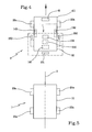
- the sensor means 40 can comprise a detecting element 41 ( fig.4 ), preferably consisting of an inductive element, such as, for example a reel.
- the sensor means 40 further comprises a current reader 42 and, possibly, a current amplifier 43 designed to permit improved reading of the detected signal.
- the detecting element 41 is fitted to the frame 10 in a front position thereof.
- the detecting element can be advantageously positioned in front of an axis X, which ideally, or also mechanically, joins the front wheels of the lawn mower 1 ( figure 4 ).
- control unit 60 manages the movement of the lawn mower 1.
- control unit 60 further comprises a memory 61 for storing a maximum value Vmax and a minimum value Vmin for a detecting intensity of said electric signal ES.
- Such maximum and minimum values Vmax, Vmin are relative to the intensity with which the sensor means 40 detects the electric signal ES.
- the maximum and minimum values Vmax, Vmin can be expressed in volt. Said maximum and minimum values Vmax, Vmin are respectively representative of a minimum distance Dmin and a maximum distance Dmax of the lawn mower 1 from the perimeter cable 2.
- Vmax, Vmin can be advantageously detected by the lawn mower 1, by the sensor means 40, during operation of the lawn mower 1. Alternatively, these values can be set.
- the control unit 60 further comprises a calculation module 62 associated with the aforesaid memory 61.
- the calculation module 62 is configured for determining a target value Tv for detecting the intensity of the electric signal ES.
- the target value Tv is not nil and is comprised between the maximum value Vmax and the minimum value Vmin.
- the target value Tv is representative of a target distance Td of the lawn mower 1 with respect to the perimeter cable 2.
- the calculation module 62 determines the target value Tv in such a manner as to determine correspondingly the target distance Td at which the lawn mower 1 will have to position itself in relation to the cable 2.
- the target value Tv is substantially different from a preceding target value determined by the detecting intensity of the same electric signal ES.
- the target value Tv is used for defining the method with which the lawn mower 1 approaches the recharging base 80 until it detects the first portion Q of electric cable 2 having the first conformation C1.
- the target value Tv is determined in such a manner that it takes on a different value for each work cycle, i.e. for each time in which the lawn mower 1 has to approach the recharging base 80.
- the target value Tv is determined in a random manner, by an algorithm that is able to generate random numbers comprised within the interval that have as limits the aforesaid maximum value Vmax and minimum value Vmin.
- the limits Vmax and/or Vmin can be excluded from the range of acceptable values.
- Vmin as limits a sub-interval can be selected within which the target value Tv is calculated.
- the target value Tv is determined according to a set sequence of values, for example cyclically.
- the control unit 60 further comprises an operating module 63 configured for controlling the movement means 20 to move the lawn mower 1 such that the sensor means 40 detects the electric signal ES at an intensity that is substantially equal to the target value Tv.
- the operating module 63 sends appropriate control signals to the movement means 20, such that, during the movement of the lawn mower 1, the intensity with which the sensor means 40 detects the electric signal ES is substantially equal to the target value Tv.
- the lawn mower 1 whilst it approaches the recharging base 80, is maintained at a distance from the perimeter cable 2 that is substantially equal to the aforesaid target distance Td.
- the operating module 63 preferably comprises a comparing module 63a configured for comparing the target value Tv with the intensity with which the electric signal ES is detected by the sensor means 40. In this manner it is possible to check whether the lawn mower 1 is moving at a correct distance (i.e. distance that is substantially equal to the target distance Td).
- the operating module 63 further comprises a control module 63b associated with the comparing module 63a and configured for controlling in a suitable manner the movement means 20 as a function of the comparison made by the comparing module 63a.
- a control module 63b associated with the comparing module 63a and configured for controlling in a suitable manner the movement means 20 as a function of the comparison made by the comparing module 63a.
- the corrections to the trajectory of the lawn mower 1 made by the control module 63b are preferably minimal, i.e. they do not involve sharp or excessively angular steering. This is because, for the purposes of approaching the recharging base 80, it is not indispensable to follow an extremely precise trajectory and it is necessary to assign greater importance to other factors (e.g. the possibility of moving the lawn mower 1 at a great speed and obtaining a quick return to the recharging base 80).
- the corrections to the trajectory of the lawn mower 1 made by the control module 63b involve curves having a radius of more than 0.70 metres and in particular the same as or greater than 1 metre.
- the corrections to the trajectory of the lawn mower 1 made by the control module 63b involve curves defining angles of less than 90°, and in particular angles of less than 70°.
- the comparing module 63a repeatedly compares the intensity with which the electric signal ES is detected and the target value Tv.
- this comparison can be made by maintaining a set interval between each comparison and the next.
- Said set interval can have a duration comprised between 1 second and 3 seconds.
- this duration can be substantially equal to 2 seconds.
- the electric signal ES is detected more frequently (i.e. more often than once every two seconds), for example every 0.1 seconds.
- An average for example an arithmetical average, is then made of the detected values and the result is compared with the target value Tv.
- the lawn mower 1 comprises a supplying unit 70.
- the supplying unit can comprise, for example, one or more batteries.
- the supplying unit 70 has the task of supplying electric power to the electric-electronic-electromechanical devices on the lawn mower 1.
- the supplying unit 70 can be recharged at the aforesaid recharging base 80.
- a monitoring circuit 71 is associated with the supplying unit 70.
- the monitoring circuit 71 is configured for monitoring the supplying unit 70, and in particular the charge level of the latter. When this level falls below a set threshold, the monitoring circuit generates an alert signal AS.
- the alert signal AS is sent to the control unit 60, so that the calculation module 62 and the operating module 63 are activatable as a function of the alert signal AS.
- the monitoring circuit 71 detects that the supplying unit 70 needs to be recharged, it reports this situation to the control unit 60; the calculation module 62, for determining the target value Tv, and the operating module 63, for consequent moving of the lawn mower 1 are thus activated, such that the lawn mower 1 can approach the recharging base 80 according to what has been established by the calculation module 62.
- the control unit 60 manages the return of the lawn mower to the recharging base 80.
- the perimeter cable 2 has a first portion Q having a set first conformation C1.
- the first portion Q has a first conformation C1 that is concave with respect to the perimeter defined by the perimeter cable 2.
- the first portion Q when it is detected by the lawn mower 1, enables the lawn mower 1 to adapt accordingly.
- control unit 60 comprises a first recognition module 164 ( fig. 3 ).
- the first recognition module 164 is configured for recognising the aforesaid first portion Q of the perimeter cable 2.
- the control unit 60 further comprises a first auxiliary module 165, configured for controlling the movement means 20 as a function of the recognition carried out by the first recognition module 164.
- the recognition module 164 is configured for determining, as a function of the electric signal ES propagating in the first portion Q, first main data MD1 that are representative of the first conformation C1 of the first portion Q of the cable 2.
- the first recognition module 164 can comprise a positioning circuit 164a connected to the sensor means 40 and configured for determining, during movement of the lawn mower 1, the position of the aforesaid detecting element 41 with respect to the cutting area S.
- the positioning circuit 164a depending on the detection of the electric signal ES by the detecting element 41, is able to determine whether the latter is at the first portion Q of the cable 2.
- the aforesaid first main data MD 1 can thus be determined as a function of a plurality of successive positions of the detecting element 41 with respect to the perimeter cable 2 during movement of the lawn mower 1.
- the first main data MD1 can comprise first data that are representative of the fact that the detecting element 41 is at the first portion Q of the cable 2.
- the first portion Q has a conformation that is such that it can be easily identified by a series of data of the type referring to the detecting element 41.
- the positioning circuit 164a supplies, with substantial continuity (i.e. preferably, at a set frequency) data that are representative of the position of the detecting element 41; in this sense first main data MD1 are to be considered to be representative of the first conformation C1 of the first portion Q of the perimeter cable 2, and as a function of these data it is thus possible to determine the presence of the first portion Q.
- the first recognition module 164 further comprises a comparison circuit 164b configured for comparing the first main data MD1 with first pre-stored reference data Ref1.
- the first reference data Ref1 which are stored in an appropriate first memory register 164c, are representative of the first reference conformation C1.
- the first reference data Ref1 are representative of the first conformation C1 of the first portion Q, stored beforehand in the lawn mower 1, such that the latter, and in particular the first recognition module 164, can recognise the first conformation C1 when it is detected by the sensor means 40.
- the first reference data Ref1 can comprise, in succession, data that are representative of the fact that the detecting element 41 is outside the cutting area S for a first path, and data that are representative of the fact that the detecting element 41 is inside the cutting area S for a second path after the first path.
- the detection by the sensor means 40 can be discrete, and be conducted at a set frequency (e.g. once every 0.1 seconds). Then, inside the first reference data Ref1, the data that are representative of the fact that the detecting element 41 is inside the cutting area S can consist of a certain number of discrete measurements in this sense (for example, twenty measurements).
- the data that are representative of the fact that the detecting element 41 is then outside the cutting area S can consist of a certain number of measurements in this sense (for example, five measurements).
- a first notification signal NS1 is generated.
- the first notification signal NS1 is thus indicative of the fact that the lawn mower 1 is at the first portion Q of the perimeter cable 2.
- the first notification signal NS1 is directed to the aforesaid first auxiliary module 165 so that the latter can control the movement means 20 in such a manner that the lawn mower 1 returns to the recharging base 80.
- the first auxiliary module 165 associated with the first recognition module 164, is configured for receiving the first notification signal NS1.
- the first auxiliary module 165 is further configured for controlling the movement means 20, following reception of this signal, such that the lawn mower 1, from a first position I near the first portion Q, is arranged in a direction d that is transverse to the cable 2 with a front part 411 facing the cutting area S; this latter position is indicated with II in figure 1 a.
- the front part 411 of the lawn mower 1 is defined as the part of the lawn mower in the lawn mower advancing direction.
- the lawn mower in the first position I near the first portion Q is substantially aligned on the perimeter cable 2.
- the first auxiliary module 165 is further configured for controlling the movement means 20 in such a manner as to make the lawn mower return along the direction d until it meets the recharging base 80.
- the lawn mower 1 comprises first recharging means 141 in the rear part thereof and the recharging base 80 comprises corresponding second recharging means 151 facing the first recharging means 141.
- the first 141 and second 151 means are configured for an operational coupling in the recharging base 80 during a recharging step.
- the lawn mower 1 comprises third recharging means 142, 143 on the lateral sides thereof ( fig. 4 ) and the recharging base 80 comprises corresponding fourth recharging means 152,153, facing the third recharging means 142, 143.
- the third 142,143 and fourth 152,153 recharging means are configured for an operational coupling in the recharging base 80 during a recharging step.
- the lawn mower 1 comprises fifth recharging means 144 on the upper part of the frame ( fig. 4 ) and the recharging base 80 comprises corresponding sixth recharging means 154 facing the fifth recharging means 144.
- the fifth 144 and sixth 154 recharging means are configured for operational coupling in the recharging base 80 during a recharging step.
- the recharging means comprises sliding contacts. In one embodiment of the invention, the recharging means is configured for a recharge by electric coupling, in particular of inductive type.
- the recharging base 80 comprises at least one first inductive element E1, and a first control unit 85 associated with the first inductive element E1 and configured for running a determined current Ic in the first inductive element E1.
- the lawn mower 1 comprises a second inductive element E2 associated with the supplying unit 70 and couplable with the first inductive element E1 for a recharge of the supplying unit 70.
- the lawn mower 1 comprises a second control unit 75 configured for:
- the first control unit 85 is configured for:
- the perimeter cable 2 has a second portion P having a set second conformation C2.
- the second portion P is shown schematically and by way of example shown in figure 1 .
- the second portion P has a concave conformation with respect to the perimeter defined by the perimeter cable 2.
- the second portion P has a substantially U-shaped conformation C2, such as to form a sort of recess of the perimeter of the cutting area S facing the interior of the cutting area S.
- the second portion P can have a substantially square second conformation C2, which is similar to the conformation defined by three sides of a rectangle (two larger sides and a lesser side).
- Part of cable 2 immediately adjacent to portion P can be comprised between 3 cm and 10 cm.
- the second portion P is useful because when it is detected by the lawn mower 1, it enables the lawn mower 1 to adapt accordingly.
- control unit 60 comprises a recognition module 64, which is suitable for recognising the aforesaid second portion P of the perimeter cable 2, and a second auxiliary module 65 that is suitable for controlling the movement means 20 as a function of the recognition carried out by the second recognition module 64.
- the second recognition module 64 is configured for determining, as a function of the electric signal ES propagating in the second portion P and detected by the sensor means 40, second main data MD2 that are representative of the second conformation C2 of this second portion P of the cable 2.
- the second recognition module 64 can comprise a second positioning circuit 64a connected to the sensor means 40 and configured for determining, during movement of the lawn mower 1, the position of the aforesaid detecting element 41 with respect to the cutting area S.
- the second positioning circuit 64a as a function of the detection of the electric signal ES by the detecting element 41, is able to determine whether the latter is inside or outside the cutting area S.
- the aforesaid main data MD can then be determined as a function of a plurality of successive positions of the detecting element 41 with respect to the perimeter cable 2 during movement of the lawn mower 1.
- the main data MD can comprise first data, representing the fact that the detecting element 41 is inside the cutting area S, and second data that are representative of the fact that the detecting element 41 is outside the cutting area S.
- the portion P has a conformation that is such that the portion P can be easily identified by a succession of data of the "inside/outside" type referring to the detecting element 41.
- the second positioning circuit 64a supplies, with substantial continuity (i.e. preferably, at a set frequency) data that are representative of the position of the detecting element 41; in this sense the second main data MD2 are to be considered representative of the conformation of the second portion P of the perimeter cable 2, and as a function of this data it is thus possible to determine the presence of the second portion P.
- the second recognition module 64 further comprises a second comparison circuit 64b configured for comparing the second main data MD2 with second pre-stored reference data Ref2; the second reference data Ref2, which are stored in a suitable second memory register 64c, are representative of a second reference conformation C2.
- the second reference data Ref2 are representative of the conformation C2 of the portion P, stored beforehand in the lawn mower 1, such that the latter, and in particular the second recognition module 64, can recognise the conformation C2 of the portion P when it comes.
- the second notification signal NS2 is thus indicative of the fact that the lawn mower 1 is at the second portion P of the perimeter cable 2.
- the second notification signal NS2 is directed at the aforesaid second auxiliary module 65 such that the latter can control movement means 20 such that the lawn mower 1 follows the perimeter cable 2 at a substantially nil distance therefrom.
- the second operating module 63 which was operating in such a manner as to maintain the lawn mower 1 at the target distance Td from the perimeter cable 2, interrupts this operating mode, such that the second auxiliary module 65 can act in such a manner that the lawn mower 1 is substantially in a superimposed condition with the perimeter cable 2.
- the second auxiliary module 65 controls the movement means 20 such that the lawn mower 1 moves to meet the cable 2 again and then moves by following the cable 2.
- the invention achieves important advantages.
- the main components i.e. lawn mower and base, are less vulnerable to damage as they can come into contact only during recharging.
- the recharging means is better safeguarded and is consequently more reliable.
Landscapes
- Engineering & Computer Science (AREA)
- Physics & Mathematics (AREA)
- Aviation & Aerospace Engineering (AREA)
- Radar, Positioning & Navigation (AREA)
- Remote Sensing (AREA)
- General Physics & Mathematics (AREA)
- Automation & Control Theory (AREA)
- Life Sciences & Earth Sciences (AREA)
- Environmental Sciences (AREA)
- Electromagnetism (AREA)
- Harvester Elements (AREA)
Priority Applications (1)
| Application Number | Priority Date | Filing Date | Title |
|---|---|---|---|
| EP12173872.8A EP2679083B1 (de) | 2012-06-27 | 2012-06-27 | Mähvorrichtung |
Applications Claiming Priority (1)
| Application Number | Priority Date | Filing Date | Title |
|---|---|---|---|
| EP12173872.8A EP2679083B1 (de) | 2012-06-27 | 2012-06-27 | Mähvorrichtung |
Publications (2)
| Publication Number | Publication Date |
|---|---|
| EP2679083A1 true EP2679083A1 (de) | 2014-01-01 |
| EP2679083B1 EP2679083B1 (de) | 2015-08-05 |
Family
ID=46717692
Family Applications (1)
| Application Number | Title | Priority Date | Filing Date |
|---|---|---|---|
| EP12173872.8A Active EP2679083B1 (de) | 2012-06-27 | 2012-06-27 | Mähvorrichtung |
Country Status (1)
| Country | Link |
|---|---|
| EP (1) | EP2679083B1 (de) |
Cited By (7)
| Publication number | Priority date | Publication date | Assignee | Title |
|---|---|---|---|---|
| EP2997808A1 (de) * | 2014-09-19 | 2016-03-23 | Fabrizio Bernini | System für ein verbessertes schneiden von grass |
| CN106909140A (zh) * | 2015-12-22 | 2017-06-30 | 苏州宝时得电动工具有限公司 | 路线回归方法及系统 |
| US9829891B2 (en) | 2013-03-15 | 2017-11-28 | Mtd Products Inc | Autonomous mobile work system comprising a variable reflectivity base station |
| CN110809986A (zh) * | 2019-12-12 | 2020-02-21 | 南安市绿野沼气技术开发研究所 | 一种仙草移动式智能收取装置 |
| US10698417B2 (en) | 2016-05-06 | 2020-06-30 | Mtd Products Inc | Autonomous mower navigation system and method |
| WO2020148138A1 (en) * | 2019-01-15 | 2020-07-23 | Husqvarna Ab | Robotic tool |
| WO2024045357A1 (zh) * | 2022-08-31 | 2024-03-07 | 深圳市正浩创新科技股份有限公司 | 自移动设备的控制方法、装置和自移动设备 |
Citations (4)
| Publication number | Priority date | Publication date | Assignee | Title |
|---|---|---|---|---|
| EP2082638A1 (de) * | 2008-01-23 | 2009-07-29 | Fabrizio Bernini | Rasenmäher |
| US20110202307A1 (en) * | 2008-10-20 | 2011-08-18 | Robert Bosch Gmbh | Method and System for Recognizing the Working Range of a Mobile Tool |
| EP2413215A2 (de) * | 2010-07-28 | 2012-02-01 | Deere & Company | Mähroboter mit System zum Zurückfahren zur Basisstation |
| EP2502482A1 (de) * | 2011-03-23 | 2012-09-26 | Fabrizio Bernini | Mähvorrichtung |
-
2012
- 2012-06-27 EP EP12173872.8A patent/EP2679083B1/de active Active
Patent Citations (4)
| Publication number | Priority date | Publication date | Assignee | Title |
|---|---|---|---|---|
| EP2082638A1 (de) * | 2008-01-23 | 2009-07-29 | Fabrizio Bernini | Rasenmäher |
| US20110202307A1 (en) * | 2008-10-20 | 2011-08-18 | Robert Bosch Gmbh | Method and System for Recognizing the Working Range of a Mobile Tool |
| EP2413215A2 (de) * | 2010-07-28 | 2012-02-01 | Deere & Company | Mähroboter mit System zum Zurückfahren zur Basisstation |
| EP2502482A1 (de) * | 2011-03-23 | 2012-09-26 | Fabrizio Bernini | Mähvorrichtung |
Cited By (8)
| Publication number | Priority date | Publication date | Assignee | Title |
|---|---|---|---|---|
| US9829891B2 (en) | 2013-03-15 | 2017-11-28 | Mtd Products Inc | Autonomous mobile work system comprising a variable reflectivity base station |
| EP2997808A1 (de) * | 2014-09-19 | 2016-03-23 | Fabrizio Bernini | System für ein verbessertes schneiden von grass |
| CN106909140A (zh) * | 2015-12-22 | 2017-06-30 | 苏州宝时得电动工具有限公司 | 路线回归方法及系统 |
| US10698417B2 (en) | 2016-05-06 | 2020-06-30 | Mtd Products Inc | Autonomous mower navigation system and method |
| US11687093B2 (en) | 2016-05-06 | 2023-06-27 | Mtd Products Inc | Autonomous mower navigation system and method |
| WO2020148138A1 (en) * | 2019-01-15 | 2020-07-23 | Husqvarna Ab | Robotic tool |
| CN110809986A (zh) * | 2019-12-12 | 2020-02-21 | 南安市绿野沼气技术开发研究所 | 一种仙草移动式智能收取装置 |
| WO2024045357A1 (zh) * | 2022-08-31 | 2024-03-07 | 深圳市正浩创新科技股份有限公司 | 自移动设备的控制方法、装置和自移动设备 |
Also Published As
| Publication number | Publication date |
|---|---|
| EP2679083B1 (de) | 2015-08-05 |
Similar Documents
| Publication | Publication Date | Title |
|---|---|---|
| EP2679083B1 (de) | Mähvorrichtung | |
| EP2625946B1 (de) | Vorrichtung zum Schneiden von Gras | |
| EP3346348B1 (de) | Robotisches gartenwerkzeug mit drahtverfolgung in einer bestimmten distanz anhand von mehreren signalen | |
| EP3438778B1 (de) | Automatische fahrvorrichtung und lenkverfahren dafür | |
| EP3798781B1 (de) | Automatischer mäher und steuerungsverfahren | |
| CN106444736B (zh) | 自动返回系统及控制方法 | |
| US8838291B2 (en) | Communication and safety device for boundary aided systems | |
| EP3324261B1 (de) | Automatischer rasenmäherroboter und zugehöriges steuerungsverfahren | |
| US12066831B2 (en) | Self-moving device, obstacle detection method thereof, and obstacle detection module | |
| CN104737698A (zh) | 自动割草机 | |
| US20130066484A1 (en) | Method and System for Guiding a Robotic Garden Tool to a Predetermined Position | |
| US12265399B2 (en) | Automatic work system and turning method therefor, and self-moving device | |
| EP2502482B1 (de) | Mähvorrichtung | |
| EP3876068A1 (de) | Automatisches arbeitssystem, automatische gehvorrichtung und lenkverfahren dafür | |
| CN107291077A (zh) | 自动工作系统,自移动设备及其控制方法 | |
| WO2014071860A1 (zh) | 自动工作系统 | |
| US12298784B1 (en) | Visual identifiers for docking and zoning an autonomous mower | |
| EP2997808B1 (de) | System für ein verbessertes schneiden von grass | |
| WO2024046365A1 (en) | Island/border distinguishing for a robot lawnmower | |
| CN117578749B (zh) | 一种充电方法、机器人及其机器人充电系统 | |
| CN115328107A (zh) | 智能割草系统及智能割草设备 | |
| CN121359095A (zh) | 一种自移动设备的控制方法、存储介质及自移动设备 | |
| CN221328687U (zh) | 充电底座及机器人充电系统 | |
| CN112445213B (zh) | 自动工作系统、自动行走设备及其控制方法及计算机设备和计算机可读存储介质 |
Legal Events
| Date | Code | Title | Description |
|---|---|---|---|
| PUAI | Public reference made under article 153(3) epc to a published international application that has entered the european phase |
Free format text: ORIGINAL CODE: 0009012 |
|
| AK | Designated contracting states |
Kind code of ref document: A1 Designated state(s): AL AT BE BG CH CY CZ DE DK EE ES FI FR GB GR HR HU IE IS IT LI LT LU LV MC MK MT NL NO PL PT RO RS SE SI SK SM TR |
|
| AX | Request for extension of the european patent |
Extension state: BA ME |
|
| 17P | Request for examination filed |
Effective date: 20140131 |
|
| RBV | Designated contracting states (corrected) |
Designated state(s): AL AT BE BG CH CY CZ DE DK EE ES FI FR GB GR HR HU IE IS IT LI LT LU LV MC MK MT NL NO PL PT RO RS SE SI SK SM TR |
|
| 17Q | First examination report despatched |
Effective date: 20140408 |
|
| GRAP | Despatch of communication of intention to grant a patent |
Free format text: ORIGINAL CODE: EPIDOSNIGR1 |
|
| INTG | Intention to grant announced |
Effective date: 20150402 |
|
| GRAS | Grant fee paid |
Free format text: ORIGINAL CODE: EPIDOSNIGR3 |
|
| GRAA | (expected) grant |
Free format text: ORIGINAL CODE: 0009210 |
|
| AK | Designated contracting states |
Kind code of ref document: B1 Designated state(s): AL AT BE BG CH CY CZ DE DK EE ES FI FR GB GR HR HU IE IS IT LI LT LU LV MC MK MT NL NO PL PT RO RS SE SI SK SM TR |
|
| REG | Reference to a national code |
Ref country code: GB Ref legal event code: FG4D |
|
| REG | Reference to a national code |
Ref country code: CH Ref legal event code: EP |
|
| REG | Reference to a national code |
Ref country code: AT Ref legal event code: REF Ref document number: 740120 Country of ref document: AT Kind code of ref document: T Effective date: 20150815 |
|
| REG | Reference to a national code |
Ref country code: IE Ref legal event code: FG4D |
|
| REG | Reference to a national code |
Ref country code: DE Ref legal event code: R096 Ref document number: 602012009278 Country of ref document: DE |
|
| REG | Reference to a national code |
Ref country code: SE Ref legal event code: TRGR |
|
| REG | Reference to a national code |
Ref country code: AT Ref legal event code: MK05 Ref document number: 740120 Country of ref document: AT Kind code of ref document: T Effective date: 20150805 |
|
| REG | Reference to a national code |
Ref country code: LT Ref legal event code: MG4D |
|
| REG | Reference to a national code |
Ref country code: NL Ref legal event code: MP Effective date: 20150805 |
|
| PG25 | Lapsed in a contracting state [announced via postgrant information from national office to epo] |
Ref country code: LV Free format text: LAPSE BECAUSE OF FAILURE TO SUBMIT A TRANSLATION OF THE DESCRIPTION OR TO PAY THE FEE WITHIN THE PRESCRIBED TIME-LIMIT Effective date: 20150805 Ref country code: NO Free format text: LAPSE BECAUSE OF FAILURE TO SUBMIT A TRANSLATION OF THE DESCRIPTION OR TO PAY THE FEE WITHIN THE PRESCRIBED TIME-LIMIT Effective date: 20151105 Ref country code: GR Free format text: LAPSE BECAUSE OF FAILURE TO SUBMIT A TRANSLATION OF THE DESCRIPTION OR TO PAY THE FEE WITHIN THE PRESCRIBED TIME-LIMIT Effective date: 20151106 Ref country code: LT Free format text: LAPSE BECAUSE OF FAILURE TO SUBMIT A TRANSLATION OF THE DESCRIPTION OR TO PAY THE FEE WITHIN THE PRESCRIBED TIME-LIMIT Effective date: 20150805 Ref country code: FI Free format text: LAPSE BECAUSE OF FAILURE TO SUBMIT A TRANSLATION OF THE DESCRIPTION OR TO PAY THE FEE WITHIN THE PRESCRIBED TIME-LIMIT Effective date: 20150805 |
|
| PG25 | Lapsed in a contracting state [announced via postgrant information from national office to epo] |
Ref country code: IS Free format text: LAPSE BECAUSE OF FAILURE TO SUBMIT A TRANSLATION OF THE DESCRIPTION OR TO PAY THE FEE WITHIN THE PRESCRIBED TIME-LIMIT Effective date: 20151205 Ref country code: AT Free format text: LAPSE BECAUSE OF FAILURE TO SUBMIT A TRANSLATION OF THE DESCRIPTION OR TO PAY THE FEE WITHIN THE PRESCRIBED TIME-LIMIT Effective date: 20150805 Ref country code: RS Free format text: LAPSE BECAUSE OF FAILURE TO SUBMIT A TRANSLATION OF THE DESCRIPTION OR TO PAY THE FEE WITHIN THE PRESCRIBED TIME-LIMIT Effective date: 20150805 Ref country code: HR Free format text: LAPSE BECAUSE OF FAILURE TO SUBMIT A TRANSLATION OF THE DESCRIPTION OR TO PAY THE FEE WITHIN THE PRESCRIBED TIME-LIMIT Effective date: 20150805 Ref country code: ES Free format text: LAPSE BECAUSE OF FAILURE TO SUBMIT A TRANSLATION OF THE DESCRIPTION OR TO PAY THE FEE WITHIN THE PRESCRIBED TIME-LIMIT Effective date: 20150805 Ref country code: PL Free format text: LAPSE BECAUSE OF FAILURE TO SUBMIT A TRANSLATION OF THE DESCRIPTION OR TO PAY THE FEE WITHIN THE PRESCRIBED TIME-LIMIT Effective date: 20150805 Ref country code: PT Free format text: LAPSE BECAUSE OF FAILURE TO SUBMIT A TRANSLATION OF THE DESCRIPTION OR TO PAY THE FEE WITHIN THE PRESCRIBED TIME-LIMIT Effective date: 20151207 |
|
| PG25 | Lapsed in a contracting state [announced via postgrant information from national office to epo] |
Ref country code: NL Free format text: LAPSE BECAUSE OF FAILURE TO SUBMIT A TRANSLATION OF THE DESCRIPTION OR TO PAY THE FEE WITHIN THE PRESCRIBED TIME-LIMIT Effective date: 20150805 |
|
| PG25 | Lapsed in a contracting state [announced via postgrant information from national office to epo] |
Ref country code: EE Free format text: LAPSE BECAUSE OF FAILURE TO SUBMIT A TRANSLATION OF THE DESCRIPTION OR TO PAY THE FEE WITHIN THE PRESCRIBED TIME-LIMIT Effective date: 20150805 Ref country code: CZ Free format text: LAPSE BECAUSE OF FAILURE TO SUBMIT A TRANSLATION OF THE DESCRIPTION OR TO PAY THE FEE WITHIN THE PRESCRIBED TIME-LIMIT Effective date: 20150805 Ref country code: DK Free format text: LAPSE BECAUSE OF FAILURE TO SUBMIT A TRANSLATION OF THE DESCRIPTION OR TO PAY THE FEE WITHIN THE PRESCRIBED TIME-LIMIT Effective date: 20150805 Ref country code: SK Free format text: LAPSE BECAUSE OF FAILURE TO SUBMIT A TRANSLATION OF THE DESCRIPTION OR TO PAY THE FEE WITHIN THE PRESCRIBED TIME-LIMIT Effective date: 20150805 |
|
| REG | Reference to a national code |
Ref country code: DE Ref legal event code: R097 Ref document number: 602012009278 Country of ref document: DE |
|
| PG25 | Lapsed in a contracting state [announced via postgrant information from national office to epo] |
Ref country code: RO Free format text: LAPSE BECAUSE OF FAILURE TO SUBMIT A TRANSLATION OF THE DESCRIPTION OR TO PAY THE FEE WITHIN THE PRESCRIBED TIME-LIMIT Effective date: 20150805 |
|
| PLBE | No opposition filed within time limit |
Free format text: ORIGINAL CODE: 0009261 |
|
| STAA | Information on the status of an ep patent application or granted ep patent |
Free format text: STATUS: NO OPPOSITION FILED WITHIN TIME LIMIT |
|
| 26N | No opposition filed |
Effective date: 20160509 |
|
| PG25 | Lapsed in a contracting state [announced via postgrant information from national office to epo] |
Ref country code: SI Free format text: LAPSE BECAUSE OF FAILURE TO SUBMIT A TRANSLATION OF THE DESCRIPTION OR TO PAY THE FEE WITHIN THE PRESCRIBED TIME-LIMIT Effective date: 20150805 |
|
| PG25 | Lapsed in a contracting state [announced via postgrant information from national office to epo] |
Ref country code: BE Free format text: LAPSE BECAUSE OF NON-PAYMENT OF DUE FEES Effective date: 20160630 |
|
| PG25 | Lapsed in a contracting state [announced via postgrant information from national office to epo] |
Ref country code: MC Free format text: LAPSE BECAUSE OF FAILURE TO SUBMIT A TRANSLATION OF THE DESCRIPTION OR TO PAY THE FEE WITHIN THE PRESCRIBED TIME-LIMIT Effective date: 20150805 |
|
| REG | Reference to a national code |
Ref country code: CH Ref legal event code: PL |
|
| GBPC | Gb: european patent ceased through non-payment of renewal fee |
Effective date: 20160627 |
|
| REG | Reference to a national code |
Ref country code: IE Ref legal event code: MM4A |
|
| REG | Reference to a national code |
Ref country code: FR Ref legal event code: ST Effective date: 20170228 |
|
| PG25 | Lapsed in a contracting state [announced via postgrant information from national office to epo] |
Ref country code: LI Free format text: LAPSE BECAUSE OF NON-PAYMENT OF DUE FEES Effective date: 20160630 Ref country code: CH Free format text: LAPSE BECAUSE OF NON-PAYMENT OF DUE FEES Effective date: 20160630 Ref country code: FR Free format text: LAPSE BECAUSE OF NON-PAYMENT OF DUE FEES Effective date: 20160630 |
|
| PG25 | Lapsed in a contracting state [announced via postgrant information from national office to epo] |
Ref country code: IE Free format text: LAPSE BECAUSE OF NON-PAYMENT OF DUE FEES Effective date: 20160627 Ref country code: GB Free format text: LAPSE BECAUSE OF NON-PAYMENT OF DUE FEES Effective date: 20160627 |
|
| PG25 | Lapsed in a contracting state [announced via postgrant information from national office to epo] |
Ref country code: CY Free format text: LAPSE BECAUSE OF FAILURE TO SUBMIT A TRANSLATION OF THE DESCRIPTION OR TO PAY THE FEE WITHIN THE PRESCRIBED TIME-LIMIT Effective date: 20150805 Ref country code: SM Free format text: LAPSE BECAUSE OF FAILURE TO SUBMIT A TRANSLATION OF THE DESCRIPTION OR TO PAY THE FEE WITHIN THE PRESCRIBED TIME-LIMIT Effective date: 20150805 Ref country code: HU Free format text: LAPSE BECAUSE OF FAILURE TO SUBMIT A TRANSLATION OF THE DESCRIPTION OR TO PAY THE FEE WITHIN THE PRESCRIBED TIME-LIMIT; INVALID AB INITIO Effective date: 20120627 |
|
| PG25 | Lapsed in a contracting state [announced via postgrant information from national office to epo] |
Ref country code: TR Free format text: LAPSE BECAUSE OF FAILURE TO SUBMIT A TRANSLATION OF THE DESCRIPTION OR TO PAY THE FEE WITHIN THE PRESCRIBED TIME-LIMIT Effective date: 20150805 Ref country code: MT Free format text: LAPSE BECAUSE OF NON-PAYMENT OF DUE FEES Effective date: 20160630 Ref country code: MK Free format text: LAPSE BECAUSE OF FAILURE TO SUBMIT A TRANSLATION OF THE DESCRIPTION OR TO PAY THE FEE WITHIN THE PRESCRIBED TIME-LIMIT Effective date: 20150805 Ref country code: LU Free format text: LAPSE BECAUSE OF NON-PAYMENT OF DUE FEES Effective date: 20160627 |
|
| PG25 | Lapsed in a contracting state [announced via postgrant information from national office to epo] |
Ref country code: BG Free format text: LAPSE BECAUSE OF FAILURE TO SUBMIT A TRANSLATION OF THE DESCRIPTION OR TO PAY THE FEE WITHIN THE PRESCRIBED TIME-LIMIT Effective date: 20150805 |
|
| PG25 | Lapsed in a contracting state [announced via postgrant information from national office to epo] |
Ref country code: AL Free format text: LAPSE BECAUSE OF FAILURE TO SUBMIT A TRANSLATION OF THE DESCRIPTION OR TO PAY THE FEE WITHIN THE PRESCRIBED TIME-LIMIT Effective date: 20150805 |
|
| PGFP | Annual fee paid to national office [announced via postgrant information from national office to epo] |
Ref country code: DE Payment date: 20250626 Year of fee payment: 14 |
|
| PGFP | Annual fee paid to national office [announced via postgrant information from national office to epo] |
Ref country code: SE Payment date: 20250619 Year of fee payment: 14 |
|
| PGFP | Annual fee paid to national office [announced via postgrant information from national office to epo] |
Ref country code: IT Payment date: 20250630 Year of fee payment: 14 |