EP2679086A1 - Machine de récolte automotrice dotée d'un tête de coupe réglable en hauteur - Google Patents
Machine de récolte automotrice dotée d'un tête de coupe réglable en hauteur Download PDFInfo
- Publication number
- EP2679086A1 EP2679086A1 EP13161513.0A EP13161513A EP2679086A1 EP 2679086 A1 EP2679086 A1 EP 2679086A1 EP 13161513 A EP13161513 A EP 13161513A EP 2679086 A1 EP2679086 A1 EP 2679086A1
- Authority
- EP
- European Patent Office
- Prior art keywords
- height
- pressure
- correction signal
- self
- cutting
- Prior art date
- Legal status (The legal status is an assumption and is not a legal conclusion. Google has not performed a legal analysis and makes no representation as to the accuracy of the status listed.)
- Granted
Links
Images

Classifications
-
- A—HUMAN NECESSITIES
- A01—AGRICULTURE; FORESTRY; ANIMAL HUSBANDRY; HUNTING; TRAPPING; FISHING
- A01D—HARVESTING; MOWING
- A01D41/00—Combines, i.e. harvesters or mowers combined with threshing devices
- A01D41/02—Self-propelled combines
-
- A—HUMAN NECESSITIES
- A01—AGRICULTURE; FORESTRY; ANIMAL HUSBANDRY; HUNTING; TRAPPING; FISHING
- A01D—HARVESTING; MOWING
- A01D34/00—Mowers; Mowing apparatus of harvesters
- A01D34/006—Control or measuring arrangements
- A01D34/008—Control or measuring arrangements for automated or remotely controlled operation
-
- A—HUMAN NECESSITIES
- A01—AGRICULTURE; FORESTRY; ANIMAL HUSBANDRY; HUNTING; TRAPPING; FISHING
- A01D—HARVESTING; MOWING
- A01D41/00—Combines, i.e. harvesters or mowers combined with threshing devices
- A01D41/12—Details of combines
- A01D41/14—Mowing tables
- A01D41/141—Automatic header control
-
- A—HUMAN NECESSITIES
- A01—AGRICULTURE; FORESTRY; ANIMAL HUSBANDRY; HUNTING; TRAPPING; FISHING
- A01D—HARVESTING; MOWING
- A01D41/00—Combines, i.e. harvesters or mowers combined with threshing devices
- A01D41/12—Details of combines
- A01D41/127—Control or measuring arrangements specially adapted for combines
- A01D41/1278—Control or measuring arrangements specially adapted for combines for automatic steering
Definitions
- the present invention relates to a self-propelled harvester such as a combine harvester, forage harvester, baler or the like having a cutter which is adjustable with respect to a body of the harvester by means of an actuator for cutting crop to a substantially constant distance from the ground and salvage, even if the soil on which the crop stands and the harvester moves is uneven.
- the cutting unit or the cutting table is equipped at its lateral ends with swivelable about an axis, elastically pressed against the ground Tastbügeln whose position provides information about the distance of the cutting of the touched by the Tastbügel ground and for detecting each one Height sensor is provided.
- a right and a left actuator support the cutting mechanism on the body from.
- To each of these actuators is coupled in each case a potentiometer whose position is dependent on the force exerted by the respective actuator on the cutting support force. As long as the harvester moves on a level surface, the support force is constant.
- the soil on which the harvester moves is more or less uneven. If the bottom has a protrusion whose dimensions transverse to the direction of travel are low, then the front edge of the cutting unit may collide with the survey, without this would have been detected by one of the Bodenabtastbügel.
- An abutment of the cutting unit is also possible if the elevation is so steep that the front edge of the cutting mechanism abuts against it, before one of the Bodenabtastbügel has reached the survey and has been deflected by it.
- Each contact of the cutting unit with a bottom elevation leads to a reduction of the supporting force exerted by the actuators on the cutting unit. This reduction is detected by means of bottom pressure potentiometers arranged on the actuators.
- a control device receives an actual value signal composed of measurement signals from the height sensors and the ground pressure potentiometer and controls a hydraulic actuator based on this signal. The additive superimposition of the signals from height sensors and ground pressure potentiometers makes it possible to track the cutting unit so that the ground elevation is overcome even if it is not detected by the height sensors.
- a problem with this conventional harvester is that pitching movements made by the harvester when riding over bumps also have a significant impact on the support forces sensed by the ground pressure potentiometers.
- pitching motions are only excited when the wheels of the harvester roll over a bump, ie when the cutting mechanism has already passed the bump.
- the control unit were to try to counteract the support force fluctuations caused by such a pitching motion, then there is a risk that height excursions of the cutting unit caused thereby in turn lead to contact with the ground or, in the most favorable case, unwanted cutting height fluctuations after overcoming the ground unevenness. To avoid this danger, the reaction speed of the conventional control unit must not be too high.
- the comparators used in the conventional control circuit have two output states and, accordingly, the valves they control, the hydraulic fluid actuators, are either open or closed.
- the cutting deck When the vehicle is approaching a depression and the soil sensing brackets detect an increase in cutting height, the cutting deck must be lowered and, for this purpose, when the control circuit opens valves for draining hydraulic fluid from the actuators, a severe pressure reduction occurs at the soil pressure. Potentiometers is initially indistinguishable from a caused by ground contact of the cutting mechanism discharge. To counteract this relief, the control circuit must raise the cutting unit. This delays the reaction to the change in cutting height.
- the object of the invention is to provide a harvesting machine or a method for controlling the cutting unit of a harvesting machine, which makes it possible to better balance the requirements for stability and high reaction rates than heretofore.
- the object is achieved on the one hand by at least one height sensor for detecting the cutting height, at least one pressure sensor for detecting the hydraulic pressure on the actuator and a control unit for driving in a self-propelled harvester with a cutting unit, at least one hydraulic actuator for adjusting the cutting height of the cutting unit of the actuator based on measurements of the height sensor and the Pressure sensor, the control unit is divided into a first control circuit for generating a height correction signal on the basis of the height sensor detected actual cutting height and a nominal cutting height and a second control loop, the setpoint changes of the height correction signal follows.
- the pressure acting on the hydraulic actuator pressure if there is a need for an adjustment, can be tracked very quickly without destabilizing the cutting unit, since an increase or decrease of pressure does not directly entail a proportional height change of the cutting unit, but only determines the speed with which hydraulic fluid flows to or from the actuator and thus the speed with which the height of the cutting unit changes.
- pitching movements of the harvester and resulting fluctuations in the actual pressure can be compensated without this having any effect on the first control loop. Therefore, there is no danger that the height correction signal becomes unstable by rapid control of the pressure.
- a fast, clear response of the second control loop to nominal value deviations of the pressure can be achieved, in particular, by designing the second control loop as a proportional regulator.
- the first control loop can expediently be designed as a proportional-integral controller or can be switched between a proportional controller and a proportional-integral controller mode.
- the first control circuit has a feedback input connected to the output of the second control circuit and is configured to freeze an integral part of the altitude correction signal when the pressure correction signal output from the second control circuit reaches a predetermined threshold. This takes into account the fact that when a valve driven by the pressure correction signal has reached a fully opened state, a further increase of the height correction signal by its integral component can no longer lead to an acceleration of the adjustment of the actuator.
- the second control circuit controls the actuator via at least one proportional valve, i. a valve whose volume resistance is proportional to the applied pressure correction signal.
- the desired cutting height of the cutting unit should be adjustable by a user at an input means.
- Such an input means may allow for very abrupt changes in the desired cutting height, which in turn may cause rapid changes in the pressure on the actuator. If abruptly stopped when the new nominal cutting height of the supply or inflow of hydraulic fluid to the actuator, the resulting delay of the actuator can lead to violent, the material stressing pressure peaks and pitching movements of the machine.
- a desired cutting height input of the first control loop may be connected to the input means expediently via a low-pass filter.
- step c) the flow rate of at least one proportional valve is controlled in proportion to the pressure correction signal.
- Fig. 1 shows a self-propelled harvester 1 according to the invention, here a combine harvester, in a fragmentary perspective view.
- On display are a front part of a body 2 and a cutting unit 3, which is connected to the body 2 via a feeder 4.
- the inclination of the inclined conveyor and thus the height of the cutting unit 3 above the ground can be adjusted by means of two hydraulic actuators 5, which engage on the one hand on the body 2, on the other hand at a front end of the inclined conveyor 4.
- Pressure sensors 7 are, as shown in the figure, arranged on the actuators 5 leading supply lines or directly to a chamber of each actuator 5 to detect the pressure of the hydraulic fluid in the chambers of the actuators 5.
- Further actuators 6 are arranged in a conventional manner between the inclined conveyor 4 and the cutting unit 3 to the cutting unit 3 by a not shown, to pivot in the direction of travel axis.
- a bottom plate downwardly projecting Tastbügel 8 pivotally mounted about an axis defined by a shaft 9.
- the bottom plate is shown partially cut away to show the Tastbügel 8 can.
- Height sensors 10 are coupled on both sides of the cutting unit 3 to the shafts 9 to detect the distance of the cutting unit 3 from the ground on the basis of the position of the feeler bar 8.
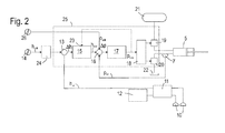
- Fig. 2 shows a block diagram of a control unit 25, which evaluates the signals of the sensors 7, 10 to control the actuators 5.
- the right and left height sensors 10 are connected to a first arithmetic unit 11, which forms an average value from the possibly different measured values of the two sensors 10 and outputs this as the actual cutting height h is to the control unit 25 via a first output.
- the arithmetic unit 11 may also have a second output for a signal derived from the difference between the measured values of the height sensors 10, which is used by a control unit 12, which is not described here in more detail, in order to control the actuators 6 and thus rotate the cutting unit 3 to drive the axis parallel to the direction of travel, which minimizes the difference between the measured values of the height sensors 10.
- the control unit 25 may be a microprocessor in which the subunits of the control unit 25 described below are respectively implemented in the form of subroutines; alternatively, the subunits or at least some of them may be constructed as discrete circuits.
- a difference-forming arithmetic circuit 13 receives the actual cutting height signal h ist from the arithmetic unit 11 and a nominal cutting height signal h soll , which has been set by the driver of the harvester to an input means 14 mounted in the driver's cab.
- a, b are suitably fixed constants. (Other terms other than proportional or integral to ⁇ h may be included in the height correction signal.)
- a difference between the height correction signal h corr and a pressure actual value p ist delivered by the pressure sensors 7 of the actuators 5 is formed and transferred as a pressure deviation signal ⁇ p to a second control loop 17.
- the second control circuit 17, which corr converts the pressure deviation signal Ap in a pressure correction signal p can be designed as a pure or substantially pure proportional control valve to the pressure correction signal p corr is any change of the actual pressure p or the altitude correction signal h corr high speed tracking to can.
- a valve driver circuit 18 is connected to the output of the second control circuit 17 to receive the pressure correction signal p corr . Based on the pressure correction signal p corr , the valve driver circuit 18 controls two proportional valves 19, 20, one of which 19 is disposed between a high pressure reservoir 21 and one of the actuators 5 and the other 20 is disposed between the actuator 5 and a pressureless tank 22 for hydraulic fluid ,
- the pressure sensor 7 is shown here at a line section between the actuator 5 and the proportional valve 20, it could just as well be located on a line section between the proportional valve 19 and the actuator 5 or directly to a chamber of the actuator 5.
- the proportional valves 19, 20 are solenoid valves, the degree of opening of which depends on the current supplied to it by the valve driver circuit 18. As long as this is below a lower limit current intensity which is dependent on the type of valves 19, 20, the valves 19, 20 are closed; If the limit current intensity is exceeded, then the fluid flow rate of the valves 19, 20 increases continuously with the current intensity.
- the driver circuit 18 holds both valves 19, 20 closed, but applied to both but with the limiting current, so that when p corrorr of 0, not only a magnetic field in the then openable valve 19, 20 must be constructed and the inductance of the solenoid valves delays the increase of the injected current but the opening degree of the valve 19 or 20 may follow a change in the injected current with minimal delay.
- the driver circuit 18 opens the valve 19 while the valve 20 remains closed and a resultant flow of hydraulic fluid from the high pressure reservoir 21 causes a rapid increase in pressure in the actuator 5 and if it continues for a longer time
- the drive circuit 18 keeps closed at p corr ⁇ 0, the valve 19 and opens the valve 20 so that the pressure on the actuator 5 decreases rapidly, the actuator 5 retracts and the cutting unit 3 drops.
- the input means 14 which may be, for example, a switch, a slider or the like, allows the driver to quickly switch the target cutting height.
- the target cutting height must be set to 0, ie the cutting unit 3 must touch the ground. If the driver for this purpose on the input means 14 h should switch to 0 while the cutter 3 is held above the ground, the height deviation .DELTA.h jump abruptly to a greatly different from 0, the 17 effect on the proportional component in the output of the first control circuit 15 and the substantially pure proportionally operating second control loop quickly to the pressure correction signal p corr and causes the pressure correction signal p corr is strongly negative. The driver circuit 18 then opens the valve 20 far, and the cutting unit 3 drops rapidly.
- ⁇ h is again 0.
- the cutting unit 3 bounces unbraked on the ground, according to a preferred development between the input means 14 and the arithmetic circuit 13, a low-pass filter 24 is provided , Regardless of how quickly the switching of the desired height takes place at the input means 14, the low-pass filter 24 causes the setpoint applied to the input of the arithmetic circuit 13 to approach slowly the value set by the user.
- ⁇ h can already take on very small values, or even change its sign, before the cutter 3 contacts the ground, with the result that it approaches the ground slowly and hard seating is avoided.
- the arithmetic circuit 16 also has an input for a setpoint pressure signal p soll , which the driver adjusts at a second input means 26.
- the influence of one on the second input means 26 set target pressure p should be low on the function of the control unit 25. Namely, when the height h of the cutting unit 3 below the target value h, is to grow through the integral component, the height correction signal corr h continuously. As a result, p korr also increases until the pressure in the actuator 5 is sufficient to lift the cutting unit 3.
Landscapes
- Life Sciences & Earth Sciences (AREA)
- Environmental Sciences (AREA)
- Harvester Elements (AREA)
- Lifting Devices For Agricultural Implements (AREA)
Applications Claiming Priority (1)
| Application Number | Priority Date | Filing Date | Title |
|---|---|---|---|
| DE102012012907.6A DE102012012907A1 (de) | 2012-06-28 | 2012-06-28 | Selbstfahrende Erntemaschine mithöhengeregeltem Schneidwerk |
Publications (2)
| Publication Number | Publication Date |
|---|---|
| EP2679086A1 true EP2679086A1 (fr) | 2014-01-01 |
| EP2679086B1 EP2679086B1 (fr) | 2016-03-23 |
Family
ID=48040032
Family Applications (1)
| Application Number | Title | Priority Date | Filing Date |
|---|---|---|---|
| EP13161513.0A Active EP2679086B1 (fr) | 2012-06-28 | 2013-03-28 | Machine de récolte automotrice dotée d'un tête de coupe réglable en hauteur |
Country Status (4)
| Country | Link |
|---|---|
| US (1) | US9345191B2 (fr) |
| EP (1) | EP2679086B1 (fr) |
| DE (1) | DE102012012907A1 (fr) |
| RU (1) | RU2630230C2 (fr) |
Cited By (5)
| Publication number | Priority date | Publication date | Assignee | Title |
|---|---|---|---|---|
| CN105340468A (zh) * | 2015-10-22 | 2016-02-24 | 江苏大学 | 一种差速式履带联合收割机试验车电液控制系统及方法 |
| EP3072379A1 (fr) * | 2015-03-26 | 2016-09-28 | Deere & Company | Amortissement du tangage d'un vehicule de travail par modification de la vitesse |
| EP3141103A1 (fr) * | 2015-09-09 | 2017-03-15 | CNH Industrial Belgium nv | Procede et appareil de commande automatique d'une hauteur de coupe sur une moissonneuse agricole |
| EP3569050A1 (fr) * | 2018-05-07 | 2019-11-20 | CNH Industrial Belgium N.V. | Procédé et système permettant de contrôler la hauteur d'un outil agricole par rapport au sol |
| CN116234432A (zh) * | 2020-09-30 | 2023-06-06 | 株式会社久保田 | 收获机 |
Families Citing this family (17)
| Publication number | Priority date | Publication date | Assignee | Title |
|---|---|---|---|---|
| CN102686100B (zh) | 2010-01-13 | 2016-03-30 | 株式会社Ihi | 草坪修剪车辆 |
| JP6433368B2 (ja) * | 2015-04-10 | 2018-12-05 | 株式会社クボタ | 草刈走行車両 |
| US20160316619A1 (en) * | 2015-05-01 | 2016-11-03 | Deere & Company | Height of cut control system |
| US9668412B2 (en) * | 2015-05-01 | 2017-06-06 | Deere & Company | Harvesting head height control circuit |
| US10624263B2 (en) * | 2016-06-21 | 2020-04-21 | Macdon Industries Ltd | Crop machine with an electronically controlled hydraulic cylinder flotation system |
| US9968033B2 (en) * | 2016-06-21 | 2018-05-15 | Macdon Industries Ltd. | Crop machine with an electronically controlled hydraulic cylinder flotation system |
| US10455765B2 (en) * | 2017-08-31 | 2019-10-29 | Cnh Industrial America Llc | Method and system for controlling the height of agricultural implement relative to the ground |
| US11383728B2 (en) | 2019-03-14 | 2022-07-12 | Cnh Industrial America Llc | System and method for collecting data associated with the operation of an agricultural machine in different operating modes |
| CN110199663A (zh) * | 2019-04-09 | 2019-09-06 | 丰疆智能科技股份有限公司 | 自动收割机、割台自动调节系统及其方法 |
| AR118624A1 (es) | 2019-04-10 | 2021-10-20 | Cnh Ind America Llc | Sistema de detección de sobrecarga para un cabezal de cosecha |
| US11375654B2 (en) * | 2019-10-08 | 2022-07-05 | Deere & Company | Method and apparatus for adjusting a harvesting header float system based on machine pitch or terrain and system thereof |
| US11497164B2 (en) * | 2019-10-22 | 2022-11-15 | Cnh Industrial America Llc | Header suspension for pivoting header of combine harvester |
| CN111436276A (zh) * | 2020-04-01 | 2020-07-24 | 新疆牧神机械有限责任公司 | 割台仿形系统及其控制方法 |
| AU2021281222A1 (en) * | 2020-05-29 | 2022-12-15 | Cnh Industrial America Llc | Header height control for combine harvester |
| US20220053693A1 (en) * | 2020-08-24 | 2022-02-24 | Cnh Industrial America Llc | Ground pressure feedback sensor system for controlling header float |
| US11737390B2 (en) | 2021-02-23 | 2023-08-29 | Cnh Industrial America Llc | Harvesting header multi-sensor height control |
| DE102023125574A1 (de) * | 2023-09-21 | 2025-03-27 | Claas Selbstfahrende Erntemaschinen Gmbh | Fehlererkennung eines hydraulischen Linearantriebs |
Citations (3)
| Publication number | Priority date | Publication date | Assignee | Title |
|---|---|---|---|---|
| DE3807610A1 (de) | 1988-03-09 | 1989-09-21 | Claas Ohg | Vorrichtung und verfahren zur lageregelung eines maehwerkes |
| EP0786200A2 (fr) * | 1996-01-27 | 1997-07-30 | Robert Bosch Gmbh | Dispositif de régulation de position d'une unité de travail d'une machine agricole |
| US5704200A (en) * | 1995-11-06 | 1998-01-06 | Control Concepts, Inc. | Agricultural harvester ground tracking control system and method using fuzzy logic |
Family Cites Families (8)
| Publication number | Priority date | Publication date | Assignee | Title |
|---|---|---|---|---|
| US4136508A (en) * | 1977-01-07 | 1979-01-30 | Allis-Chalmers Corporation | Closed-loop combine header height control |
| SU1012826A1 (ru) * | 1981-07-14 | 1983-04-23 | Khabrat Nikolaj | Жатка,навешиваема на наклонную камеру комбайна |
| US4414792A (en) * | 1982-03-30 | 1983-11-15 | Blackwelders | Height control for agricultural machine |
| SU1060134A1 (ru) * | 1982-05-07 | 1983-12-15 | Производственное Объединение "Гомсельмаш" | Устройство дл автоматического регулировани высоты среза к уборочной машине |
| US5455769A (en) * | 1994-06-24 | 1995-10-03 | Case Corporation | Combine head raise and lower rate control |
| RU2157613C1 (ru) * | 1999-03-12 | 2000-10-20 | Открытое акционерное общество "Тульский комбайновый завод" | Кормоуборочный комбайн |
| US6615570B2 (en) * | 2001-06-28 | 2003-09-09 | Deere & Company | Header position control with forward contour prediction |
| US7401455B1 (en) * | 2007-01-03 | 2008-07-22 | Cnh America Llc | System and method for controlling the base cutter height of a sugar cane harvester |
-
2012
- 2012-06-28 DE DE102012012907.6A patent/DE102012012907A1/de not_active Withdrawn
-
2013
- 2013-03-28 EP EP13161513.0A patent/EP2679086B1/fr active Active
- 2013-05-30 US US13/905,443 patent/US9345191B2/en active Active
- 2013-06-14 RU RU2013126961A patent/RU2630230C2/ru active
Patent Citations (3)
| Publication number | Priority date | Publication date | Assignee | Title |
|---|---|---|---|---|
| DE3807610A1 (de) | 1988-03-09 | 1989-09-21 | Claas Ohg | Vorrichtung und verfahren zur lageregelung eines maehwerkes |
| US5704200A (en) * | 1995-11-06 | 1998-01-06 | Control Concepts, Inc. | Agricultural harvester ground tracking control system and method using fuzzy logic |
| EP0786200A2 (fr) * | 1996-01-27 | 1997-07-30 | Robert Bosch Gmbh | Dispositif de régulation de position d'une unité de travail d'une machine agricole |
Cited By (7)
| Publication number | Priority date | Publication date | Assignee | Title |
|---|---|---|---|---|
| EP3072379A1 (fr) * | 2015-03-26 | 2016-09-28 | Deere & Company | Amortissement du tangage d'un vehicule de travail par modification de la vitesse |
| EP3141103A1 (fr) * | 2015-09-09 | 2017-03-15 | CNH Industrial Belgium nv | Procede et appareil de commande automatique d'une hauteur de coupe sur une moissonneuse agricole |
| US9769982B2 (en) | 2015-09-09 | 2017-09-26 | Cnh Industrial America Llc | Method and apparatus for automatically controlling a cut height of an agricultural harvester |
| CN105340468A (zh) * | 2015-10-22 | 2016-02-24 | 江苏大学 | 一种差速式履带联合收割机试验车电液控制系统及方法 |
| CN105340468B (zh) * | 2015-10-22 | 2017-04-05 | 江苏大学 | 一种差速式履带联合收割机试验车电液控制系统及方法 |
| EP3569050A1 (fr) * | 2018-05-07 | 2019-11-20 | CNH Industrial Belgium N.V. | Procédé et système permettant de contrôler la hauteur d'un outil agricole par rapport au sol |
| CN116234432A (zh) * | 2020-09-30 | 2023-06-06 | 株式会社久保田 | 收获机 |
Also Published As
| Publication number | Publication date |
|---|---|
| RU2013126961A (ru) | 2014-12-20 |
| US9345191B2 (en) | 2016-05-24 |
| EP2679086B1 (fr) | 2016-03-23 |
| DE102012012907A1 (de) | 2014-04-17 |
| US20140000230A1 (en) | 2014-01-02 |
| RU2630230C2 (ru) | 2017-09-06 |
Similar Documents
| Publication | Publication Date | Title |
|---|---|---|
| EP2679086B1 (fr) | Machine de récolte automotrice dotée d'un tête de coupe réglable en hauteur | |
| EP3072379B1 (fr) | Amortissement du tangage d'un vehicule de travail par modification de la vitesse | |
| EP2269432B1 (fr) | Véhicule agricole | |
| EP1757182B1 (fr) | Presse agricole | |
| WO2009049962A1 (fr) | Dispositif de levage hydraulique | |
| EP3753407B1 (fr) | Appareil agricole à réglage de l'inclinaison amélioré | |
| DE102020124867B4 (de) | Verbesserte Hydraulikvorrichtung | |
| DE102015003153A1 (de) | Selbstfahrende Baumaschine | |
| DE102017012124A1 (de) | Verfahren zur Steuerung der Höhenlage eines Niederhalters einer Bodenfräsmaschine und Bodenfräsmaschine | |
| DE102014206234B4 (de) | Fahrzeug mit Bodenbearbeitungsgerät und Antriebsschlupfregelung | |
| DE102015104690A1 (de) | Landwirtschaftliche Maschine und Sicherheitsverfahren | |
| EP3210447B1 (fr) | Détermination autonome de paramètres de réglage d'un système de commande d'un actionneur de déplacement d'un élément mobile d'une machine de travail agricole | |
| DE102020212111A1 (de) | Rückkopplungskreisantriebssysteme mit geschlossenem regelkreis für motorgrader | |
| EP3975712B1 (fr) | Système de commande et/ou de régulation destiné à un appareil agricole | |
| EP4190973B1 (fr) | Machine à fraiser le sol, en particulier machine à fraiser ou à recycler, et procédé de fonctionnement d'une machine à fraiser le sol | |
| EP3975711B1 (fr) | Système de commande et/ou de régulation pour une machine agricole | |
| EP0249207B1 (fr) | Dispositif de réglage du niveau pour véhicules à moteur | |
| DE102008032104A1 (de) | Landmaschine | |
| AT17986U1 (de) | Verfahren zum Betreiben eines landwirtschaftlichen Ladewagens und landwirtschaftlicher Ladewagen | |
| DE102015118049A1 (de) | Fahrzeug mit verbesserter Anhängervorrichtung | |
| EP4656030A1 (fr) | Moissonneuse agricole automotrice | |
| DE102024128251A1 (de) | Landwirtschaftliche Verteilmaschine und Verfahren zum Betrieb einer landwirtschaftlichen Verteilmaschine | |
| EP4321021A1 (fr) | Système de commande et/ou de régulation, véhicule utilitaire agricole | |
| DE102021002610A1 (de) | Fahrbare Arbeitsmaschine | |
| DE202022002936U1 (de) | Landwirtschaftliches Gerät mit verbesserter Neigungsregelung |
Legal Events
| Date | Code | Title | Description |
|---|---|---|---|
| PUAI | Public reference made under article 153(3) epc to a published international application that has entered the european phase |
Free format text: ORIGINAL CODE: 0009012 |
|
| AK | Designated contracting states |
Kind code of ref document: A1 Designated state(s): AL AT BE BG CH CY CZ DE DK EE ES FI FR GB GR HR HU IE IS IT LI LT LU LV MC MK MT NL NO PL PT RO RS SE SI SK SM TR |
|
| AX | Request for extension of the european patent |
Extension state: BA ME |
|
| 17P | Request for examination filed |
Effective date: 20140701 |
|
| RBV | Designated contracting states (corrected) |
Designated state(s): AL AT BE BG CH CY CZ DE DK EE ES FI FR GB GR HR HU IE IS IT LI LT LU LV MC MK MT NL NO PL PT RO RS SE SI SK SM TR |
|
| GRAP | Despatch of communication of intention to grant a patent |
Free format text: ORIGINAL CODE: EPIDOSNIGR1 |
|
| INTG | Intention to grant announced |
Effective date: 20151221 |
|
| GRAS | Grant fee paid |
Free format text: ORIGINAL CODE: EPIDOSNIGR3 |
|
| GRAA | (expected) grant |
Free format text: ORIGINAL CODE: 0009210 |
|
| AK | Designated contracting states |
Kind code of ref document: B1 Designated state(s): AL AT BE BG CH CY CZ DE DK EE ES FI FR GB GR HR HU IE IS IT LI LT LU LV MC MK MT NL NO PL PT RO RS SE SI SK SM TR |
|
| REG | Reference to a national code |
Ref country code: GB Ref legal event code: FG4D Free format text: NOT ENGLISH |
|
| REG | Reference to a national code |
Ref country code: FR Ref legal event code: PLFP Year of fee payment: 4 |
|
| REG | Reference to a national code |
Ref country code: CH Ref legal event code: EP |
|
| REG | Reference to a national code |
Ref country code: AT Ref legal event code: REF Ref document number: 782183 Country of ref document: AT Kind code of ref document: T Effective date: 20160415 |
|
| REG | Reference to a national code |
Ref country code: IE Ref legal event code: FG4D Free format text: LANGUAGE OF EP DOCUMENT: GERMAN |
|
| REG | Reference to a national code |
Ref country code: DE Ref legal event code: R096 Ref document number: 502013002243 Country of ref document: DE |
|
| REG | Reference to a national code |
Ref country code: LT Ref legal event code: MG4D |
|
| REG | Reference to a national code |
Ref country code: NL Ref legal event code: MP Effective date: 20160323 |
|
| PG25 | Lapsed in a contracting state [announced via postgrant information from national office to epo] |
Ref country code: GR Free format text: LAPSE BECAUSE OF FAILURE TO SUBMIT A TRANSLATION OF THE DESCRIPTION OR TO PAY THE FEE WITHIN THE PRESCRIBED TIME-LIMIT Effective date: 20160624 Ref country code: HR Free format text: LAPSE BECAUSE OF FAILURE TO SUBMIT A TRANSLATION OF THE DESCRIPTION OR TO PAY THE FEE WITHIN THE PRESCRIBED TIME-LIMIT Effective date: 20160323 Ref country code: NO Free format text: LAPSE BECAUSE OF FAILURE TO SUBMIT A TRANSLATION OF THE DESCRIPTION OR TO PAY THE FEE WITHIN THE PRESCRIBED TIME-LIMIT Effective date: 20160623 Ref country code: FI Free format text: LAPSE BECAUSE OF FAILURE TO SUBMIT A TRANSLATION OF THE DESCRIPTION OR TO PAY THE FEE WITHIN THE PRESCRIBED TIME-LIMIT Effective date: 20160323 |
|
| PG25 | Lapsed in a contracting state [announced via postgrant information from national office to epo] |
Ref country code: NL Free format text: LAPSE BECAUSE OF FAILURE TO SUBMIT A TRANSLATION OF THE DESCRIPTION OR TO PAY THE FEE WITHIN THE PRESCRIBED TIME-LIMIT Effective date: 20160323 Ref country code: LT Free format text: LAPSE BECAUSE OF FAILURE TO SUBMIT A TRANSLATION OF THE DESCRIPTION OR TO PAY THE FEE WITHIN THE PRESCRIBED TIME-LIMIT Effective date: 20160323 Ref country code: SE Free format text: LAPSE BECAUSE OF FAILURE TO SUBMIT A TRANSLATION OF THE DESCRIPTION OR TO PAY THE FEE WITHIN THE PRESCRIBED TIME-LIMIT Effective date: 20160323 Ref country code: RS Free format text: LAPSE BECAUSE OF FAILURE TO SUBMIT A TRANSLATION OF THE DESCRIPTION OR TO PAY THE FEE WITHIN THE PRESCRIBED TIME-LIMIT Effective date: 20160323 Ref country code: LV Free format text: LAPSE BECAUSE OF FAILURE TO SUBMIT A TRANSLATION OF THE DESCRIPTION OR TO PAY THE FEE WITHIN THE PRESCRIBED TIME-LIMIT Effective date: 20160323 |
|
| PG25 | Lapsed in a contracting state [announced via postgrant information from national office to epo] |
Ref country code: IS Free format text: LAPSE BECAUSE OF FAILURE TO SUBMIT A TRANSLATION OF THE DESCRIPTION OR TO PAY THE FEE WITHIN THE PRESCRIBED TIME-LIMIT Effective date: 20160723 Ref country code: PL Free format text: LAPSE BECAUSE OF FAILURE TO SUBMIT A TRANSLATION OF THE DESCRIPTION OR TO PAY THE FEE WITHIN THE PRESCRIBED TIME-LIMIT Effective date: 20160323 Ref country code: EE Free format text: LAPSE BECAUSE OF FAILURE TO SUBMIT A TRANSLATION OF THE DESCRIPTION OR TO PAY THE FEE WITHIN THE PRESCRIBED TIME-LIMIT Effective date: 20160323 |
|
| REG | Reference to a national code |
Ref country code: CH Ref legal event code: PL |
|
| PG25 | Lapsed in a contracting state [announced via postgrant information from national office to epo] |
Ref country code: PT Free format text: LAPSE BECAUSE OF FAILURE TO SUBMIT A TRANSLATION OF THE DESCRIPTION OR TO PAY THE FEE WITHIN THE PRESCRIBED TIME-LIMIT Effective date: 20160725 Ref country code: RO Free format text: LAPSE BECAUSE OF FAILURE TO SUBMIT A TRANSLATION OF THE DESCRIPTION OR TO PAY THE FEE WITHIN THE PRESCRIBED TIME-LIMIT Effective date: 20160323 Ref country code: SM Free format text: LAPSE BECAUSE OF FAILURE TO SUBMIT A TRANSLATION OF THE DESCRIPTION OR TO PAY THE FEE WITHIN THE PRESCRIBED TIME-LIMIT Effective date: 20160323 Ref country code: CZ Free format text: LAPSE BECAUSE OF FAILURE TO SUBMIT A TRANSLATION OF THE DESCRIPTION OR TO PAY THE FEE WITHIN THE PRESCRIBED TIME-LIMIT Effective date: 20160323 Ref country code: ES Free format text: LAPSE BECAUSE OF FAILURE TO SUBMIT A TRANSLATION OF THE DESCRIPTION OR TO PAY THE FEE WITHIN THE PRESCRIBED TIME-LIMIT Effective date: 20160323 Ref country code: SK Free format text: LAPSE BECAUSE OF FAILURE TO SUBMIT A TRANSLATION OF THE DESCRIPTION OR TO PAY THE FEE WITHIN THE PRESCRIBED TIME-LIMIT Effective date: 20160323 |
|
| RAP2 | Party data changed (patent owner data changed or rights of a patent transferred) |
Owner name: CLAAS SELBSTFAHRENDE ERNTEMASCHINEN GMBH |
|
| REG | Reference to a national code |
Ref country code: IE Ref legal event code: MM4A |
|
| PG25 | Lapsed in a contracting state [announced via postgrant information from national office to epo] |
Ref country code: IT Free format text: LAPSE BECAUSE OF FAILURE TO SUBMIT A TRANSLATION OF THE DESCRIPTION OR TO PAY THE FEE WITHIN THE PRESCRIBED TIME-LIMIT Effective date: 20160323 |
|
| REG | Reference to a national code |
Ref country code: DE Ref legal event code: R097 Ref document number: 502013002243 Country of ref document: DE |
|
| PLBE | No opposition filed within time limit |
Free format text: ORIGINAL CODE: 0009261 |
|
| STAA | Information on the status of an ep patent application or granted ep patent |
Free format text: STATUS: NO OPPOSITION FILED WITHIN TIME LIMIT |
|
| PG25 | Lapsed in a contracting state [announced via postgrant information from national office to epo] |
Ref country code: DK Free format text: LAPSE BECAUSE OF FAILURE TO SUBMIT A TRANSLATION OF THE DESCRIPTION OR TO PAY THE FEE WITHIN THE PRESCRIBED TIME-LIMIT Effective date: 20160323 Ref country code: IE Free format text: LAPSE BECAUSE OF NON-PAYMENT OF DUE FEES Effective date: 20160328 Ref country code: CH Free format text: LAPSE BECAUSE OF NON-PAYMENT OF DUE FEES Effective date: 20160331 Ref country code: LI Free format text: LAPSE BECAUSE OF NON-PAYMENT OF DUE FEES Effective date: 20160331 |
|
| PG25 | Lapsed in a contracting state [announced via postgrant information from national office to epo] |
Ref country code: BG Free format text: LAPSE BECAUSE OF FAILURE TO SUBMIT A TRANSLATION OF THE DESCRIPTION OR TO PAY THE FEE WITHIN THE PRESCRIBED TIME-LIMIT Effective date: 20160623 |
|
| 26N | No opposition filed |
Effective date: 20170102 |
|
| REG | Reference to a national code |
Ref country code: FR Ref legal event code: PLFP Year of fee payment: 5 |
|
| PG25 | Lapsed in a contracting state [announced via postgrant information from national office to epo] |
Ref country code: SI Free format text: LAPSE BECAUSE OF FAILURE TO SUBMIT A TRANSLATION OF THE DESCRIPTION OR TO PAY THE FEE WITHIN THE PRESCRIBED TIME-LIMIT Effective date: 20160323 |
|
| PG25 | Lapsed in a contracting state [announced via postgrant information from national office to epo] |
Ref country code: MT Free format text: LAPSE BECAUSE OF FAILURE TO SUBMIT A TRANSLATION OF THE DESCRIPTION OR TO PAY THE FEE WITHIN THE PRESCRIBED TIME-LIMIT Effective date: 20160323 |
|
| GBPC | Gb: european patent ceased through non-payment of renewal fee |
Effective date: 20170328 |
|
| PG25 | Lapsed in a contracting state [announced via postgrant information from national office to epo] |
Ref country code: GB Free format text: LAPSE BECAUSE OF NON-PAYMENT OF DUE FEES Effective date: 20170328 |
|
| REG | Reference to a national code |
Ref country code: FR Ref legal event code: PLFP Year of fee payment: 6 |
|
| PG25 | Lapsed in a contracting state [announced via postgrant information from national office to epo] |
Ref country code: CY Free format text: LAPSE BECAUSE OF FAILURE TO SUBMIT A TRANSLATION OF THE DESCRIPTION OR TO PAY THE FEE WITHIN THE PRESCRIBED TIME-LIMIT Effective date: 20160323 Ref country code: HU Free format text: LAPSE BECAUSE OF FAILURE TO SUBMIT A TRANSLATION OF THE DESCRIPTION OR TO PAY THE FEE WITHIN THE PRESCRIBED TIME-LIMIT; INVALID AB INITIO Effective date: 20130328 |
|
| PG25 | Lapsed in a contracting state [announced via postgrant information from national office to epo] |
Ref country code: MK Free format text: LAPSE BECAUSE OF FAILURE TO SUBMIT A TRANSLATION OF THE DESCRIPTION OR TO PAY THE FEE WITHIN THE PRESCRIBED TIME-LIMIT Effective date: 20160323 Ref country code: MC Free format text: LAPSE BECAUSE OF FAILURE TO SUBMIT A TRANSLATION OF THE DESCRIPTION OR TO PAY THE FEE WITHIN THE PRESCRIBED TIME-LIMIT Effective date: 20160323 Ref country code: LU Free format text: LAPSE BECAUSE OF NON-PAYMENT OF DUE FEES Effective date: 20160328 Ref country code: TR Free format text: LAPSE BECAUSE OF FAILURE TO SUBMIT A TRANSLATION OF THE DESCRIPTION OR TO PAY THE FEE WITHIN THE PRESCRIBED TIME-LIMIT Effective date: 20160323 |
|
| PG25 | Lapsed in a contracting state [announced via postgrant information from national office to epo] |
Ref country code: AL Free format text: LAPSE BECAUSE OF FAILURE TO SUBMIT A TRANSLATION OF THE DESCRIPTION OR TO PAY THE FEE WITHIN THE PRESCRIBED TIME-LIMIT Effective date: 20160323 |
|
| REG | Reference to a national code |
Ref country code: AT Ref legal event code: MM01 Ref document number: 782183 Country of ref document: AT Kind code of ref document: T Effective date: 20180328 |
|
| PG25 | Lapsed in a contracting state [announced via postgrant information from national office to epo] |
Ref country code: AT Free format text: LAPSE BECAUSE OF NON-PAYMENT OF DUE FEES Effective date: 20180328 |
|
| P01 | Opt-out of the competence of the unified patent court (upc) registered |
Effective date: 20230515 |
|
| PGFP | Annual fee paid to national office [announced via postgrant information from national office to epo] |
Ref country code: DE Payment date: 20260319 Year of fee payment: 14 |
|
| PGFP | Annual fee paid to national office [announced via postgrant information from national office to epo] |
Ref country code: BE Payment date: 20260319 Year of fee payment: 14 |
|
| PGFP | Annual fee paid to national office [announced via postgrant information from national office to epo] |
Ref country code: FR Payment date: 20260320 Year of fee payment: 14 |