EP2679313A2 - Verfahren und Vorrichtung zum Auftragen von Leim auf einem elastischen Faden in einem Einweghygieneprodukt - Google Patents
Verfahren und Vorrichtung zum Auftragen von Leim auf einem elastischen Faden in einem Einweghygieneprodukt Download PDFInfo
- Publication number
- EP2679313A2 EP2679313A2 EP13163420.6A EP13163420A EP2679313A2 EP 2679313 A2 EP2679313 A2 EP 2679313A2 EP 13163420 A EP13163420 A EP 13163420A EP 2679313 A2 EP2679313 A2 EP 2679313A2
- Authority
- EP
- European Patent Office
- Prior art keywords
- adhesive
- elastic strand
- dispensing
- volume
- elastic
- Prior art date
- Legal status (The legal status is an assumption and is not a legal conclusion. Google has not performed a legal analysis and makes no representation as to the accuracy of the status listed.)
- Granted
Links
- 239000000853 adhesive Substances 0.000 title claims abstract description 570
- 230000001070 adhesive effect Effects 0.000 title claims abstract description 570
- 238000000034 method Methods 0.000 title claims abstract description 53
- 239000000758 substrate Substances 0.000 claims abstract description 71
- 238000005086 pumping Methods 0.000 claims description 17
- 230000009467 reduction Effects 0.000 abstract description 3
- 239000011248 coating agent Substances 0.000 description 19
- 238000000576 coating method Methods 0.000 description 19
- 230000009977 dual effect Effects 0.000 description 13
- 239000000463 material Substances 0.000 description 11
- 239000004831 Hot glue Substances 0.000 description 8
- 238000004519 manufacturing process Methods 0.000 description 4
- 238000007664 blowing Methods 0.000 description 3
- 238000010276 construction Methods 0.000 description 2
- 239000007788 liquid Substances 0.000 description 2
- 238000012986 modification Methods 0.000 description 2
- 230000004048 modification Effects 0.000 description 2
- 206010021639 Incontinence Diseases 0.000 description 1
- 239000011324 bead Substances 0.000 description 1
- 238000007796 conventional method Methods 0.000 description 1
- 230000001351 cycling effect Effects 0.000 description 1
- 239000013013 elastic material Substances 0.000 description 1
- 230000007246 mechanism Effects 0.000 description 1
- 239000000155 melt Substances 0.000 description 1
- 230000008569 process Effects 0.000 description 1
- 238000009877 rendering Methods 0.000 description 1
- 238000000926 separation method Methods 0.000 description 1
- 238000011144 upstream manufacturing Methods 0.000 description 1
- 239000002699 waste material Substances 0.000 description 1
Images


Classifications
-
- B—PERFORMING OPERATIONS; TRANSPORTING
- B05—SPRAYING OR ATOMISING IN GENERAL; APPLYING FLUENT MATERIALS TO SURFACES, IN GENERAL
- B05B—SPRAYING APPARATUS; ATOMISING APPARATUS; NOZZLES
- B05B9/00—Spraying apparatus for discharge of liquids or other fluent material, without essentially mixing with gas or vapour
- B05B9/03—Spraying apparatus for discharge of liquids or other fluent material, without essentially mixing with gas or vapour characterised by means for supplying liquid or other fluent material
- B05B9/04—Spraying apparatus for discharge of liquids or other fluent material, without essentially mixing with gas or vapour characterised by means for supplying liquid or other fluent material with pressurised or compressible container; with pump
- B05B9/0403—Spraying apparatus for discharge of liquids or other fluent material, without essentially mixing with gas or vapour characterised by means for supplying liquid or other fluent material with pressurised or compressible container; with pump with pumps for liquids or other fluent material
-
- A—HUMAN NECESSITIES
- A61—MEDICAL OR VETERINARY SCIENCE; HYGIENE
- A61F—FILTERS IMPLANTABLE INTO BLOOD VESSELS; PROSTHESES; DEVICES PROVIDING PATENCY TO, OR PREVENTING COLLAPSING OF, TUBULAR STRUCTURES OF THE BODY, e.g. STENTS; ORTHOPAEDIC, NURSING OR CONTRACEPTIVE DEVICES; FOMENTATION; TREATMENT OR PROTECTION OF EYES OR EARS; BANDAGES, DRESSINGS OR ABSORBENT PADS; FIRST-AID KITS
- A61F13/00—Bandages or dressings; Absorbent pads
- A61F13/15—Absorbent pads, e.g. sanitary towels, swabs or tampons for external or internal application to the body; Supporting or fastening means therefor; Tampon applicators
- A61F13/15577—Apparatus or processes for manufacturing
- A61F13/15585—Apparatus or processes for manufacturing of babies' napkins, e.g. diapers
- A61F13/15593—Apparatus or processes for manufacturing of babies' napkins, e.g. diapers having elastic ribbons fixed thereto; Devices for applying the ribbons
-
- A—HUMAN NECESSITIES
- A61—MEDICAL OR VETERINARY SCIENCE; HYGIENE
- A61F—FILTERS IMPLANTABLE INTO BLOOD VESSELS; PROSTHESES; DEVICES PROVIDING PATENCY TO, OR PREVENTING COLLAPSING OF, TUBULAR STRUCTURES OF THE BODY, e.g. STENTS; ORTHOPAEDIC, NURSING OR CONTRACEPTIVE DEVICES; FOMENTATION; TREATMENT OR PROTECTION OF EYES OR EARS; BANDAGES, DRESSINGS OR ABSORBENT PADS; FIRST-AID KITS
- A61F13/00—Bandages or dressings; Absorbent pads
- A61F13/15—Absorbent pads, e.g. sanitary towels, swabs or tampons for external or internal application to the body; Supporting or fastening means therefor; Tampon applicators
- A61F13/15577—Apparatus or processes for manufacturing
-
- A—HUMAN NECESSITIES
- A61—MEDICAL OR VETERINARY SCIENCE; HYGIENE
- A61F—FILTERS IMPLANTABLE INTO BLOOD VESSELS; PROSTHESES; DEVICES PROVIDING PATENCY TO, OR PREVENTING COLLAPSING OF, TUBULAR STRUCTURES OF THE BODY, e.g. STENTS; ORTHOPAEDIC, NURSING OR CONTRACEPTIVE DEVICES; FOMENTATION; TREATMENT OR PROTECTION OF EYES OR EARS; BANDAGES, DRESSINGS OR ABSORBENT PADS; FIRST-AID KITS
- A61F13/00—Bandages or dressings; Absorbent pads
- A61F13/15—Absorbent pads, e.g. sanitary towels, swabs or tampons for external or internal application to the body; Supporting or fastening means therefor; Tampon applicators
- A61F13/45—Absorbent pads, e.g. sanitary towels, swabs or tampons for external or internal application to the body; Supporting or fastening means therefor; Tampon applicators characterised by the shape
- A61F13/49—Absorbent pads, e.g. sanitary towels, swabs or tampons for external or internal application to the body; Supporting or fastening means therefor; Tampon applicators characterised by the shape specially adapted to be worn around the waist, e.g. diapers, nappies
- A61F13/49007—Form-fitting, self-adjusting disposable diapers
- A61F13/49009—Form-fitting, self-adjusting disposable diapers with elastic means
- A61F13/49017—Form-fitting, self-adjusting disposable diapers with elastic means the elastic means being located at the crotch region
-
- B—PERFORMING OPERATIONS; TRANSPORTING
- B05—SPRAYING OR ATOMISING IN GENERAL; APPLYING FLUENT MATERIALS TO SURFACES, IN GENERAL
- B05B—SPRAYING APPARATUS; ATOMISING APPARATUS; NOZZLES
- B05B12/00—Arrangements for controlling delivery; Arrangements for controlling the spray area
-
- B—PERFORMING OPERATIONS; TRANSPORTING
- B05—SPRAYING OR ATOMISING IN GENERAL; APPLYING FLUENT MATERIALS TO SURFACES, IN GENERAL
- B05B—SPRAYING APPARATUS; ATOMISING APPARATUS; NOZZLES
- B05B12/00—Arrangements for controlling delivery; Arrangements for controlling the spray area
- B05B12/02—Arrangements for controlling delivery; Arrangements for controlling the spray area for controlling time, or sequence, of delivery
- B05B12/04—Arrangements for controlling delivery; Arrangements for controlling the spray area for controlling time, or sequence, of delivery for sequential operation or multiple outlets
-
- B—PERFORMING OPERATIONS; TRANSPORTING
- B05—SPRAYING OR ATOMISING IN GENERAL; APPLYING FLUENT MATERIALS TO SURFACES, IN GENERAL
- B05B—SPRAYING APPARATUS; ATOMISING APPARATUS; NOZZLES
- B05B12/00—Arrangements for controlling delivery; Arrangements for controlling the spray area
- B05B12/08—Arrangements for controlling delivery; Arrangements for controlling the spray area responsive to condition of liquid or other fluent material to be discharged, of ambient medium or of target ; responsive to condition of spray devices or of supply means, e.g. pipes, pumps or their drive means
- B05B12/085—Arrangements for controlling delivery; Arrangements for controlling the spray area responsive to condition of liquid or other fluent material to be discharged, of ambient medium or of target ; responsive to condition of spray devices or of supply means, e.g. pipes, pumps or their drive means responsive to flow or pressure of liquid or other fluent material to be discharged
-
- B—PERFORMING OPERATIONS; TRANSPORTING
- B05—SPRAYING OR ATOMISING IN GENERAL; APPLYING FLUENT MATERIALS TO SURFACES, IN GENERAL
- B05C—APPARATUS FOR APPLYING FLUENT MATERIALS TO SURFACES, IN GENERAL
- B05C5/00—Apparatus in which liquid or other fluent material is projected, poured or allowed to flow on to the surface of the work
- B05C5/02—Apparatus in which liquid or other fluent material is projected, poured or allowed to flow on to the surface of the work the liquid or other fluent material being discharged through an outlet orifice by pressure, e.g. from an outlet device in contact or almost in contact, with the work
- B05C5/0241—Apparatus in which liquid or other fluent material is projected, poured or allowed to flow on to the surface of the work the liquid or other fluent material being discharged through an outlet orifice by pressure, e.g. from an outlet device in contact or almost in contact, with the work for applying liquid or other fluent material to elongated work, e.g. wires, cables, tubes
-
- B—PERFORMING OPERATIONS; TRANSPORTING
- B05—SPRAYING OR ATOMISING IN GENERAL; APPLYING FLUENT MATERIALS TO SURFACES, IN GENERAL
- B05C—APPARATUS FOR APPLYING FLUENT MATERIALS TO SURFACES, IN GENERAL
- B05C9/00—Apparatus or plant for applying liquid or other fluent material to surfaces by means not covered by any preceding group, or in which the means of applying the liquid or other fluent material is not important
- B05C9/06—Apparatus or plant for applying liquid or other fluent material to surfaces by means not covered by any preceding group, or in which the means of applying the liquid or other fluent material is not important for applying two different liquids or other fluent materials, or the same liquid or other fluent material twice, to the same side of the work
-
- B—PERFORMING OPERATIONS; TRANSPORTING
- B05—SPRAYING OR ATOMISING IN GENERAL; APPLYING FLUENT MATERIALS TO SURFACES, IN GENERAL
- B05D—PROCESSES FOR APPLYING FLUENT MATERIALS TO SURFACES, IN GENERAL
- B05D1/00—Processes for applying liquids or other fluent materials
- B05D1/40—Distributing applied liquids or other fluent materials by members moving relatively to surface
- B05D1/42—Distributing applied liquids or other fluent materials by members moving relatively to surface by non-rotary members
-
- B—PERFORMING OPERATIONS; TRANSPORTING
- B32—LAYERED PRODUCTS
- B32B—LAYERED PRODUCTS, i.e. PRODUCTS BUILT-UP OF STRATA OF FLAT OR NON-FLAT, e.g. CELLULAR OR HONEYCOMB, FORM
- B32B37/00—Methods or apparatus for laminating, e.g. by curing or by ultrasonic bonding
- B32B37/12—Methods or apparatus for laminating, e.g. by curing or by ultrasonic bonding characterised by using adhesives
- B32B37/1284—Application of adhesive
- B32B37/1292—Application of adhesive selectively, e.g. in stripes, in patterns
Definitions
- the present invention generally relates to a method and apparatus for dispensing adhesive and more particularly, to a method and apparatus for dispensing adhesive onto at least one elastic strand during construction of a personal disposable hygiene product.
- Liquid adhesive such as hot melt adhesive
- a hot melt adhesive filament to one or more stretched elastic strands, which are then adhered to a nonwoven substrate to form an elasticized portion of the disposable personal hygiene product.
- the various components e.g., flat substrate layers and elastic strands
- One well understood method of improving the quality of an adhesive bond and thereby reducing creep is by applying additional adhesive on the substrate or the elastic strand(s).
- applying too much adhesive to the elastic strand locks the elastic strand along its length and thereby reduces the effectiveness of the elastic material to apply force to the substrate.
- the elastic strand loses the ability to apply sufficient retraction force to the substrate.
- increasing the amount of adhesive used in disposable personal hygiene product manufacturing significantly increases cost and also reduces the "hand" or softness of the resulting product. Applying too much adhesive material may also lead to "burn through,” which occurs when the adhesive material burns or melts through the adhered substrate. Consequently, the amount of adhesive used to adhere elastic strands to substrates should be minimized while also maintaining a high level of creep resistance, a high retraction force, and minimized burn through and stiffness.
- a method of dispensing adhesive onto at least one stretched elastic strand to be adhered to a substrate to form a personal disposable hygiene product includes moving the stretched elastic strand along a machine direction and applying a first volume of adhesive onto a first portion of the elastic strand.
- the method also includes applying a second volume of adhesive onto a second portion of the elastic strand located downstream from the first portion relative to the machine direction, and applying a third volume of adhesive onto a third portion of the elastic strand located downstream from the second portion relative to the machine direction.
- the second volume is less than the first volume and less than the third volume.
- the first and third portions of the elastic strand collectively define a first length and the second portion of the elastic strand defines a second length longer than the first length.
- the second volume of adhesive is applied over a majority of the elastic strand.
- applying the first, second, and third volumes of adhesive includes dispensing a first quantity of adhesive onto the first and third portions of the elastic strand, and dispensing a second quantity of adhesive onto the first, second, and third portions of the elastic strand.
- the second quantity defines the second volume of adhesive on the second portion of the elastic strand.
- the first and second quantities collectively define the first volume of adhesive on the first portion of the elastic strand and the third volume of adhesive on the third portion of the elastic strand.
- applying the first, second, and third volumes of adhesive includes dispensing a first quantity of adhesive onto the first and third portions of the elastic strand and dispensing a second quantity of adhesive onto the second portion of the elastic strand.
- the first quantity of adhesive defines the first volume of adhesive on the first portion of the elastic strand and the third volume of adhesive on the third portion of the elastic strand, while the second quantity of adhesive defines the second volume on the second portion of the elastic strand.
- the first and second quantities of adhesive may be dispensed simultaneously onto the first portion and then onto the third portion of the elastic strand, or one of the first and second quantities may be dispensed onto the elastic strand before the other quantity.
- the first and second quantities are dispensed by respective first and second dispensing nozzles, which are fed adhesive at first and second predetermined or adjustable flow rates.
- first, second, and third volumes of adhesive are dispensed by a single dispensing nozzle including first and second valves that control flow from corresponding first and second adhesive supplies.
- first and second valves are opened to apply the first volume of adhesive to the first portion of the elastic strand.
- Closing the second valve while leaving the first valve open causes the second volume of adhesive to be applied to the second portion of the elastic strand.
- Opening the first and second valves causes the third volume of adhesive to be applied to the third portion of the elastic strand.
- adhesive is pumped at an adjustable first flow rate to the first valve and adhesive is pumped at an adjustable second flow rate to the second valve.
- a method of dispensing adhesive onto a plurality of stretched elastic strands to be adhered to a substrate to form a personal disposable hygiene product includes moving each of the stretched elastic strands along a machine direction. The method further includes applying a first volume of adhesive onto a first portion of each of the elastic strands, applying a second volume of adhesive onto a second portion of each of the elastic strands located downstream from the first portion, and applying a third volume of adhesive onto a third portion of each of the elastic strands located downstream from the second portion. The second volume is less than the first volume and less than the third volume.
- Applying the first, second, and third volumes of adhesive may include dispensing at least one quantity of adhesive individually onto each of the plurality of elastic strands, or dispensing at least one quantity of adhesive collectively onto all of the plurality of elastic strands.
- a personal disposable hygiene product in another embodiment, includes a nonwoven substrate with first and second longitudinal sides.
- the hygiene product also includes first and second stretched elastic strands adhered to the nonwoven substrate respectively along the first and second longitudinal sides.
- Each of the elastic strands includes a first portion defining an end of the elastic strand, a second portion defining a central portion of the elastic strand, and a third portion defining another end of the elastic strand.
- the first portions are coated with a first volume of adhesive
- the second portions are coated with a second volume of adhesive
- the third portions are coated with a third volume of adhesive.
- the second volume of adhesive is less than each of the first and third volumes of adhesive.
- a dispensing apparatus applies adhesive to at least one stretched elastic strand including first, second, and third portions along a length of the elastic strand that are to be adhered to a substrate to form a personal disposable hygiene product.
- the apparatus includes a first dispensing nozzle for dispensing a first volume of adhesive onto the stretched elastic strand at the first portion and for dispensing a third volume of adhesive onto the stretched elastic strand at the third portion.
- the apparatus also includes a second dispensing nozzle for dispensing a second volume of adhesive onto the stretched elastic strand at a second portion extending between the first and third portions.
- the second volume of adhesive is less than each of the first and third volumes of adhesive.
- the first dispensing nozzle includes a strand guide, while the second dispensing nozzle does not include a strand guide.
- the dispensing nozzles may include the same type of dispensing nozzle or different types of dispensing nozzles.
- the dispensing apparatus also includes a first adhesive supply for pumping adhesive to the first dispensing nozzle, a second adhesive supply for pumping adhesive to the second dispensing nozzle, and a control for selectively actuating the first and second adhesive supplies.
- a dispensing apparatus applies adhesive to at least one stretched elastic strand including first, second, and third portions along a length of the elastic strand that are to be adhered to a substrate to form a personal disposable hygiene product.
- the apparatus includes a first dispensing nozzle for dispensing a first quantity of adhesive onto the stretched elastic strand at the first and third portions.
- the apparatus also includes a second dispensing nozzle for dispensing a second quantity of adhesive onto the stretched elastic strand at the first, second, and third portions.
- the first and second quantities of adhesive collectively define a first volume of adhesive on the first portion of the elastic strand and a third volume of adhesive on the third portion of the elastic strand.
- the second quantity of adhesive defines a second volume of adhesive on the second portion of the elastic strand that is less than each of the first and third volumes of adhesive.
- a dispensing apparatus applies adhesive to at least one stretched elastic strand that is to be adhered to a substrate to form a personal disposable hygiene product.
- the apparatus includes a single dispensing nozzle for dispensing adhesive onto the stretched elastic strand at first, second, and third portions located in sequence along the length of the elastic strand.
- the dispensing apparatus also includes a first valve adapted to control flow from a first adhesive supply through the dispensing nozzle and a second valve adapted to control flow from a second adhesive supply through the dispensing nozzle.
- the first and second valves are opened to apply a first volume of adhesive on the first portion or to apply a third volume of adhesive on the third portion.
- the first valve is opened while the second valve is closed to apply a second volume of adhesive on the second portion that is less than the first or third volumes of adhesive.
- FIG. 1 is a partially exploded perspective view of a personal disposable hygiene product according to one embodiment of the current invention.
- FIG. 2 is a schematic side view of a dispensing apparatus for applying adhesive to a plurality of stretched elastic strands according to one embodiment of the current invention.
- FIG. 3 is a schematic top view of the dispensing apparatus of FIG. 2 .
- FIG. 4 is a schematic top view of another embodiment of a dispensing apparatus for applying adhesive to elastic strands.
- FIG. 5 is a schematic side view of another embodiment of a dispensing apparatus for applying adhesive to elastic strands.
- FIG. 6 is a schematic top view of the dispensing apparatus of FIG. 5 .
- FIG. 7 is a schematic top view of yet another embodiment of a dispensing apparatus for applying adhesive to elastic strands.
- FIG. 8 is a schematic top view of another embodiment of a dispensing apparatus for applying adhesive to elastic strands.
- FIG. 9 is a schematic top view of yet another embodiment of a dispensing apparatus for applying adhesive to elastic strands.
- FIG. 10 is a schematic top view of yet another embodiment of a dispensing apparatus for applying adhesive to elastic strands.
- FIG. 11 is a schematic top view of another embodiment of a dispensing apparatus for applying adhesive to elastic strands, the dispensing apparatus including two nozzles in parallel.
- FIG. 12A is a schematic front view of the dispensing apparatus of FIG. 11 during a dispensing operation.
- FIG. 12B is a schematic side view of another embodiment of a dispensing apparatus similar to the dispensing apparatus of FIGS. 11 and 12A .
- FIG. 13 is a schematic top view of yet another embodiment of a dispensing apparatus for applying adhesive to elastic strands.
- FIG. 14 is a schematic front view of the dispensing apparatus of FIG. 13 , showing a first set of valves in phantom.
- FIG. 15 is a schematic front view of the dispensing apparatus of FIG. 13 , showing a second set of valves in phantom.
- FIG. 16 is a schematic top view of another embodiment of a dispensing apparatus for applying adhesive to elastic strands.
- FIG. 17 is a schematic top view of yet another embodiment of a dispensing apparatus for applying adhesive to elastic strands.
- FIG. 1 illustrates one embodiment of a disposable personal hygiene product 10 manufactured using an exemplary method and apparatus of the invention.
- the disposable personal hygiene product 10 is a disposable diaper 10 including first and second ends 12, 14 configured to wrap around the waist of the user and a central portion 16 configured to extend between the legs of the user.
- the diaper 10 includes a flat nonwoven substrate 18, leg gathers 20 formed along each longitudinal side 22, 24 of the diaper 10 between the first and second ends 12, 14, and a second flat substrate 26 secured to the nonwoven substrate 18 to enclose the leg gathers 20.
- the second flat substrate 26 is another nonwoven substrate in the illustrated embodiment.
- the leg gathers 20 are formed by one or more elastic strands 28 that are secured to the nonwoven substrate 18 in a stretched condition so as to provide the diaper 10 with elasticity around the legs of the user.
- the nonwoven substrate 18, leg gathers 20, and second substrate 26 are secured to each other with hot melt adhesive 30.
- each of the elastic strands 28 is advantageously adhered to the nonwoven substrate 18 by a varying amount of hot melt adhesive 30 applied along the length of the elastic strand 28.
- this varying amount of adhesive 30 may be applied by first and second dispensing nozzles in series, wherein the first dispensing nozzle may include a strand guide in some embodiments while the second dispensing nozzle cannot include a strand guide.
- each elastic strand 28 includes a first portion 32 adjacent the first end 12, a second portion 34 extending from the first portion 32 and adjacent the central portion 16, and a third portion 36 located adjacent to the second portion 34 and the second end 14.
- the first and third portions 32, 36 define opposing ends of the elastic strand 28 when adhered to the nonwoven substrate 18, while the second portion 34 defines a central portion of the elastic strand 28 during adherence.
- the first portion 32 is coated with a first volume of adhesive 30a
- the second portion 34 is coated with a second volume of adhesive 30b
- the third portion 36 is coated with a third volume of adhesive 30c.
- the second volume of adhesive 30b is less than each of the first and third volumes of adhesive 30a, 30c.
- the elastic strands 28 also include small free ends 38 beyond the first and second end portions 32, 34 that are not coated with adhesive 30 and thus retract or curl up when the remainder of the elastic strands 28 is adhered to the substrate 18.
- volume is used as shorthand to describe an average volume of adhesive per unit length over the corresponding strand portion.
- the average volume of adhesive per unit length applied to the first and third portions 32, 36 of the elastic strand 28 is higher than the average volume of adhesive per unit length applied to the second portion 34.
- the higher first and second volumes of adhesive 30a, 30c along the first and third portions 32, 36 are schematically shown as a thicker spiral filament while a thinner spiral filament is shown at the second portion 34 to indicate the lessened second volume of adhesive 30b.
- the actual pattern applied to the elastic strands 28 may vary in other embodiments, such as by being applied as a plurality of discrete masses of adhesive that produce discrete bond points when adhering the elastic strands 28 to the nonwoven substrate 18.
- volume per unit length is described as roughly constant over the entire length of a corresponding strand portion 32, 34, 36 in the exemplary embodiments below, the volume per unit length may vary over the length of one or more of the strand portions 32, 34, 36 without departing from the scope of the invention (i.e., as long as the "volume” or average volume per unit length remains lesser for the second portion 34 than the first and third portions 32, 36).
- adhesive application patterns shown in FIG. 1 and the following figures on the elastic strands 28 are schematic artist's renderings of these patterns, as it will be understood that these patterns may vary in appearance significantly in a practical setting.
- the first portion 32 of the elastic strand 28 defines a first length L1
- the second portion 34 defines a second length L2
- the third portion 36 defines a third length L3.
- the second length L2 is larger than the first and third lengths L1, L3 combined so that the second volume of adhesive 30b is applied over a majority of the total length of the elastic strand 28.
- the first and third volumes of adhesive 30a, 30c are only applied onto the first and third portions 32, 36 of the elastic strand 28 where such a level of creep resistance is necessary.
- This higher average volume of adhesive per unit length is not used in the second portion 34 of the elastic strand 28 where creep resistance is less of a concern.
- this second portion 34 includes a majority of the elastic strand 28, the total amount of adhesive 30 used to adhere the elastic strand 28 to the substrate 18 is significantly reduced compared to a constant coating over the entire length of the elastic strand 28.
- the diaper 10 of this embodiment advantageously minimizes the amount of adhesive add on necessary to produce a high quality bond or construction of the various components of the diaper 10.
- the dispensing apparatus 40 includes a first dispensing nozzle 42 and a second dispensing nozzle 44 arranged in series along a machine direction indicated by arrow 46.
- the plurality of elastic strands 28 moves along the machine direction 46 past the first dispensing nozzle 42 and then past the second dispensing nozzle 44.
- the first and second dispensing nozzles 42, 44 operate to dispense hot melt adhesive 30 onto the elastic strands 28 so as to coat the elastic strands 28 with the first, second, and third volumes of adhesive 30a, 30b, 30c as described above.
- the elastic strands 28 run continuously through the dispensing apparatus 40 and are cut into separate elastic strands 28 downstream from the dispensing apparatus 40. To enable this cutting separation, the adjacent free ends 38 of two elastic strands 28 in series are not coated with any adhesive material. Consequently, each of the first and second dispensing nozzles 42, 44 cycles on and off repeatedly during operation of the dispensing apparatus 40.
- the first dispensing nozzle 42 is incorporated into a first dispensing module 48 and the second dispensing nozzle 44 is incorporated into a second dispensing module 50 separate from the first dispensing module 48.
- the first dispensing module 48 includes a contact nozzle and the second dispensing module includes a non-contact nozzle, each nozzle being configured to apply a filament, bead, coating, or other amount of adhesive (hereinafter referred to as a "quantity") to the elastic strands 28.
- the first dispensing nozzle 42 shown is a contact nozzle as described in U.S. Patent Application No.
- the second dispensing nozzle 44 shown is a non-contact swirl nozzle such as the UniversalTM CF nozzle commercially available from Nordson Corporation of Westlake, Ohio, which is described in U.S. Patent No. 4,785,996 to Ziecker et al. , the entire disclosure of which is hereby incorporated by reference herein.
- first and second dispensing nozzles 42, 44 are illustrated as different types of nozzles in this embodiment, it will be appreciated that the first dispensing nozzle 42 may be the same type of nozzle as the second dispensing nozzle 44 in other embodiments of the invention, assuming both dispensing nozzles 42, 44 are non-contact nozzles.
- the first dispensing module 48 receives hot melt adhesive 30 from a first adhesive supply 52 and the second dispensing module 50 receives hot melt adhesive 30 from a second adhesive supply 54.
- the first and second adhesive supplies 52, 54 operate to pump heated liquid adhesive 30 to the first and second dispensing nozzles 42, 44.
- the first adhesive supply 52 includes a first individually adjustable pump 52 for supplying an adjustable flow of adhesive 30 to the first dispensing nozzle 42.
- the second adhesive supply 54 includes a second individually adjustable pump 54 separate from the first pump 52 for supplying another adjustable flow of adhesive 30 to the second dispensing nozzle 44.
- the first and second adhesive supplies 52, 54 may be first and second output streams of a common dual stream pump.
- each adhesive supply 52, 54 delivers a predetermined flow of adhesive to each of the first and second dispensing nozzles 42, 44. Therefore, although the first and second adhesive supplies 52, 54 are illustrated as separate elements in FIGS. 2 and 3 , it will be understood that the first and second adhesive supplies 52, 54 may be generated from a single dual stream pump or separate pumps without departing from the scope of the invention. Additionally, it will be understood that this and each of the following embodiments of the dispensing apparatus 40 may also include a control 55 for selectively actuating (e.g., turning on and off) the first and second adhesive supplies 52, 54.
- a control 55 for selectively actuating (e.g., turning on and off) the first and second adhesive supplies 52, 54.
- the operation of the dispensing apparatus 40 is shown schematically in FIGS. 2 and 3 .
- the plurality of stretched, uncoated elastic strands 28 passes the first dispensing nozzle 42 while moving along the machine direction 46.
- the first dispensing nozzle 42 operates to dispense a first quantity 56 of adhesive onto each of the plurality of elastic strands 28. More specifically, a first quantity 56 is dispensed onto the first portion 32 and the third portion 36 of each elastic strand 28.
- the first quantity 56 is a quantity applied by contacting the elastic strand 28 with an extruded adhesive 30 and then blowing air onto the elastic strand 28 to spread the adhesive 30 around the elastic strand 28.
- the elastic strands 28 are cut from a continuous elastic line stock downstream of the dispensing apparatus 40, so the first dispensing nozzle 42 cycles on and off to leave gaps with no adhesive 30 at the second portions 34 and at the free ends 38 between applications of adhesive to the first portions 32 and to the third portions 36.
- the plurality of elastic strands 28 coated with the first quantity 56 of adhesive then passes the second dispensing nozzle 44 while moving along the machine direction 46.
- the second dispensing nozzle 44 operates to dispense a second quantity 58 of adhesive onto the plurality of elastic strands 28 at the second portion 34.
- the second quantity 58 is a filament forming a swirl pattern extending across all of the elastic strands 28.
- the second dispensing nozzle 44 is cycled on and off to apply the second quantity 58 onto the second portions 34 of the elastic strands 28, leaving the first and third portions 32, 36 and the free ends 38 substantially uncoated with the second quantity 58.
- the first quantity 56 of adhesive forms the first volume of adhesive 30a on the first portion 32 of each elastic strand 28 as well as the third volume of adhesive 30c on the third portion 36 of each elastic strand 28.
- the second quantity 58 of adhesive forms the second volume of adhesive 30b on the second portion 34 of each elastic strand 28.
- the dispensing apparatus 40 operates to apply the first volume of adhesive 30a onto the first portion 32, apply the second volume of adhesive 30b onto the second portion 34, and apply the third volume of adhesive 30c onto the third portion 36.
- the first and third volumes of adhesive 30a, 30c are sufficient to provide a high quality bond with desirable creep resistance at the first and third portions 32, 36 of the elastic strands 28, while the second volume of adhesive 30b is less than the first or third volumes 30a, 30c of adhesive to advantageously minimize adhesive add on in the disposable personal hygiene product 10.
- the first dispensing nozzle 42 is configured to dispense a coating that defines a volume (i.e., an average volume per unit length) of 0.2 g/m or 0.2 mg/mm on each elastic strand 28.
- the second dispensing nozzle 44 is configured to dispense a coating that defines a volume of 0.1 g/m or 0.1 mg/mm on each elastic strand 28.
- the first and third portions 32, 36 are coated with a volume of 0.2 mg/mm, while the second portion 34 is coated with a volume of 0.1 mg/mm.
- the first and third volumes of adhesive 30a, 30c are equivalent to 0.2 mg/mm and the second volume of adhesive 30b is equivalent to 0.1 mg/mm.
- the dispensing apparatus 40 of the current invention advantageously reduces the adhesive add on by nearly 40% in this example compared to an analogous conventional coating.
- the relative values of the first, second, and third volumes 30a, 30b, 30c and the relative lengths of the strand portions 32, 34, 36 may be modified in other examples within the scope of the invention to produce adhesive savings of 40%-60% or even more, depending on the application. This level of adhesive reduction significantly reduces the manufacturing cost for each disposable personal hygiene product 10 and increases the hand or softness of the product 10 while maintaining the same high quality bonds as in conventional methods and dispensing apparatuses.
- the first and second dispensing nozzles 42, 44 are controlled by internal valves (not shown in this embodiment) in the first and second dispensing modules 48, 50, as well understood in the art. These valves are operable to cycle on and off for the required lengths of time to dispense the first and second quantities 56, 58 onto enough continuous elastic strand stock to form 400-1500 products (diapers) per minute. Assuming the same portion lengths as described above with a 25 mm gap defining the free ends 38, the valves would operate as follows for producing 500 products (diapers) per minute.
- the valve of the first dispensing module 48 would open for about 14 milliseconds to apply adhesive 30 to each first portion 32 and each third portion 36, separated by closed times of about 85 milliseconds for each second portion 34 and about 7 milliseconds for each free end 38 location.
- the valve of the second dispensing module 50 would open for about 85 milliseconds to apply adhesive 30 to each second portion 34, separated by closed times of about 35 milliseconds for the other portions 32, 36, 38 of the elastic strands 28. It will be understood that the cycling rates of the valves may be modified in other embodiments without departing from the scope of the invention.
- the first dispensing nozzle 42 may be connected to the first dispensing module 48 by a clamping mechanism 60 or a similar device.
- the first dispensing nozzle 42 defines a strand guide portion 62 for guiding each of the elastic strands 28 past the corresponding air and adhesive outlets (not shown) of the first dispensing nozzle 42.
- These strand guide portions 62 also align the plurality of strands 28 for passage under the air and adhesive outlets (not shown) of the second dispensing nozzle 44 because the second dispensing nozzle 44 cannot include a strand guide portion (e.g., such a strand guide portion would strip adhesive from the first dispensing nozzle 42 from the elastic strands 28). Further details of each of the first and second dispensing nozzles 42, 44 of this embodiment are described in the corresponding documents incorporated by reference above, and thus no further explanation of structure is provided here.
- the first dispensing nozzle 42 may selectively include a strand guide portion 62, but the second dispensing nozzle 44 will not include a strand guide portion 62, regardless of the type of dispensing nozzles used in those embodiments. Examples of this arrangement are shown in FIGS. 2 and 5 .
- the embodiment of the dispensing apparatus 40 shown in FIGS. 2 and 3 is an exemplary embodiment of a dispensing apparatus for applying varying volumes of adhesive along the length of elastic strands 28, several modifications to the apparatus are also included within the scope of the current invention.
- FIG. 4 another embodiment of a dispensing apparatus 140 for applying varying volumes of adhesive along the length of elastic strands 28 in accordance with the invention is shown. Similar to the previous embodiment, the dispensing apparatus 140 shown in FIG. 4 includes a first dispensing module 148 and a second dispensing module 150 arranged in series along the machine direction 46.
- the first dispensing module 148 of this embodiment includes a contact nozzle as described in U.S. Patent Application No. 61/474,129 to Saine .
- the second dispensing module 150 of this embodiment includes a non-contact swirl nozzle such as the SummittTM Mini Swirl nozzle commercially available from Nordson Corporation of Westlake, Ohio, which is described in U.S. Patent No. 4,815,660 to Boger, the entire disclosure of which is hereby incorporated by reference herein.
- a non-contact swirl nozzle such as the SummittTM Mini Swirl nozzle commercially available from Nordson Corporation of Westlake, Ohio, which is described in U.S. Patent No. 4,815,660 to Boger, the entire disclosure of which is hereby incorporated by reference herein.
- the first dispensing module 148 applies a first quantity 156 of adhesive, which is a quantity applied by contacting the elastic strand 28 with an extruded adhesive 30 and then blowing air onto the elastic strand 28 to spread the adhesive 30 around the elastic strand 28.
- the second dispensing module 150 applies a second quantity 158 of adhesive, which is a miniature swirled filament of adhesive 30, onto each elastic strand 28 individually.
- each of the first and second dispensing modules 148, 150 in this embodiment apply adhesive 30 individually onto each elastic strand 28.
- the first and second dispensing modules 148, 150 receive adhesive material from corresponding adhesive supplies 152, 154.
- the adhesive supplies 152, 154 may include separate individually adjustable pumps for each dispensing module 148, 150 or a shared dual stream pump for both dispensing modules 148, 150.
- the first dispensing module 148 dispenses the first quantity 156 onto the first and third portions 32, 36 of the elastic strands 28, while the second dispensing module 150 dispenses the second quantity 158 onto the second portions 34 of the elastic strands 28 only.
- the first and third portions 32, 36 are coated with first and third volumes of adhesive 30a, 30c that are larger than a second volume of adhesive 30b coating the second portions 34.
- the dispensing apparatus 140 advantageously applies a higher volume of adhesive 30 to the end portions 32, 36 of the elastic strands 28 than to the central portions 34, thereby significantly reducing adhesive use while maintaining similar high bond quality.
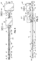
- the dispensing apparatus 240 shown in FIGS. 5 and 6 includes a first dispensing module 248 and a second dispensing module 250 arranged in series along the machine direction 46.
- the first dispensing module 248 of this embodiment includes a first dispensing nozzle 242 that is a SureWrap® nozzle commercially available from Nordson Corporation of Westlake, Ohio, which is described in U.S. Patent No. 7,578,882 to Harris et al. , the entire disclosure of which is hereby incorporated by reference herein.
- the second dispensing module 250 of this embodiment includes a second dispensing nozzle such as the UniversalTM CF nozzle commercially available from Nordson Corporation of Westlake, Ohio.
- the first dispensing nozzle 242 applies a first quantity 256 of adhesive formed by a filament impacted by a plurality of air jets to each elastic strand 28.
- the elastic strands 28 move faster than the first quantity 256 of adhesive, which causes the quantity 256 to stretch out during application onto the strands 28.
- this stretching of the first quantity 256 tends to separate or break the adhesive 30 into discrete localized increased masses 74 on the strands 28 that are separated from one another by thinner areas 76 of adhesive 30 running between adjacent masses 74.
- the thinner areas 76 may also break between adjacent increased masses 74, leaving no adhesive 30 between adjacent masses 74.
- Each of these discrete masses 74 of adhesive becomes a discrete bond point when the elastic strands 28 are adhered to the substrate 18.
- the second dispensing nozzle 244 applies a second quantity 258 of adhesive, which is a swirled filament of adhesive 30, onto all of the elastic strands 28 collectively.
- the first dispensing nozzle 242 applies adhesive individually onto each elastic strand 28, while the second dispensing nozzle 244 applies adhesive collectively onto all of the elastic strands 28.
- the first and second dispensing modules 248, 250 receive adhesive material from corresponding adhesive supplies 252, 254.
- the adhesive supplies 252, 254 may include separate individually adjustable pumps for each dispensing module 248, 250 or a shared dual stream pump for both dispensing modules 248, 250.
- the first dispensing nozzle 242 dispenses the first quantity 256 onto the first and third portions 32, 36 of the elastic strands 28, while the second dispensing nozzle 244 dispenses the second quantity 258 onto the second portions 34 of the elastic strands 28 only.
- the first and third portions 32, 36 are coated with first and third volumes of adhesive 30a, 30c that are larger than a second volume of adhesive 30b coating the second portions 34.
- the dispensing apparatus 240 advantageously applies a higher volume of adhesive 30 to the end portions 32, 36 of the elastic strands 28 than to the central portions 34, thereby significantly reducing adhesive use while maintaining similar high bond quality.
- FIG. 7 yet another embodiment of a dispensing apparatus 340 for applying varying volumes of adhesive along the length of elastic strands 28 in accordance with the invention is shown. Similar to the previous embodiment, the dispensing apparatus 340 shown in FIG. 7 includes a first dispensing module 348 and a second dispensing module 350 arranged in series along the machine direction 46.
- the first dispensing module 348 of this embodiment includes a SureWrap® nozzle commercially available from Nordson Corporation of Westlake, Ohio, which is described in U.S. Patent No. 7,578,882 to Harris et al .
- the second dispensing module 350 of this embodiment includes a non-contact swirl nozzle such as the SummittTM Mini Swirl nozzle commercially available from Nordson Corporation of Westlake, Ohio, which is described in U.S. Patent No. 4,815,660 to Boger .
- the first dispensing module 348 applies a first quantity 356 of adhesive formed by a filament impacted by a plurality of air jets to each elastic strand 28.
- the elastic strands 28 move faster than the first quantity 356 of adhesive, which causes the first quantity 356 to stretch out during application into discrete localized increased masses 74 on the strands 28 that are separated from one another by thinner (or broken) areas 76 of adhesive 30 running between adjacent masses 74.
- the second dispensing module 350 applies a second quantity 358 of adhesive, which is a miniature swirled filament of adhesive 30, onto each elastic strand 28 individually.
- each of the first and second dispensing modules 348, 350 in this embodiment apply adhesive 30 individually onto each elastic strand 28.
- the first and second dispensing modules 348, 350 receive adhesive material from corresponding adhesive supplies 352, 354.
- the adhesive supplies 352, 354 may include separate individually adjustable pumps for each dispensing module 348, 350 or a shared dual stream pump for both dispensing modules 348, 350.
- the first dispensing module 348 dispenses the first quantity 356 onto the first and third portions 32, 36 of the elastic strands 28, while the second dispensing module 350 dispenses the second quantity 358 onto the second portions 34 of the elastic strands 28 only.
- the first and third portions 32, 36 are coated with first and third volumes of adhesive 30a, 30c that are larger than a second volume of adhesive 30b coating the second portions 34.
- the dispensing apparatus 340 advantageously applies a higher volume of adhesive 30 to the end portions 32, 36 of the elastic strands 28 than to the central portions 34, thereby significantly reducing adhesive use while maintaining similar high bond quality.
- the dispensing apparatus 440 shown in FIG. 8 includes a first dispensing module 448 and a second dispensing module 450 arranged in series along the machine direction 46.
- the first dispensing module 448 of this embodiment includes a non-contact swirl nozzle such as the UniversalTM CF nozzle commercially available from Nordson Corporation of Westlake, Ohio.
- the second dispensing module 450 of this embodiment also includes a non-contact swirl nozzle such as the UniversalTM CF nozzle commercially available from Nordson Corporation of Westlake, Ohio.
- the first dispensing module 448 applies a first quantity 456 of adhesive which is formed by a filament swirled by air jets onto all of the elastic strands 28 collectively.
- the second dispensing module 450 applies a second quantity 458 of adhesive which is formed by a filament swirled by air jets onto all of the elastic strands 28 collectively.
- each of the first and second dispensing modules 448, 450 in this embodiment apply adhesive 30 collectively onto all of the elastic strands 28.
- the first and second dispensing modules 448, 450 receive adhesive material from corresponding adhesive supplies 452, 454.
- the adhesive supplies 452, 454 may include separate individually adjustable pumps for each dispensing module 448, 450 or a shared dual stream pump for both dispensing modules 448, 450.
- the first dispensing module 448 dispenses the first quantity 456 onto the first and third portions 32, 36 of the elastic strands 28, while the second dispensing module 450 dispenses the second quantity 458 onto the second portions 34 of the elastic strands 28.
- the first and third portions 32, 36 are coated with first and third volumes of adhesive 30a, 30c that are larger than a second volume of adhesive 30b coating the second portions 34.
- the dispensing apparatus 440 advantageously applies a higher volume of adhesive 30 to the end portions 32, 36 of the elastic strands 28 than to the central portions 34, thereby significantly reducing adhesive use while maintaining similar high bond quality.
- the dispensing apparatus 540 shown in FIG. 9 includes a first dispensing module 548 and a second dispensing module 550 arranged in series along the machine direction 46.
- the first dispensing module 548 of this embodiment includes a non-contact swirl nozzle such as the SummittTM Mini Swirl nozzle commercially available from Nordson Corporation of Westlake, Ohio.
- the second dispensing module 550 of this embodiment includes a non-contact swirl nozzle such as the UniversalTM CF nozzle commercially available from Nordson Corporation of Westlake, Ohio.
- the first dispensing module 548 applies a first quantity 556 of adhesive, which is a miniature swirled filament of adhesive 30, onto each elastic strand 28 individually.
- the second dispensing module 550 applies a second quantity 558 of adhesive, which is formed by a filament swirled by air jets onto all of the elastic strands 28 collectively.
- the first dispensing module 548 applies adhesive collectively onto all of the elastic strands 28, while the second dispensing module 550 applies adhesive individually onto each elastic strand 28.
- the first and second dispensing modules 548, 550 receive adhesive material from corresponding adhesive supplies 552, 554. Similar to the embodiments described above, the adhesive supplies 552, 554 may include separate individually adjustable pumps for each dispensing module 548, 550 or a shared dual stream pump for both dispensing modules 548, 550. Similar to the previous embodiment, the first dispensing module 548 dispenses the first quantity 556 onto the first and third portions 32, 36 of the elastic strands 28, while the second dispensing module 550 dispenses the second quantity 558 onto the second portions 34 of the elastic strands 28. Thus, as shown by the adhesive patterns shown in FIG.
- the first and third portions 32, 36 are coated with first and third volumes of adhesive 30a, 30c that are larger than a second volume of adhesive 30b coating the second portions 34.
- the dispensing apparatus 540 advantageously applies a higher volume of adhesive 30 to the end portions 32, 36 of the elastic strands 28 than to the central portions 34, thereby significantly reducing adhesive use while maintaining similar high bond quality.
- the dispensing apparatus 570 shown in FIG. 10 includes a first dispensing module 578 and a second dispensing module 580 arranged in series along the machine direction 46.
- the first dispensing module 578 of this embodiment includes a non-contact swirl nozzle such as the SummittTM Mini Swirl nozzle commercially available from Nordson Corporation of Westlake, Ohio.
- the second dispensing module 580 of this embodiment also includes a non-contact swirl nozzle such as the SummittTM Mini Swirl nozzle commercially available from Nordson Corporation of Westlake, Ohio.
- the first dispensing module 578 applies a first quantity 586 of adhesive, which is a miniature swirled filament of adhesive 30, onto each elastic strand 28 individually.
- the second dispensing module 580 applies a second quantity 588 of adhesive, which is a miniature swirled filament of adhesive 30, onto each elastic strand 28 individually.
- each of the first dispensing module 578 and the second dispensing module 580 applies adhesive individually onto each elastic strand 28.
- the first and second dispensing modules 578, 580 receive adhesive material from corresponding adhesive supplies 582, 584.
- the adhesive supplies 582, 584 may include separate individually adjustable pumps for each dispensing module 578, 580 or a shared dual stream pump for both dispensing modules 578, 580.
- the first dispensing module 578 dispenses the first quantity 586 onto the first and third portions 32, 36 of the elastic strands 28, while the second dispensing module 580 dispenses the second quantity 588 onto the second portions 34 of the elastic strands 28.
- the first and third portions 32, 36 are coated with first and third volumes of adhesive 30a, 30c that are larger than a second volume of adhesive 30b coating the second portions 34.
- the dispensing apparatus 570 advantageously applies a higher volume of adhesive 30 to the end portions 32, 36 of the elastic strands 28 than to the central portions 34, thereby significantly reducing adhesive use while maintaining similar high bond quality.
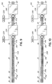
- FIGS. 11 and 12A show another embodiment of a dispensing apparatus 640 according to the invention.
- a first dispensing module 648 and a second dispensing module 650 are arranged generally in parallel along the machine direction 46 defined by the movement of the elastic strands 28.
- the first and second dispensing modules 648, 650 include corresponding first and second dispensing nozzles 642, 644 that are non-contact swirl nozzles such as the UniversaTM CF nozzle commercially available from Nordson Corporation of Westlake, Ohio.
- the first and second dispensing nozzles 642, 644 apply respective first and second quantities 656, 658 of adhesive simultaneously onto the first portion 32 and then the third portion 36 of the plurality of elastic strands 28.
- the first dispensing nozzle 642 dispenses the first quantity 656 onto the first and third portions 32, 36 of the strands 28, while the second dispensing nozzle 644 dispenses the second quantity 658 onto the first, second, and third portions 32, 34, 36.
- the first and third portions 32, 36 are coated with first and third volumes of adhesive 30a, 30c, respectively, that are larger than a second volume of adhesive 30b coating the second portion 34.
- any of the embodiments of the dispensing apparatus shown herein may dispense overlapping quantities of adhesive 30 onto the first and third portions 32, 36 as shown in FIGS. 11 and 12A , or may dispense a completely separate first quantity on the first and third portions 32, 36 and a second quantity on the second portions 34 as shown in FIGS. 2 through 10 .
- first dispensing nozzle 642 receives adhesive material pumped from a first adhesive supply 652 and the second dispensing nozzle 644 receives adhesive material pumped from a second adhesive supply 654.
- first and second adhesive supplies 652, 654 may be separate individually adjustable pumps or may be the two output streams of a single dual stream pump. It will be understood that the first and second dispensing nozzles 642, 644 may be the same type of dispensing nozzle or different types of dispensing nozzles in various embodiments in accordance with the invention.
- the simultaneous dispensing of the first and second quantities 656, 658 of adhesive is schematically shown from a front view in FIG. 12A .
- Each of the first and second dispensing nozzles 642, 644 may include corresponding first and second adhesive outlets 680, 682 that are angled slightly towards one another.
- the first and second quantities 656, 658 may entangle together slightly as they swirl towards the plurality of elastic strands 28.
- the dispensing apparatus 640 advantageously applies more volume of adhesive to the end portions 32, 36 of the elastic strands 28 than to the central portion 34, thereby significantly reducing adhesive use while maintaining similar high bond quality.
- first and second dispensing modules 648, 650 and the first and second adhesive outlets 680, 682 are shown as directly parallel along the machine direction 46 in FIGS. 11 and 12A
- another slightly modified embodiment of the dispensing apparatus 740 may include slightly offset elements along the machine direction 46.
- this dispensing apparatus 740 again includes first and second dispensing modules 748, 750 having first and second dispensing nozzles 742, 744 with first and second adhesive outlets 780, 782.
- the first dispensing module 748 is slightly offset forwards from the second dispensing module 750, which reduces or eliminates the entanglement of first and second filaments 756, 758 of adhesive during flight to the elastic strands 28.
- the dispensing apparatus 740 of FIG. 12B operates in an identical manner as the dispensing apparatus 640 of FIGS. 11 and 12A , and thus no further explanation is provided here.
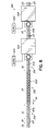
- FIGS. 13-17 illustrate various embodiments of a dispensing apparatus 840, 940, 1040 that only include a single dispensing module and a single dispensing nozzle.
- These single module embodiments may include various types of dispensing nozzles, as described in further detail below.
- FIG. 13 another embodiment of a dispensing apparatus 840 for applying varying volumes of adhesive along the length of elastic strands 28 in accordance with the invention is shown.
- the dispensing apparatus 840 shown in FIG. 13 includes only a single dispensing module 848.
- the dispensing module 848 of this embodiment includes a contact dispensing nozzle 842 as described in U.S. Patent Application No. 61/474,129 to Saine . More particularly, and as described in further detail in U.S. Patent Application No.
- the dispensing nozzle 848 applies a quantity 856, 858 of adhesive, which is a quantity applied by contacting the elastic strand 28 with an extruded adhesive 30 and then blowing air onto the elastic strand 28 to spread the adhesive 30 around the elastic strand 28.
- the dispensing nozzle 842 applies adhesive 30 individually onto each elastic strand 28.
- the quantity 856, 858 includes a first adhesive portion 856 that is thicker or includes more adhesive 30 than a second adhesive portion 858, as described in further detail below.
- the dispensing module 848 receives adhesive from two adhesive supplies 852, 854. Similar to the embodiments described above, the adhesive supplies 852, 854 may include separate individually adjustable pumps or a shared dual stream pump, depending on the particular application.
- the dispensing module 848 includes first and second valves 890, 892 configured to control whether a dispensing outlet 880 of the dispensing nozzle 842 receives adhesive from one, both, or neither of the adhesive supplies 852, 854.
- One alternative arrangement of the first and second valves 890, 892 is shown in FIG. 14
- another arrangement of the first and second valves 890a, 892a is shown in FIG. 15 . It will be understood that the particular arrangement of the valves 890, 892 may be modified in other manners without departing from the scope of the invention.
- the first valve 890 is positioned in a first angled passage 894 that receives adhesive 30 from the first adhesive supply 852.
- the second valve 892 is positioned in a second angled passage 896 receiving adhesive 30 from the second adhesive supply 854.
- Each of the first and second angled passages 894, 896 terminates in close proximity to the dispensing outlet 880, which is advantageous because this arrangement limits the passage space between the shutoff valves 890, 892 and the dispensing outlet 880.
- the amount of adhesive 30 that may drip or leak out of the dispensing nozzle 842 after the valves 890, 892 are closed is minimized.
- first and second valves 890, 892 are arranged in parallel within the dispensing module 848 such that each valve 890, 892 independently controls the on/off supply of adhesive 30 from the corresponding adhesive supplies 852, 854.
- This parallel arrangement of valves 890, 892 is similar to that arrangement which is described in U.S. Patent No. 7,152,815 to Harris et al. , the entire disclosure of which is hereby incorporated by reference herein.
- both of the valves 890, 892 are open, a maximum flow of adhesive 30 is extruded through the dispensing outlet 880.
- a lesser flow of adhesive 30 is extruded through the dispensing outlet 880.
- the relative thickness of the coating formed by the quantity 856, 858 may be modified.
- the dispensing module 848 opens both valves 890, 892 to apply a thicker first adhesive portion 856 at the first and third portions 32, 36 of the elastic strands 28.
- the dispensing module 848 then closes one of the valves 890, 892 to apply a thinner second adhesive portion 858 at the second portion 34 of the elastic strands 28.
- both valves 890, 892 are closed, substantially no adhesive 30 is extruded onto the elastic strands 28, such as for example at the free ends 38.
- the first and third portions 32, 36 are coated with first and third volumes of adhesive 30a, 30c that are larger than a second volume of adhesive 30b coating the second portions 34.
- the dispensing apparatus 840 advantageously applies a higher volume of adhesive 30 to the end portions 32, 36 of the elastic strands 28 than to the central portions 34, thereby significantly reducing adhesive use while maintaining similar high bond quality.
- FIG. 15 an alternative arrangement of the first and second valves 890a, 892a is shown.
- the first valve 890a and the second valve 892a are arranged in series within the dispensing module 848.
- the first valve 890a is positioned in a first passage 894a that receives adhesive 30 from the first adhesive supply 852.
- the second valve 892a is positioned in a second passage 896a receiving adhesive 30 from the second adhesive supply 854.
- the first passage 894a terminates into the second passage 896a just upstream of the second valve 892a.
- the second valve 892a operates to control on/off flow of both adhesive supplies 852, 854 into the dispensing outlet 880 simultaneously, while the first valve 890a only controls whether the flow past the second valve 892a originates from one or two adhesive supplies 852, 854.
- valves 890a, 892a again causes a maximum flow of adhesive 30 to be extruded through the dispensing outlet 880.
- a lesser flow of adhesive 30 is extruded through the dispensing outlet 880.
- the valve arrangement shown in FIG. 15 is operable to produce the same advantageous pattern of adhesive on the elastic strands 28 as described in regard to FIGS. 13 and 14 .
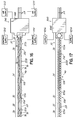
- FIG. 16 another embodiment of a dispensing apparatus 940 for applying varying volumes of adhesive along the length of elastic strands 28 in accordance with the invention is shown.
- the dispensing apparatus 940 shown in FIG. 16 includes only a single dispensing module 948.
- the dispensing module 948 of this embodiment includes a SureWrap® nozzle commercially available from Nordson Corporation of Westlake, Ohio. More particularly, the dispensing nozzle applies a quantity 956, 958 of adhesive formed by a filament impacted by a plurality of air jets to each elastic strand 28.
- the elastic strands 28 move faster than the quantity 956, 958 of adhesive, which causes the quantity 956, 958 to stretch out during application into discrete localized increased masses 74 on the strands 28 that are separated from one another by thinner (or broken) areas 76 of adhesive 30 running between adjacent masses 74.
- the dispensing module 948 applies adhesive 30 individually onto each elastic strand 28.
- the quantity 956, 958 includes a first adhesive portion 956 that includes more adhesive 30 than a second adhesive portion 958, as indicated schematically by closer spaced masses 74 of adhesive 30 in the first adhesive portion 956.
- the dispensing module 948 receives adhesive from two adhesive supplies 952, 954. Similar to the embodiments described above, the adhesive supplies 952, 954 may include separate individually adjustable pumps or a shared dual stream pump, depending on the particular application.
- the dispensing module 948 includes first and second valves (not shown) configured to control whether a dispensing outlet (not shown) of the dispensing nozzle receives adhesive from one, both, or neither of the adhesive supplies 952, 954, as described above. Additionally, the dispensing module 948 also receives pressurized process air from two air supplies 953, 955. The pressurized air from these air supplies 953, 955 may be selectively controlled by similar valves as the adhesive 30, as well understood in the art.
- the dispensing apparatus 940 advantageously applies more volume of adhesive to the end portions 32, 36 of the elastic strands 28 than to the central portion 34, thereby significantly reducing adhesive use while maintaining similar high bond quality.
- FIG. 17 still another embodiment of a dispensing apparatus 1040 for applying varying volumes of adhesive along the length of elastic strands 28 in accordance with the invention is shown.
- the dispensing apparatus 1040 shown in FIG. 17 includes only a single dispensing module 1048.
- the dispensing module 1048 of this embodiment includes a UniversalTM CF nozzle commercially available from Nordson Corporation of Westlake, Ohio. More particularly, the dispensing nozzle applies a quantity 1056, 1058 of adhesive formed by a swirled filament to all of the elastic strands 28 collectively.
- the quantity 1056, 1058 includes a first adhesive portion 1056 that includes more adhesive 30 than a second adhesive portion 1058, as indicated schematically by thicker and thinner swirl patterns shown in FIG. 17 .
- the dispensing module 1048 receives adhesive from two adhesive supplies 1052, 1054. Similar to the embodiments described above, the adhesive supplies 1052, 1054 may include separate individually adjustable pumps or a shared dual stream pump, depending on the particular application.
- the dispensing module 1048 includes first and second valves (not shown) configured to control whether a dispensing outlet (not shown) of the dispensing nozzle receives adhesive from one, both, or neither of the adhesive supplies 1052, 1054, as described above. When both valves are open, the dispensing module 1048 applies the thicker first adhesive portion 1056 to the elastic strands 28.
- the dispensing module 1048 applies the thinner second adhesive portion 1058 to the elastic strands 28.
- the dispensing apparatus 1040 advantageously applies more volume of adhesive to the end portions 32, 36 of the elastic strands 28 than to the central portion 34, thereby significantly reducing adhesive use while maintaining similar high bond quality.
- a method of dispensing adhesive onto a stretched elastic strand includes applying a first volume of adhesive onto a first portion of the elastic strand, applying a second volume of adhesive onto a second portion of the elastic strand, and applying a third volume of adhesive onto a third portion of the elastic strand.
- the second volume is less than the first and third volumes.
Landscapes
- Health & Medical Sciences (AREA)
- Engineering & Computer Science (AREA)
- Life Sciences & Earth Sciences (AREA)
- Biomedical Technology (AREA)
- Heart & Thoracic Surgery (AREA)
- Vascular Medicine (AREA)
- Epidemiology (AREA)
- Animal Behavior & Ethology (AREA)
- General Health & Medical Sciences (AREA)
- Public Health (AREA)
- Veterinary Medicine (AREA)
- Manufacturing & Machinery (AREA)
- Absorbent Articles And Supports Therefor (AREA)
- Application Of Or Painting With Fluid Materials (AREA)
- Coating Apparatus (AREA)
Applications Claiming Priority (1)
| Application Number | Priority Date | Filing Date | Title |
|---|---|---|---|
| US13/444,126 US9034425B2 (en) | 2012-04-11 | 2012-04-11 | Method and apparatus for applying adhesive on an elastic strand in a personal disposable hygiene product |
Publications (3)
| Publication Number | Publication Date |
|---|---|
| EP2679313A2 true EP2679313A2 (de) | 2014-01-01 |
| EP2679313A3 EP2679313A3 (de) | 2015-03-04 |
| EP2679313B1 EP2679313B1 (de) | 2018-11-21 |
Family
ID=49118282
Family Applications (1)
| Application Number | Title | Priority Date | Filing Date |
|---|---|---|---|
| EP13163420.6A Not-in-force EP2679313B1 (de) | 2012-04-11 | 2013-04-11 | Verfahren und Vorrichtung zum Auftragen von Leim auf einem elastischen Faden in einem Einweghygieneprodukt |
Country Status (4)
| Country | Link |
|---|---|
| US (5) | US9034425B2 (de) |
| EP (1) | EP2679313B1 (de) |
| JP (3) | JP2013215580A (de) |
| CN (4) | CN107051776A (de) |
Cited By (6)
| Publication number | Priority date | Publication date | Assignee | Title |
|---|---|---|---|---|
| WO2016025254A1 (en) * | 2014-08-11 | 2016-02-18 | Nordson Corporation | Method for applying adhesive on an elastic strand in assembly of a personal disposable hygiene product |
| US9682392B2 (en) | 2012-04-11 | 2017-06-20 | Nordson Corporation | Method for applying varying amounts or types of adhesive on an elastic strand |
| EP3210675A1 (de) * | 2016-02-25 | 2017-08-30 | Nordson Corporation | Verfahren, vorrichtung und düse zur applikation unterschiedlicher mengen oder arten von klebstoff auf einen elastischen faden |
| US9907705B2 (en) | 2012-04-11 | 2018-03-06 | Nordson Corporation | Dispensing apparatus for applying adhesive on an elastic strand in assembly of a personal disposable hygiene product |
| US11229556B2 (en) | 2016-01-29 | 2022-01-25 | Daio Paper Corporation | Stretchable structure for absorbent article, and method for producing same |
| CN117084866A (zh) * | 2015-01-16 | 2023-11-21 | 宝洁公司 | 包括具有通道的吸收芯的成人一次性吸收制品的系列 |
Families Citing this family (21)
| Publication number | Priority date | Publication date | Assignee | Title |
|---|---|---|---|---|
| US10704254B2 (en) | 2014-02-18 | 2020-07-07 | 3M Innovative Properties Company | Easy to apply air and water barrier articles |
| US11338311B2 (en) | 2014-04-01 | 2022-05-24 | Illinois Tool Works Inc. | Fluid application device having a nozzle with individually metered orifice or orifices |
| US11731394B2 (en) | 2014-12-22 | 2023-08-22 | 3M Innovative Properties Company | Air and water barrier articles |
| US20160256889A1 (en) | 2015-03-06 | 2016-09-08 | Nordson Corporation | Variable output dispensing applicator and associated methods of dispensing |
| US9415415B1 (en) | 2015-03-06 | 2016-08-16 | Nordson Corporation | Liquid dividing module for variable output dispensing applicator and associated methods |
| WO2017031275A1 (en) | 2015-08-18 | 2017-02-23 | 3M Innovative Properties Company | Self-sealing articles including elastic porous layer |
| EP3393791A4 (de) | 2015-12-22 | 2020-01-29 | 3M Innovative Properties Company | Walze mit luft- und wasserbarriereartikel und verfahren zur verwendung davon |
| JP6108372B1 (ja) | 2016-01-29 | 2017-04-05 | 大王製紙株式会社 | 吸収性物品の伸縮構造及びその製造方法 |
| CN108697540B (zh) | 2016-03-28 | 2020-05-12 | 金伯利-克拉克环球有限公司 | 用于施加弹性股线的方法 |
| CN107309137B (zh) * | 2016-04-27 | 2019-10-08 | 四川理工学院 | 铝合金型材异型孔底面静音材料涂抹装置 |
| JP6429830B2 (ja) * | 2016-05-30 | 2018-11-28 | ユニ・チャーム株式会社 | 吸収性物品の製造方法及び接着剤の塗布装置 |
| JP1571143S (de) * | 2016-07-27 | 2017-03-06 | ||
| JPWO2018066720A1 (ja) * | 2016-10-05 | 2018-10-04 | 株式会社サンツール | 伸縮性複合シート、伸縮性複合シートの製造方法および伸縮性複合シートの製造装置 |
| CN110139632B (zh) * | 2016-12-27 | 2022-10-28 | 尤妮佳股份有限公司 | 用于吸收性物品的片状构件的制造方法和制造设备 |
| US11365328B2 (en) | 2017-02-23 | 2022-06-21 | 3M Innovative Properties Company | Air and water barrier article including inelastic porous layer |
| WO2018209629A1 (en) | 2017-05-18 | 2018-11-22 | The Procter & Gamble Company | Absorbent article with belt having profiled elasticity |
| CN110573121B (zh) * | 2017-05-18 | 2023-04-14 | 宝洁公司 | 具有区域化弹性的束带的吸收制品 |
| WO2018236397A1 (en) | 2017-06-23 | 2018-12-27 | Kimberly-Clark Worldwide, Inc. | ADHESIVE PATTERN RESIDING ON A MOBILE BASE STRIP |
| EP3664938B1 (de) * | 2017-08-11 | 2025-01-15 | Illinois Tool Works Inc. | Vorrichtung und verfahren zur strangbeschichtung unterschiedlicher volumina |
| CN109551864A (zh) * | 2019-01-13 | 2019-04-02 | 贵州卡布国际生物科技有限公司 | 一种用于生产底膜的喷胶设备及其工艺流程 |
| EP4010184A1 (de) | 2019-08-07 | 2022-06-15 | 3M Innovative Properties Company | Band, artikel mit band und verbundschicht sowie zugehörige verfahren |
Citations (4)
| Publication number | Priority date | Publication date | Assignee | Title |
|---|---|---|---|---|
| US4785996A (en) | 1987-04-23 | 1988-11-22 | Nordson Corporation | Adhesive spray gun and nozzle attachment |
| US4815660A (en) | 1987-06-16 | 1989-03-28 | Nordson Corporation | Method and apparatus for spraying hot melt adhesive elongated fibers in spiral patterns by two or more side-by-side spray devices |
| US7152815B2 (en) | 2003-06-04 | 2006-12-26 | Nordson Corporation | Dispensing system, nozzle and method for independently dispensing and controlling liquid |
| US7578882B2 (en) | 2003-01-22 | 2009-08-25 | Nordson Corporation | Module, nozzle and method for dispensing controlled patterns of liquid material |
Family Cites Families (154)
| Publication number | Priority date | Publication date | Assignee | Title |
|---|---|---|---|---|
| US1529321A (en) | 1924-05-20 | 1925-03-10 | Pearson Susan Clare | Manicure implement |
| US2428284A (en) | 1943-08-18 | 1947-09-30 | Western Electric Co | Strand marking apparatus |
| US2823518A (en) | 1953-11-19 | 1958-02-18 | Thompson Prod Inc | Aircraft fuel pumping system |
| US3219276A (en) | 1962-10-16 | 1965-11-23 | Edward O Norris | Plural nozzles having intersecting spray and control therefor |
| US3640461A (en) | 1969-09-26 | 1972-02-08 | Hercules Inc | Apparatus and process for forming and spraying pesticidal invert emulsion |
| ZA74399B (en) | 1973-01-29 | 1975-02-26 | Fundemental & Applied Res Ltd | A device for the localized treatment of a continously running product by intermittent projection at very high pressure of a treating fluid |
| US3911173A (en) | 1973-02-05 | 1975-10-07 | Usm Corp | Adhesive process |
| DE2320488A1 (de) | 1973-04-21 | 1974-11-07 | Lutz & Ulmer | Vorrichtung zum behandeln von im wesentlichen eindimensionalem fasergut mit einer fluessigkeit |
| US3890926A (en) | 1974-07-25 | 1975-06-24 | Riegel Textile Corp | Apparatus for intermittently applying deposits of adhesive onto a moving web of material |
| US4050410A (en) | 1974-06-07 | 1977-09-27 | Hoechst Aktiengesellschaft | Apparatus for the manufacture of a series of photoconductor webs |
| US4325372A (en) | 1979-10-16 | 1982-04-20 | Riegel Textile Corporation | Elastic leg disposable diaper |
| US4789100A (en) | 1980-11-04 | 1988-12-06 | Adhesive Engineering Company | Multiple fluid pumping system |
| JPS58180601A (ja) | 1982-04-14 | 1983-10-22 | ユニ・チヤ−ム株式会社 | 使い捨ておむつ |
| US4488665A (en) | 1982-05-24 | 1984-12-18 | Spraymation, Inc. | Multiple-outlet adhesive applicator apparatus and method |
| US4476165A (en) | 1982-06-07 | 1984-10-09 | Acumeter Laboratories, Inc. | Method of and apparatus for multi-layer viscous fluid deposition such as for the application of adhesives and the like |
| FR2539274A1 (fr) | 1983-01-19 | 1984-07-20 | Boussac Saint Freres Bsf | Procede de fabrication de couches-culottes a jeter et couches-culottes obtenues |
| FR2542979B1 (fr) | 1983-03-25 | 1988-04-22 | Boussac Saint Freres Bsf | Procede de fabrication en continu de couches-culottes a jeter et couches-culottes obtenues |
| US4530862A (en) | 1983-04-29 | 1985-07-23 | Spraymation, Inc. | Control system and method for dispensing a liquid |
| US4764234A (en) | 1986-12-18 | 1988-08-16 | The Kendall Company | Method of applying adhesive |
| ES2042612T3 (es) | 1987-03-07 | 1993-12-16 | Fuller H B Licensing Financ | Procedimiento para la union permanente de elementos dilatables en forma de hilos o de cintas sobre un substrato superficial asi como utilizacion del mismo para la fabricacion de sectores de banda de hojas rizadas. |
| US4711683A (en) | 1987-03-09 | 1987-12-08 | Paper Converting Machine Company | Method and apparatus for making elastic diapers |
| US4891249A (en) | 1987-05-26 | 1990-01-02 | Acumeter Laboratories, Inc. | Method of and apparatus for somewhat-to-highly viscous fluid spraying for fiber or filament generation, controlled droplet generation, and combinations of fiber and droplet generation, intermittent and continuous, and for air-controlling spray deposition |
| US5876792A (en) | 1988-03-14 | 1999-03-02 | Nextec Applications, Inc. | Methods and apparatus for controlled placement of a polymer composition into a web |
| US4949668A (en) | 1988-06-16 | 1990-08-21 | Kimberly-Clark Corporation | Apparatus for sprayed adhesive diaper construction |
| JPH0649171B2 (ja) | 1988-07-04 | 1994-06-29 | 富士写真フイルム株式会社 | 塗布方法 |
| DE8901172U1 (de) | 1989-02-02 | 1990-06-07 | Nordson Corp., Westlake, Ohio | Vorrichtung zum Auftragen eines Klebestoffes auf elastische Fäden |
| US5030303A (en) | 1989-07-28 | 1991-07-09 | Nordson Corporation | Method for forming disposable garments with a waste containment pocket |
| US4995333A (en) | 1989-09-15 | 1991-02-26 | Kimberly-Clark Corporation | Sprayed adhesive system for applying a continuous filament of theroplastic material and imparting a swirling motion thereto |
| US5066428A (en) | 1990-08-08 | 1991-11-19 | Rusmar Incorporated | Foam generating apparatus |
| CA2050782C (en) | 1990-09-13 | 1997-01-28 | Takamitsu Igaue | Disposable garments and method for attachment of elastic members around leg-holes thereof |
| US5145689A (en) | 1990-10-17 | 1992-09-08 | Exxon Chemical Patents Inc. | Meltblowing die |
| US5322729A (en) | 1991-04-04 | 1994-06-21 | Ansell Edmont Industrial Inc. | Method and apparatus for producing a breathable coated fabric |
| CA2050023C (en) | 1991-04-22 | 2002-03-05 | Kimberly-Clark Worldwide, Inc. | Elongated element comprising helically patterned adhesive |
| DE69204170T2 (de) | 1991-11-01 | 1996-01-18 | Minnesota Mining & Mfg | Vorrichtung zum intermittierenden auftragen. |
| US5382312A (en) | 1992-04-08 | 1995-01-17 | Nordson Corporation | Dual format adhesive apparatus for intermittently disrupting parallel, straight lines of adhesive to form a band |
| US6696147B1 (en) | 1992-04-16 | 2004-02-24 | Thyssenkrupp Budd Company | Beaded adhesive and flanged part made therefrom |
| US5418009A (en) | 1992-07-08 | 1995-05-23 | Nordson Corporation | Apparatus and methods for intermittently applying discrete adhesive coatings |
| SE501940C2 (sv) | 1992-09-15 | 1995-06-26 | Moelnlycke Ab | Förfarande och anordning för att anbringa elastiska element på en långsträckt löpande materialbana |
| US5275676A (en) | 1992-09-18 | 1994-01-04 | Kimberly-Clark Corporation | Method and apparatus for applying a curved elastic to a moving web |
| CA2095555A1 (en) | 1992-12-16 | 1994-06-17 | Robert L. Popp | Apparatus and methods for selectively controlling a spray of liquid to form a distinct pattern |
| US5338569A (en) | 1993-04-14 | 1994-08-16 | Hatch J Mel | Process for coating dowels with water soluble glue |
| JPH0780377A (ja) * | 1993-09-17 | 1995-03-28 | Nireco Corp | 糊付け方法及び装置 |
| US5429694A (en) | 1994-04-05 | 1995-07-04 | Paragon Trade Brands, Inc. | Apparatus and method for applying tensioned elastic to material |
| US5525175A (en) | 1994-05-27 | 1996-06-11 | Kimberly-Clark Corporation | Apparatus and method for applying a curved elastic to a moving web |
| US5576091A (en) | 1994-08-16 | 1996-11-19 | Paragon Trade Brands, Inc. | Raised elasticized barrier for absorbent article |
| US5505995A (en) | 1995-02-02 | 1996-04-09 | Minnesota Mining And Manufacturing Company | Method and apparatus for coating substrates using an air knife |
| US5749971A (en) | 1996-03-28 | 1998-05-12 | Ni; Chong Yang | Apparatus for making a welding flux coating continously on a welding electrode |
| US5939136A (en) | 1996-04-12 | 1999-08-17 | Minnesota Mining And Manufacturing Company | Process for preparation of optical fiber devices using optical fibers with thermally removable coatings |
| US5688555A (en) | 1996-06-03 | 1997-11-18 | Taiwan Semiconductor Manufacturing Company Ltd | Gas barrier during edge rinse of SOG coating process to prevent SOG hump formation |
| IN195165B (de) | 1996-06-21 | 2005-01-28 | Engelhard Corp | |
| US5779799A (en) | 1996-06-21 | 1998-07-14 | Micron Technology, Inc. | Substrate coating apparatus |
| US5916524A (en) | 1997-07-23 | 1999-06-29 | Bio-Dot, Inc. | Dispensing apparatus having improved dynamic range |
| US6077373A (en) | 1996-09-11 | 2000-06-20 | Du Pont Canada Inc. | Manufacture of multilayer polymer films |
| US5916393A (en) | 1997-06-24 | 1999-06-29 | Owens Corning Fiberglas Technology, Inc. | Method for applying adhesive on a porous substrate |
| JP3972220B2 (ja) | 1997-07-25 | 2007-09-05 | ノードソン株式会社 | 接着剤のロール転写塗布方法 |
| US6033723A (en) | 1998-02-24 | 2000-03-07 | Imation Corp. | Method and apparatus for coating plurality of wet layers on flexible elongated web |
| US5992686A (en) | 1998-02-27 | 1999-11-30 | Fluid Research Corporation | Method and apparatus for dispensing liquids and solids |
| US6077375A (en) | 1998-04-15 | 2000-06-20 | Illinois Tool Works Inc. | Elastic strand coating process |
| US6296463B1 (en) | 1998-04-20 | 2001-10-02 | Nordson Corporation | Segmented metering die for hot melt adhesives or other polymer melts |
| US6422428B1 (en) | 1998-04-20 | 2002-07-23 | Nordson Corporation | Segmented applicator for hot melt adhesives or other thermoplastic materials |
| US6235137B1 (en) | 1998-08-06 | 2001-05-22 | Kimberly-Clark Worldwide, Inc. | Process for manufacturing an elastic article |
| US6652693B2 (en) | 1998-08-06 | 2003-11-25 | Kimberly-Clark Worldwide, Inc. | Process for applying adhesive in an article having a strand material |
| US6248097B1 (en) | 1998-08-06 | 2001-06-19 | Kimberly-Clark Worldwide, Inc. | Absorbent article with more conformable elastics |
| US6200635B1 (en) * | 1998-08-31 | 2001-03-13 | Illinois Tool Works Inc. | Omega spray pattern and method therefor |
| US6436216B1 (en) | 1999-01-29 | 2002-08-20 | Ato Findley, Inc. | Pre-packaging relaxation for laminated elastic webs |
| AU3328500A (en) | 1999-03-29 | 2000-10-16 | Kabushiki Kaisha Santuuru | Method and device for spiral spray coating |
| JP4457274B2 (ja) | 1999-04-23 | 2010-04-28 | ノードソン株式会社 | シール剤の塗布方法 |
| US6291016B1 (en) | 1999-06-02 | 2001-09-18 | Nordson Corporation | Method for increasing contact area between a viscous liquid and a substrate |
| US6478874B1 (en) | 1999-08-06 | 2002-11-12 | Engelhard Corporation | System for catalytic coating of a substrate |
| AU6781900A (en) | 1999-08-23 | 2001-03-19 | Andrew L. Gast-Bray | Apparatus and methods for coating non-horizontally supported sheet material |
| USD433692S (en) | 1999-11-02 | 2000-11-14 | Nordson Corporation | Swivable nozzle for dispensing adhesives and sealants |
| JP4090648B2 (ja) | 1999-11-18 | 2008-05-28 | 東京エレクトロン株式会社 | 膜形成方法及び膜形成装置 |
| US20010030014A1 (en) | 1999-11-30 | 2001-10-18 | Kui-Chiu Kwok | Elastic strand coating process |
| SE516892C2 (sv) | 1999-12-15 | 2002-03-19 | Btg Pulp And Paper Technology | Sätt och anordning för avlägsnande av kantöverskott vid bestrykning av löpande bana |
| US6579382B2 (en) | 2000-02-17 | 2003-06-17 | Kabushiki Kaisha Toshiba | Chemical liquid processing apparatus for processing a substrate and the method thereof |
| US6719846B2 (en) | 2000-03-14 | 2004-04-13 | Nordson Corporation | Device and method for applying adhesive filaments to materials such as strands or flat substrates |
| JP4474620B2 (ja) | 2000-03-14 | 2010-06-09 | ノードソン株式会社 | 糸状又は紐状物体に接着剤を塗布する装置と方法 |
| US6361634B1 (en) | 2000-04-05 | 2002-03-26 | Kimberly-Clark Worldwide, Inc. | Multiple stage coating of elastic strands with adhesive |
| US20060254698A1 (en) | 2000-04-08 | 2006-11-16 | Zuiko Corporation | Method for manufacturing disposable worn article |
| US6595977B1 (en) | 2000-04-20 | 2003-07-22 | Mcneil-Ppc, Inc. | Absorbent article having a high coefficient of friction backsheet and a self-release tape tab |
| JP3699331B2 (ja) * | 2000-05-26 | 2005-09-28 | ユニ・チャーム株式会社 | パンツ型の使い捨て着用物品 |
| US6378784B1 (en) | 2000-10-27 | 2002-04-30 | Nordson Corporation | Dispensing system using a die tip having an air foil |
| US7578812B2 (en) | 2001-03-01 | 2009-08-25 | Kimberly-Clark Worldwide, Inc. | Pre-fastened absorbent article having simplified fastening features |
| US6840404B1 (en) | 2001-03-08 | 2005-01-11 | Sealant Equipment & Engineering, Inc. | Metering system & methods |
| US6814555B2 (en) | 2001-03-09 | 2004-11-09 | Nordson Corporation | Apparatus and method for extruding single-component liquid strands into multi-component filaments |
| EP1243342B9 (de) | 2001-03-22 | 2010-02-17 | Nordson Corporation | Universal-Abgabesystem zum luftunterstütztem Schmelzspinnen von Flüssigkeitsfäden |
| US6619566B2 (en) | 2001-03-22 | 2003-09-16 | Nordson Corporation | Universal dispensing system for air assisted extrusion of liquid filaments |
| JP2002273299A (ja) | 2001-03-22 | 2002-09-24 | Fuji Photo Film Co Ltd | 塗布装置および塗布方法 |
| WO2002098572A1 (fr) | 2001-05-30 | 2002-12-12 | Kabushiki Kaisha Santuuru | Procede permettant de revetir d'adhesif un fil de caoutchouc et analogue sur une ligne d'enduction et dispositif de revetement d'adhesif |
| US20030089447A1 (en) | 2001-11-06 | 2003-05-15 | Kenneth Molee | Soft absorbent garment made with discretely coated elastic elements, and system and method for making a soft absorbent garment |
| US7118558B2 (en) * | 2001-11-06 | 2006-10-10 | Tyco Healthcare Retail Services Ag | Cloth-like laminate and absorbent garment |
| JP3732143B2 (ja) * | 2001-12-03 | 2006-01-05 | 花王株式会社 | 接着剤の塗工方法及び塗工装置 |
| CN1273103C (zh) * | 2001-12-21 | 2006-09-06 | 宝洁公司 | 具有用弹性线制成的外腿箍的一次性吸收制品 |
| GB0204390D0 (en) | 2002-02-26 | 2002-04-10 | Eastman Kodak Co | A method and system for coating |
| US6926772B2 (en) | 2002-02-27 | 2005-08-09 | 3M Innovative Properties Company | Strand coating device and method |
| US6936125B2 (en) | 2002-03-15 | 2005-08-30 | Nordson Corporation | Method of applying a continuous adhesive filament to an elastic strand with discrete bond points and articles manufactured by the method |
| US20050013975A1 (en) * | 2003-07-14 | 2005-01-20 | Nordson Corporation | Method of securing elastic strands to flat substrates and products produced by the method |
| US20030173024A1 (en) | 2002-03-15 | 2003-09-18 | Nordson Corporation | Method of securing elastic strands to flat substrates and products produced by the method |
| WO2003086949A2 (en) | 2002-04-12 | 2003-10-23 | Nordson Corporation | Applicator and nozzle for dispensing controlled patterns of liquid material |
| US6911232B2 (en) | 2002-04-12 | 2005-06-28 | Nordson Corporation | Module, nozzle and method for dispensing controlled patterns of liquid material |
| US20030224105A1 (en) | 2002-05-30 | 2003-12-04 | Symyx Technologies, Inc. | Apparatus and methods for forming films on substrates |
| US7521087B2 (en) | 2002-08-27 | 2009-04-21 | Basf Catalysts Llc | Method for catalyst coating of a substrate |
| US6905081B2 (en) | 2002-10-30 | 2005-06-14 | Nordson Corporation | Apparatus and methods for applying adhesive filaments onto one or more moving narrow substrates |
| US7462240B2 (en) | 2003-01-24 | 2008-12-09 | Nordson Corporation | Module, nozzle and method for dispensing controlled patterns of liquid material |
| US20040159672A1 (en) | 2003-01-31 | 2004-08-19 | Nordson Corporation | Apparatus and methods for recirculating liquid dispensing systems |
| US7172669B2 (en) | 2003-03-07 | 2007-02-06 | Sca Hygiene Products Ab | Method for applying elastic members on a pant-shaped absorbent article |
| JP4154668B2 (ja) | 2003-05-28 | 2008-09-24 | ノードソン株式会社 | 糸状体への接着剤塗布ノズル |
| US20050015050A1 (en) | 2003-07-15 | 2005-01-20 | Kimberly-Clark Worldwide, Inc. | Apparatus for depositing fluid material onto a substrate |
| US7201815B2 (en) | 2003-09-02 | 2007-04-10 | H.B. Fuller Licensing & Financing Inc. | Paper laminates manufactured using foamed adhesive systems |
| US7320814B2 (en) | 2003-12-19 | 2008-01-22 | Kimberly-Clark Worldwide, Inc. | Methods for applying a liquid to a web |
| US20050137549A1 (en) | 2003-12-22 | 2005-06-23 | Kimberly-Clark Worldwide, Inc. | Use of swirl-like adhesive patterns in the formation of absorbent articles |
| US7658811B2 (en) * | 2004-03-29 | 2010-02-09 | The Procter & Gamble Company | Letterpress application of elastomeric compositions |
| USD519536S1 (en) | 2004-04-14 | 2006-04-25 | Nordson Corporation | Nozzle holding portion of an adhesive dispenser |
| USD529321S1 (en) | 2004-05-06 | 2006-10-03 | Nordson Corporation | Liquid dispenser assembly and dispenser body portion |
| US20050271806A1 (en) | 2004-06-03 | 2005-12-08 | Nordson Corporation | Dispenser and method for non-contact dispensing of adhesive |
| US20060027944A1 (en) * | 2004-08-09 | 2006-02-09 | Rachelle Bentley | Apparatus and method for in-line manufacturing of disposable hygienic absorbent products and product produced by the apparatus and methods |
| US7465367B2 (en) | 2005-01-07 | 2008-12-16 | Innovative Elastics Limited | Process for forming a laminate |
| USD536354S1 (en) | 2005-01-27 | 2007-02-06 | Nordson Corporation | Liquid spray applicator device |
| GB0505873D0 (en) | 2005-03-22 | 2005-04-27 | Ten Cate Advanced Textiles Bv | Method of depositing materials on a textile substrate |
| US20060258249A1 (en) | 2005-05-11 | 2006-11-16 | Fairbanks Jason S | Elastic laminates and process for producing same |
| JPWO2007032060A1 (ja) | 2005-09-13 | 2009-03-19 | サンスター技研株式会社 | 高粘度材料の塗布装置 |
| US8153238B2 (en) | 2005-12-14 | 2012-04-10 | Kimberly-Clark Worldwide, Inc. | Stretch bonded laminate including an elastic member containing an adhesive composition |
| US7833369B2 (en) * | 2005-12-14 | 2010-11-16 | Kimberly-Clark Worldwide, Inc. | Strand, substrate, and/or composite comprising re-activatable adhesive composition, and processes for making and/or utilizing same |
| US7820001B2 (en) | 2005-12-15 | 2010-10-26 | Kimberly-Clark Worldwide, Inc. | Latent elastic laminates and methods of making latent elastic laminates |
| FR2902675B1 (fr) * | 2006-06-21 | 2008-09-12 | Lvmh Rech | Buse de distribution de produit de fluide et dispositif de distribution de produit de fluide comprenant une telle buse |
| ITTV20060123A1 (it) | 2006-07-17 | 2008-01-18 | Hip Mitsu Srl | Struttura di testata di spalmatura, particolarmente di uno o piu' adesivi o miscele di adesivi |
| US7798434B2 (en) | 2006-12-13 | 2010-09-21 | Nordson Corporation | Multi-plate nozzle and method for dispensing random pattern of adhesive filaments |
| USD550261S1 (en) | 2006-12-13 | 2007-09-04 | Nordson Corporation | Adhesive dispensing nozzle |
| US7703705B2 (en) | 2007-02-16 | 2010-04-27 | Nordson Corporation | Apparatus and method for dispensing a mixture of a gas and a fluid material |
| WO2008124498A1 (en) | 2007-04-03 | 2008-10-16 | Nordson Corporation | Protective member and nozzle assembly configured to resist wear |
| US10137472B2 (en) | 2007-04-06 | 2018-11-27 | Illinois Tool Works Inc. | Dual pattern shim assembly for use in conjunction with hot melt adhesive dispensing systems |
| US7908997B2 (en) * | 2007-06-04 | 2011-03-22 | Illinois Tool Works Inc. | Hybrid hot melt adhesive or other thermoplastic material dispensing system |
| DE102007034877A1 (de) | 2007-07-24 | 2009-01-29 | Schmid Rhyner Ag | Verfahren und Vorrichtung zum Auftrag von Kunststoffbeschichtungen |
| US20090062761A1 (en) * | 2007-08-30 | 2009-03-05 | Kimberly-Clark Worldwide, Inc. | Attachment Pattern for Undergarment Attached Absorbent Articles |
| JP2009082439A (ja) * | 2007-09-28 | 2009-04-23 | Uni Charm Corp | 吸収性物品 |
| USD588617S1 (en) | 2008-04-14 | 2009-03-17 | Nordson Corporation | Nozzle assembly |
| DE202008007386U1 (de) | 2008-06-03 | 2008-07-31 | Robatech Ag | Heissleim-Auftragsvorrichtung |
| EP2145695A1 (de) | 2008-07-14 | 2010-01-20 | Sika Technology AG | Vorrichtung zur Klebstoffapplikation |
| USD599388S1 (en) | 2008-09-18 | 2009-09-01 | Heitec-Heisskanaltechnik Gmbh | Hot runner flat nozzle |
| US20100221435A1 (en) | 2008-11-07 | 2010-09-02 | Palo Alto Research Center Incorporated | Micro-Extrusion System With Airjet Assisted Bead Deflection |
| DE102009013379A1 (de) | 2009-03-09 | 2010-09-16 | Wolfgang Klingel | Vorrichtung zum Beschichten eines Substrats |
| US8567342B2 (en) | 2009-05-22 | 2013-10-29 | Tokyo Ohka Kogyo Co., Ltd. | Coating device and coating method |
| USD641767S1 (en) | 2009-06-03 | 2011-07-19 | Focke & Co. (Gmbh & Co. Kg) | Glue nozzle |
| US20110012752A1 (en) | 2009-07-14 | 2011-01-20 | Illinois Tool Works Inc. | Wireless control for valve operating machine |
| US8551562B2 (en) | 2009-07-17 | 2013-10-08 | Illnois Tool Works Inc. | Method for metering hot melt adhesives with variable adhesive volumes |
| US8445061B2 (en) | 2009-07-17 | 2013-05-21 | Illinois Tool Works Inc. | Metering system for hot melt adhesives with variable adhesive volumes |
| DE102009034687B4 (de) | 2009-07-24 | 2017-03-30 | Windmöller & Hölscher Kg | Vorrichtung und Verfahren zum Versehen von Werkstücken oder Bahnen mit Leim |
| US9067236B2 (en) | 2009-10-05 | 2015-06-30 | Nordson Corporation | Two-component liquid dispenser gun and system |
| US8312833B2 (en) | 2009-12-10 | 2012-11-20 | Southern Taiwan University Of Technology | Pneumatic nozzle for roller coating |
| JP5830225B2 (ja) * | 2010-01-08 | 2015-12-09 | ユニ・チャーム株式会社 | 流体吐出装置 |
| US8186296B2 (en) | 2010-05-05 | 2012-05-29 | The Procter & Gamble Company | Methods and apparatus for applying adhesives in patterns to an advancing substrate |
| EP2696991B1 (de) | 2011-04-11 | 2016-09-14 | Nordson Corporation | System, düse und verfahren zur beschichtung von elastischen fasern |
| US9034425B2 (en) | 2012-04-11 | 2015-05-19 | Nordson Corporation | Method and apparatus for applying adhesive on an elastic strand in a personal disposable hygiene product |
| US20140261967A1 (en) | 2013-03-13 | 2014-09-18 | Nordson Corporation | Method of manufacturing a personal hygiene product |
-
2012
- 2012-04-11 US US13/444,126 patent/US9034425B2/en not_active Expired - Fee Related
-
2013
- 2013-04-11 JP JP2013082821A patent/JP2013215580A/ja active Pending
- 2013-04-11 CN CN201710060995.4A patent/CN107051776A/zh active Pending
- 2013-04-11 CN CN201710060975.7A patent/CN107008587A/zh active Pending
- 2013-04-11 EP EP13163420.6A patent/EP2679313B1/de not_active Not-in-force
- 2013-04-11 CN CN201310125239.7A patent/CN103372513B/zh not_active Expired - Fee Related
-
2014
- 2014-08-11 US US14/456,418 patent/US9067394B2/en not_active Expired - Fee Related
-
2015
- 2015-03-11 US US14/644,326 patent/US9962298B2/en not_active Expired - Fee Related
- 2015-03-11 US US14/644,318 patent/US9907705B2/en not_active Expired - Fee Related
- 2015-03-11 US US14/644,322 patent/US9155663B2/en not_active Expired - Fee Related
- 2015-08-05 JP JP2017507856A patent/JP2017526429A/ja not_active Abandoned
- 2015-08-05 CN CN201580043050.0A patent/CN106572932A/zh active Pending
-
2018
- 2018-06-06 JP JP2018108987A patent/JP2018158341A/ja not_active Abandoned
Patent Citations (4)
| Publication number | Priority date | Publication date | Assignee | Title |
|---|---|---|---|---|
| US4785996A (en) | 1987-04-23 | 1988-11-22 | Nordson Corporation | Adhesive spray gun and nozzle attachment |
| US4815660A (en) | 1987-06-16 | 1989-03-28 | Nordson Corporation | Method and apparatus for spraying hot melt adhesive elongated fibers in spiral patterns by two or more side-by-side spray devices |
| US7578882B2 (en) | 2003-01-22 | 2009-08-25 | Nordson Corporation | Module, nozzle and method for dispensing controlled patterns of liquid material |
| US7152815B2 (en) | 2003-06-04 | 2006-12-26 | Nordson Corporation | Dispensing system, nozzle and method for independently dispensing and controlling liquid |
Cited By (7)
| Publication number | Priority date | Publication date | Assignee | Title |
|---|---|---|---|---|
| US9682392B2 (en) | 2012-04-11 | 2017-06-20 | Nordson Corporation | Method for applying varying amounts or types of adhesive on an elastic strand |
| US9907705B2 (en) | 2012-04-11 | 2018-03-06 | Nordson Corporation | Dispensing apparatus for applying adhesive on an elastic strand in assembly of a personal disposable hygiene product |
| US9962298B2 (en) | 2012-04-11 | 2018-05-08 | Nordson Corporation | Dispensing apparatus for applying adhesive on an elastic strand in a personal disposable hygiene product |
| WO2016025254A1 (en) * | 2014-08-11 | 2016-02-18 | Nordson Corporation | Method for applying adhesive on an elastic strand in assembly of a personal disposable hygiene product |
| CN117084866A (zh) * | 2015-01-16 | 2023-11-21 | 宝洁公司 | 包括具有通道的吸收芯的成人一次性吸收制品的系列 |
| US11229556B2 (en) | 2016-01-29 | 2022-01-25 | Daio Paper Corporation | Stretchable structure for absorbent article, and method for producing same |
| EP3210675A1 (de) * | 2016-02-25 | 2017-08-30 | Nordson Corporation | Verfahren, vorrichtung und düse zur applikation unterschiedlicher mengen oder arten von klebstoff auf einen elastischen faden |
Also Published As
| Publication number | Publication date |
|---|---|
| CN106572932A (zh) | 2017-04-19 |
| JP2013215580A (ja) | 2013-10-24 |
| JP2018158341A (ja) | 2018-10-11 |
| US20130274700A1 (en) | 2013-10-17 |
| CN107051776A (zh) | 2017-08-18 |
| CN103372513B (zh) | 2017-03-01 |
| CN107008587A (zh) | 2017-08-04 |
| CN103372513A (zh) | 2013-10-30 |
| US9067394B2 (en) | 2015-06-30 |
| US9907705B2 (en) | 2018-03-06 |
| EP2679313A3 (de) | 2015-03-04 |
| JP2017526429A (ja) | 2017-09-14 |
| US20150182984A1 (en) | 2015-07-02 |
| US9155663B2 (en) | 2015-10-13 |
| US9034425B2 (en) | 2015-05-19 |
| US20150182385A1 (en) | 2015-07-02 |
| US20150182983A1 (en) | 2015-07-02 |
| EP2679313B1 (de) | 2018-11-21 |
| US9962298B2 (en) | 2018-05-08 |
| US20140345786A1 (en) | 2014-11-27 |
Similar Documents
| Publication | Publication Date | Title |
|---|---|---|
| US9034425B2 (en) | Method and apparatus for applying adhesive on an elastic strand in a personal disposable hygiene product | |
| US9682392B2 (en) | Method for applying varying amounts or types of adhesive on an elastic strand | |
| US6936125B2 (en) | Method of applying a continuous adhesive filament to an elastic strand with discrete bond points and articles manufactured by the method | |
| US20140261967A1 (en) | Method of manufacturing a personal hygiene product | |
| US20060251806A1 (en) | Method of securing elastic strands to flat substrates and apparatus therefor | |
| US20130240122A1 (en) | Method of manufacturing a personal hygiene product | |
| EP3210675A1 (de) | Verfahren, vorrichtung und düse zur applikation unterschiedlicher mengen oder arten von klebstoff auf einen elastischen faden | |
| CA2928604C (en) | Fluid application device having a modular nozzle assembly for applying fluid to an article | |
| JP4402894B2 (ja) | ストランド上に接着剤を分配する装置及び方法 | |
| WO2016025254A1 (en) | Method for applying adhesive on an elastic strand in assembly of a personal disposable hygiene product | |
| US20040081794A1 (en) | Method for applying adhesive filaments to multiple strands of material and articles formed with the method | |
| EP3068550B1 (de) | Flüssigkeitsauftragsvorrichtung mit modularer kontaktloser düse zum auftragen von flüssigkeit auf einen gegenstand |
Legal Events
| Date | Code | Title | Description |
|---|---|---|---|
| PUAI | Public reference made under article 153(3) epc to a published international application that has entered the european phase |
Free format text: ORIGINAL CODE: 0009012 |
|
| AK | Designated contracting states |
Kind code of ref document: A2 Designated state(s): AL AT BE BG CH CY CZ DE DK EE ES FI FR GB GR HR HU IE IS IT LI LT LU LV MC MK MT NL NO PL PT RO RS SE SI SK SM TR |
|
| AX | Request for extension of the european patent |
Extension state: BA ME |
|
| RIN1 | Information on inventor provided before grant (corrected) |
Inventor name: HARRIS, MICHAEL W. |
|
| PUAL | Search report despatched |
Free format text: ORIGINAL CODE: 0009013 |
|
| AK | Designated contracting states |
Kind code of ref document: A3 Designated state(s): AL AT BE BG CH CY CZ DE DK EE ES FI FR GB GR HR HU IE IS IT LI LT LU LV MC MK MT NL NO PL PT RO RS SE SI SK SM TR |
|
| AX | Request for extension of the european patent |
Extension state: BA ME |
|
| RIC1 | Information provided on ipc code assigned before grant |
Ipc: B05C 9/06 20060101ALI20150129BHEP Ipc: B05C 5/02 20060101AFI20150129BHEP Ipc: A61F 13/15 20060101ALI20150129BHEP Ipc: A61F 13/49 20060101ALI20150129BHEP |
|
| 17P | Request for examination filed |
Effective date: 20150904 |
|
| RBV | Designated contracting states (corrected) |
Designated state(s): AL AT BE BG CH CY CZ DE DK EE ES FI FR GB GR HR HU IE IS IT LI LT LU LV MC MK MT NL NO PL PT RO RS SE SI SK SM TR |
|
| STAA | Information on the status of an ep patent application or granted ep patent |
Free format text: STATUS: EXAMINATION IS IN PROGRESS |
|
| 17Q | First examination report despatched |
Effective date: 20170120 |
|
| GRAP | Despatch of communication of intention to grant a patent |
Free format text: ORIGINAL CODE: EPIDOSNIGR1 |
|
| STAA | Information on the status of an ep patent application or granted ep patent |
Free format text: STATUS: GRANT OF PATENT IS INTENDED |
|
| INTG | Intention to grant announced |
Effective date: 20170721 |
|
| GRAS | Grant fee paid |
Free format text: ORIGINAL CODE: EPIDOSNIGR3 |
|
| GRAJ | Information related to disapproval of communication of intention to grant by the applicant or resumption of examination proceedings by the epo deleted |
Free format text: ORIGINAL CODE: EPIDOSDIGR1 |
|
| GRAL | Information related to payment of fee for publishing/printing deleted |
Free format text: ORIGINAL CODE: EPIDOSDIGR3 |
|
| STAA | Information on the status of an ep patent application or granted ep patent |
Free format text: STATUS: EXAMINATION IS IN PROGRESS |
|
| INTC | Intention to grant announced (deleted) | ||
| RIN1 | Information on inventor provided before grant (corrected) |
Inventor name: HARRIS, MICHAEL W. |
|
| GRAP | Despatch of communication of intention to grant a patent |
Free format text: ORIGINAL CODE: EPIDOSNIGR1 |
|
| STAA | Information on the status of an ep patent application or granted ep patent |
Free format text: STATUS: GRANT OF PATENT IS INTENDED |
|
| INTG | Intention to grant announced |
Effective date: 20180112 |
|
| GRAJ | Information related to disapproval of communication of intention to grant by the applicant or resumption of examination proceedings by the epo deleted |
Free format text: ORIGINAL CODE: EPIDOSDIGR1 |
|
| GRAL | Information related to payment of fee for publishing/printing deleted |
Free format text: ORIGINAL CODE: EPIDOSDIGR3 |
|
| STAA | Information on the status of an ep patent application or granted ep patent |
Free format text: STATUS: EXAMINATION IS IN PROGRESS |
|
| GRAP | Despatch of communication of intention to grant a patent |
Free format text: ORIGINAL CODE: EPIDOSNIGR1 |
|
| STAA | Information on the status of an ep patent application or granted ep patent |
Free format text: STATUS: GRANT OF PATENT IS INTENDED |
|
| INTG | Intention to grant announced |
Effective date: 20180601 |
|
| GRAA | (expected) grant |
Free format text: ORIGINAL CODE: 0009210 |
|
| STAA | Information on the status of an ep patent application or granted ep patent |
Free format text: STATUS: THE PATENT HAS BEEN GRANTED |
|
| AK | Designated contracting states |
Kind code of ref document: B1 Designated state(s): AL AT BE BG CH CY CZ DE DK EE ES FI FR GB GR HR HU IE IS IT LI LT LU LV MC MK MT NL NO PL PT RO RS SE SI SK SM TR |
|
| REG | Reference to a national code |
Ref country code: CH Ref legal event code: EP |
|
| REG | Reference to a national code |
Ref country code: IE Ref legal event code: FG4D |
|
| REG | Reference to a national code |
Ref country code: DE Ref legal event code: R096 Ref document number: 602013046981 Country of ref document: DE |
|
| REG | Reference to a national code |
Ref country code: AT Ref legal event code: REF Ref document number: 1066947 Country of ref document: AT Kind code of ref document: T Effective date: 20181215 |
|
| REG | Reference to a national code |
Ref country code: NL Ref legal event code: MP Effective date: 20181121 |
|
| REG | Reference to a national code |
Ref country code: AT Ref legal event code: MK05 Ref document number: 1066947 Country of ref document: AT Kind code of ref document: T Effective date: 20181121 |
|
| PG25 | Lapsed in a contracting state [announced via postgrant information from national office to epo] |
Ref country code: IS Free format text: LAPSE BECAUSE OF FAILURE TO SUBMIT A TRANSLATION OF THE DESCRIPTION OR TO PAY THE FEE WITHIN THE PRESCRIBED TIME-LIMIT Effective date: 20190321 Ref country code: NO Free format text: LAPSE BECAUSE OF FAILURE TO SUBMIT A TRANSLATION OF THE DESCRIPTION OR TO PAY THE FEE WITHIN THE PRESCRIBED TIME-LIMIT Effective date: 20190221 Ref country code: AT Free format text: LAPSE BECAUSE OF FAILURE TO SUBMIT A TRANSLATION OF THE DESCRIPTION OR TO PAY THE FEE WITHIN THE PRESCRIBED TIME-LIMIT Effective date: 20181121 Ref country code: HR Free format text: LAPSE BECAUSE OF FAILURE TO SUBMIT A TRANSLATION OF THE DESCRIPTION OR TO PAY THE FEE WITHIN THE PRESCRIBED TIME-LIMIT Effective date: 20181121 Ref country code: LT Free format text: LAPSE BECAUSE OF FAILURE TO SUBMIT A TRANSLATION OF THE DESCRIPTION OR TO PAY THE FEE WITHIN THE PRESCRIBED TIME-LIMIT Effective date: 20181121 Ref country code: ES Free format text: LAPSE BECAUSE OF FAILURE TO SUBMIT A TRANSLATION OF THE DESCRIPTION OR TO PAY THE FEE WITHIN THE PRESCRIBED TIME-LIMIT Effective date: 20181121 Ref country code: BG Free format text: LAPSE BECAUSE OF FAILURE TO SUBMIT A TRANSLATION OF THE DESCRIPTION OR TO PAY THE FEE WITHIN THE PRESCRIBED TIME-LIMIT Effective date: 20190221 Ref country code: FI Free format text: LAPSE BECAUSE OF FAILURE TO SUBMIT A TRANSLATION OF THE DESCRIPTION OR TO PAY THE FEE WITHIN THE PRESCRIBED TIME-LIMIT Effective date: 20181121 Ref country code: LV Free format text: LAPSE BECAUSE OF FAILURE TO SUBMIT A TRANSLATION OF THE DESCRIPTION OR TO PAY THE FEE WITHIN THE PRESCRIBED TIME-LIMIT Effective date: 20181121 |
|
| PG25 | Lapsed in a contracting state [announced via postgrant information from national office to epo] |
Ref country code: AL Free format text: LAPSE BECAUSE OF FAILURE TO SUBMIT A TRANSLATION OF THE DESCRIPTION OR TO PAY THE FEE WITHIN THE PRESCRIBED TIME-LIMIT Effective date: 20181121 Ref country code: SE Free format text: LAPSE BECAUSE OF FAILURE TO SUBMIT A TRANSLATION OF THE DESCRIPTION OR TO PAY THE FEE WITHIN THE PRESCRIBED TIME-LIMIT Effective date: 20181121 Ref country code: RS Free format text: LAPSE BECAUSE OF FAILURE TO SUBMIT A TRANSLATION OF THE DESCRIPTION OR TO PAY THE FEE WITHIN THE PRESCRIBED TIME-LIMIT Effective date: 20181121 Ref country code: NL Free format text: LAPSE BECAUSE OF FAILURE TO SUBMIT A TRANSLATION OF THE DESCRIPTION OR TO PAY THE FEE WITHIN THE PRESCRIBED TIME-LIMIT Effective date: 20181121 Ref country code: PT Free format text: LAPSE BECAUSE OF FAILURE TO SUBMIT A TRANSLATION OF THE DESCRIPTION OR TO PAY THE FEE WITHIN THE PRESCRIBED TIME-LIMIT Effective date: 20190321 Ref country code: GR Free format text: LAPSE BECAUSE OF FAILURE TO SUBMIT A TRANSLATION OF THE DESCRIPTION OR TO PAY THE FEE WITHIN THE PRESCRIBED TIME-LIMIT Effective date: 20190222 |
|
| PG25 | Lapsed in a contracting state [announced via postgrant information from national office to epo] |
Ref country code: CZ Free format text: LAPSE BECAUSE OF FAILURE TO SUBMIT A TRANSLATION OF THE DESCRIPTION OR TO PAY THE FEE WITHIN THE PRESCRIBED TIME-LIMIT Effective date: 20181121 Ref country code: IT Free format text: LAPSE BECAUSE OF FAILURE TO SUBMIT A TRANSLATION OF THE DESCRIPTION OR TO PAY THE FEE WITHIN THE PRESCRIBED TIME-LIMIT Effective date: 20181121 Ref country code: PL Free format text: LAPSE BECAUSE OF FAILURE TO SUBMIT A TRANSLATION OF THE DESCRIPTION OR TO PAY THE FEE WITHIN THE PRESCRIBED TIME-LIMIT Effective date: 20181121 Ref country code: DK Free format text: LAPSE BECAUSE OF FAILURE TO SUBMIT A TRANSLATION OF THE DESCRIPTION OR TO PAY THE FEE WITHIN THE PRESCRIBED TIME-LIMIT Effective date: 20181121 |
|
| REG | Reference to a national code |
Ref country code: DE Ref legal event code: R097 Ref document number: 602013046981 Country of ref document: DE |
|
| PG25 | Lapsed in a contracting state [announced via postgrant information from national office to epo] |
Ref country code: EE Free format text: LAPSE BECAUSE OF FAILURE TO SUBMIT A TRANSLATION OF THE DESCRIPTION OR TO PAY THE FEE WITHIN THE PRESCRIBED TIME-LIMIT Effective date: 20181121 Ref country code: SM Free format text: LAPSE BECAUSE OF FAILURE TO SUBMIT A TRANSLATION OF THE DESCRIPTION OR TO PAY THE FEE WITHIN THE PRESCRIBED TIME-LIMIT Effective date: 20181121 Ref country code: RO Free format text: LAPSE BECAUSE OF FAILURE TO SUBMIT A TRANSLATION OF THE DESCRIPTION OR TO PAY THE FEE WITHIN THE PRESCRIBED TIME-LIMIT Effective date: 20181121 Ref country code: SK Free format text: LAPSE BECAUSE OF FAILURE TO SUBMIT A TRANSLATION OF THE DESCRIPTION OR TO PAY THE FEE WITHIN THE PRESCRIBED TIME-LIMIT Effective date: 20181121 |
|
| PLBE | No opposition filed within time limit |
Free format text: ORIGINAL CODE: 0009261 |
|
| STAA | Information on the status of an ep patent application or granted ep patent |
Free format text: STATUS: NO OPPOSITION FILED WITHIN TIME LIMIT |
|
| 26N | No opposition filed |
Effective date: 20190822 |
|
| PG25 | Lapsed in a contracting state [announced via postgrant information from national office to epo] |
Ref country code: SI Free format text: LAPSE BECAUSE OF FAILURE TO SUBMIT A TRANSLATION OF THE DESCRIPTION OR TO PAY THE FEE WITHIN THE PRESCRIBED TIME-LIMIT Effective date: 20181121 |
|
| REG | Reference to a national code |
Ref country code: DE Ref legal event code: R119 Ref document number: 602013046981 Country of ref document: DE |
|
| REG | Reference to a national code |
Ref country code: CH Ref legal event code: PL |
|
| REG | Reference to a national code |
Ref country code: BE Ref legal event code: MM Effective date: 20190430 |
|
| GBPC | Gb: european patent ceased through non-payment of renewal fee |
Effective date: 20190411 |
|
| PG25 | Lapsed in a contracting state [announced via postgrant information from national office to epo] |
Ref country code: LU Free format text: LAPSE BECAUSE OF NON-PAYMENT OF DUE FEES Effective date: 20190411 Ref country code: MC Free format text: LAPSE BECAUSE OF FAILURE TO SUBMIT A TRANSLATION OF THE DESCRIPTION OR TO PAY THE FEE WITHIN THE PRESCRIBED TIME-LIMIT Effective date: 20181121 |
|
| PG25 | Lapsed in a contracting state [announced via postgrant information from national office to epo] |
Ref country code: GB Free format text: LAPSE BECAUSE OF NON-PAYMENT OF DUE FEES Effective date: 20190411 Ref country code: CH Free format text: LAPSE BECAUSE OF NON-PAYMENT OF DUE FEES Effective date: 20190430 Ref country code: LI Free format text: LAPSE BECAUSE OF NON-PAYMENT OF DUE FEES Effective date: 20190430 Ref country code: DE Free format text: LAPSE BECAUSE OF NON-PAYMENT OF DUE FEES Effective date: 20191101 |
|
| PG25 | Lapsed in a contracting state [announced via postgrant information from national office to epo] |
Ref country code: FR Free format text: LAPSE BECAUSE OF NON-PAYMENT OF DUE FEES Effective date: 20190430 Ref country code: BE Free format text: LAPSE BECAUSE OF NON-PAYMENT OF DUE FEES Effective date: 20190430 |
|
| PG25 | Lapsed in a contracting state [announced via postgrant information from national office to epo] |
Ref country code: TR Free format text: LAPSE BECAUSE OF FAILURE TO SUBMIT A TRANSLATION OF THE DESCRIPTION OR TO PAY THE FEE WITHIN THE PRESCRIBED TIME-LIMIT Effective date: 20181121 |
|
| PG25 | Lapsed in a contracting state [announced via postgrant information from national office to epo] |
Ref country code: IE Free format text: LAPSE BECAUSE OF NON-PAYMENT OF DUE FEES Effective date: 20190411 |
|
| PG25 | Lapsed in a contracting state [announced via postgrant information from national office to epo] |
Ref country code: CY Free format text: LAPSE BECAUSE OF FAILURE TO SUBMIT A TRANSLATION OF THE DESCRIPTION OR TO PAY THE FEE WITHIN THE PRESCRIBED TIME-LIMIT Effective date: 20181121 |
|
| PG25 | Lapsed in a contracting state [announced via postgrant information from national office to epo] |
Ref country code: HU Free format text: LAPSE BECAUSE OF FAILURE TO SUBMIT A TRANSLATION OF THE DESCRIPTION OR TO PAY THE FEE WITHIN THE PRESCRIBED TIME-LIMIT; INVALID AB INITIO Effective date: 20130411 Ref country code: MT Free format text: LAPSE BECAUSE OF FAILURE TO SUBMIT A TRANSLATION OF THE DESCRIPTION OR TO PAY THE FEE WITHIN THE PRESCRIBED TIME-LIMIT Effective date: 20181121 |
|
| PG25 | Lapsed in a contracting state [announced via postgrant information from national office to epo] |
Ref country code: MK Free format text: LAPSE BECAUSE OF FAILURE TO SUBMIT A TRANSLATION OF THE DESCRIPTION OR TO PAY THE FEE WITHIN THE PRESCRIBED TIME-LIMIT Effective date: 20181121 |