EP2679471B1 - Wasserkastenstruktur eines kraftfahrzeuges - Google Patents
Wasserkastenstruktur eines kraftfahrzeuges Download PDFInfo
- Publication number
- EP2679471B1 EP2679471B1 EP11859223.7A EP11859223A EP2679471B1 EP 2679471 B1 EP2679471 B1 EP 2679471B1 EP 11859223 A EP11859223 A EP 11859223A EP 2679471 B1 EP2679471 B1 EP 2679471B1
- Authority
- EP
- European Patent Office
- Prior art keywords
- guide plate
- cowl
- screen
- exemplary embodiment
- plate
- Prior art date
- Legal status (The legal status is an assumption and is not a legal conclusion. Google has not performed a legal analysis and makes no representation as to the accuracy of the status listed.)
- Not-in-force
Links
Images






Classifications
-
- B—PERFORMING OPERATIONS; TRANSPORTING
- B62—LAND VEHICLES FOR TRAVELLING OTHERWISE THAN ON RAILS
- B62D—MOTOR VEHICLES; TRAILERS
- B62D25/00—Superstructure or monocoque structure sub-units; Parts or details thereof not otherwise provided for
- B62D25/08—Front or rear portions
- B62D25/081—Cowls
-
- B—PERFORMING OPERATIONS; TRANSPORTING
- B60—VEHICLES IN GENERAL
- B60H—ARRANGEMENTS OF HEATING, COOLING, VENTILATING OR OTHER AIR-TREATING DEVICES SPECIALLY ADAPTED FOR PASSENGER OR GOODS SPACES OF VEHICLES
- B60H1/00—Heating, cooling or ventilating devices
- B60H1/24—Ventilating devices where the heating or cooling is irrelevant
- B60H1/26—Ventilating openings in vehicle exterior; Ducts for conveying ventilating air
- B60H1/28—Ventilating openings in vehicle exterior; Ducts for conveying ventilating air the openings being situated directly in front of vehicle front window
-
- B—PERFORMING OPERATIONS; TRANSPORTING
- B60—VEHICLES IN GENERAL
- B60R—VEHICLES, VEHICLE FITTINGS, OR VEHICLE PARTS, NOT OTHERWISE PROVIDED FOR
- B60R21/00—Arrangements or fittings on vehicles for protecting or preventing injuries to occupants or pedestrians in case of accidents or other traffic risks
- B60R21/34—Protecting non-occupants of a vehicle, e.g. pedestrians
-
- B—PERFORMING OPERATIONS; TRANSPORTING
- B60—VEHICLES IN GENERAL
- B60R—VEHICLES, VEHICLE FITTINGS, OR VEHICLE PARTS, NOT OTHERWISE PROVIDED FOR
- B60R21/00—Arrangements or fittings on vehicles for protecting or preventing injuries to occupants or pedestrians in case of accidents or other traffic risks
- B60R21/34—Protecting non-occupants of a vehicle, e.g. pedestrians
- B60R2021/343—Protecting non-occupants of a vehicle, e.g. pedestrians using deformable body panel, bodywork or components
Definitions
- the present invention relates to a cowl structure for an automobile.
- Japanese Patent Application Laid-Open No. JP 2009-67329 A recites a cowl structure that includes, inside a cowl, a shield member that prevents the entry of air from an engine compartment.
- Japanese Patent Application Laid-Open No. JP 2007-125995 A recites a structure that is provided with a lower louver portion and a cowl duct, such that rainwater, washing water or the like in air that enters through an outside air inlet aperture can be guided so as not to pass through a cavity (a duct aperture portion) into a vehicle cabin.
- an object of the present invention is to provide a cowl structure for an automobile that may both impede air movements and guide water in a cowl portion, even with a small number of components.
- a first aspect of the present invention includes: a guide plate that is disposed in a cowl portion of a vehicle and guides at least liquid that ingresses into the cowl portion through a cowl louver toward a vehicle forward side; and a plurality of screen plates that are provided standing inside a cowl portion that impede movement in a vehicle width direction of air that enters from a power plant compartment; and that are joined by the guide plate, at least one of an upper side portion or a lower side portion, of each screen plate, relative to a boundary with the guide plate being an inclined portion that is inclined from a vertical direction.
- movements in the vehicle width direction of air entering from the power plant compartment may be impeded by the plural screen plates provided standing in the cowl portion.
- liquid that ingresses inside the cowl portion through the cowl louver may be guided toward the vehicle forward side by the guide plate.
- the plural screen plates are joined by the guide plate. That is, the plural screen plates and the guide plate are made integral. Therefore, a number of components is smaller than in a structure in which plural screen plates and a guide plate are respectively separate bodies.
- At least one of the upper side portion and lower side portion of each of the plural screen plates relative to a boundary with the guide plate is formed as the inclined portion that is inclined from the vertical direction.
- the inclined portion is inclined such that the inclination angle thereof increases when a load acts on the screen plate from vertically upward thereof.
- an impact of the load may be absorbed.
- the inclined portion includes: an upper inclined portion at the upper side relative to a region of the boundary; and a lower inclined portion at the lower side relative to the region of the boundary, the lower inclined portion being inclined in a different direction from the upper inclined portion, and a low-stiffness portion, at which the screen plate is locally low in stiffness, is provided between the upper inclined portion and the lower inclined portion.
- the screen plate is in a shape that is inflected at the boundary region.
- This screen plate deforms so as to inflect further at the boundary region (the angle in the inflection becomes smaller) when a load acts on the shield plate from vertically upward thereof.
- the impact of the load may be more efficiently absorbed.
- each of the plurality of screen plates is flat and is disposed to be inclined with respect to a vertical direction.
- the guide plate in any one of the first to third aspects, includes a weakened portion at which a bending strength of the guide plate with respect to a load from a vehicle outer side is reduced.
- the guide plate deforms by bending in accordance with the weakened portion at which the bending strength of the guide plate is reduced.
- an impact of the load may be absorbed.
- the weakened portion is a reduced plate thickness portion at which the guide plate is locally reduced in thickness along an up-and-down direction.
- the weakened portion may be provided with a simple structure in which the weakened portion is simply formed along the up-and-down direction of the guide plate.
- the weakened portion is plurally provided, the weakened portions being spaced apart in a vehicle width direction.
- the guide plate as a whole may produce a deformation sufficient to absorb a load.
- the present invention is configured as described above, at a cowl portion, movements of air may be impeded and moisture may be guided, even with a small number of components.
- Fig. 1 shows a cowl portion 14 at which an automobile cowl structure 12 according to a first exemplary embodiment of the present invention is employed, in a perspective view.
- Fig. 2 and Fig. 3 show the cowl portion 14 in sectional views taken along, e width direction is indicated by arrow W, and an upward direction is indicated by arrow UP.
- the cowl portion 14 includes a cowl louver 18, which is disposed at the forward side of a front windshield 16 of the automobile.
- a plural number of inlet holes 20 are formed at predetermined positions of the cowl louver 18. Outside air may enter into the cowl portion 14 through these inlet holes 20.
- a cowl outer 22 is disposed at the lower side of the front windshield 16.
- a cowl inner 24 is disposed at the lower side of the cowl outer 22.
- a cowl front 28 is disposed at the lower side of the cowl louver 18, at the forward side of a cowl lower 26.
- the cowl portion 14 according to the present exemplary embodiment includes the cowl outer 22, the cowl inner 24 and the cowl front 28.
- the cowl portion 14 is covered by the cowl louver 18 from diagonally forward and upward thereof.
- An aperture that penetrates through the cowl lower 26 in a plate thickness direction (a vehicle front-and-rear direction) is formed in the cowl lower 26.
- a duct member 31 is attached to the cowl lower 26 at a position at the upper side of this aperture.
- a duct aperture portion 30 is structured by this duct member and the aperture. As indicated by arrow F1, the outside air entering through the inlet holes 20 flows through this duct aperture portion 30 into the vehicle cabin.
- duct aperture portion 30 opens downward is presented.
- a structure in which the duct aperture portion 30 opens to a vehicle direction is possible.
- a screen member structural body 32 is disposed inside the cowl portion 14.
- the screen member structural body 32 includes two screen plates 34A and 34B, which are provided standing inside the cowl portion 14, and a guide plate 38 between the screen plates 34A and 34B.
- the guide plate 38 is connected to each of the screen plates 34A and 34B, and thus joins the screen plates 34A and 34B to one another.
- the screen plate 34A features an operation of impeding flows of air in the vehicle width direction and thus preventing, for example, high-temperature air that enters from an engine compartment 40 from ingressing into the vehicle cabin through the duct aperture portion 30, or the like.
- the engine compartment 40 is an example of a power plant compartment relating to the present invention.
- the power plant compartment is a compartment in which a motor for driving is accommodated.
- the guide plate 38 covers the duct aperture portion 30 from upward and forward thereof.
- the guide plate 38 guides a liquid such as water entering into the cowl portion 14 or the like such that the liquid does not ingress into the duct aperture portion 30.
- the guide plate 38 is disposed at the forward side at the lower side of the front windshield 16, and is formed in a shape that as a whole is inclined diagonally forward and downward.
- the guide plate 38 may cause water that has flowed down the surface of the front windshield 16 to flow diagonally forward and downward.
- the guide plate 38 is disposed so as to cover the duct aperture portion 30 as viewed from the inlet holes 20 of the cowl louver 18. Therefore, even if, for example, high-pressure washing water enters into the cowl portion 14 through the inlet holes 20 as illustrated by arrow F2, the washing water is impeded from reaching the duct aperture portion 30.
- inflected portions 42A and 42B are formed at the guide plate 38 in parallel along the vehicle width direction, spaced apart in an up-and-down direction.
- a middle portion 38M is formed between the inflected portions 42A and 42B.
- the intermediate portion 38M has a shallower angle of inclination than an upper portion 38U at the upper side of the intermediate portion 38M and a lower portion 38L at the lower side of the same.
- the intermediate portion 38M substantially covers the duct aperture portion 30. Because the inflected portions 42A and 42B are inflected, stiffness of the guide plate 38 is raised.
- a supplementary plate 38S is provided standing upward from the middle portion 38M of the guide plate 38.
- the supplementary plate 38S both further reinforces the middle portion 38M and features an operation of effectively impeding movements of liquid to the vehicle rearward side (for example, if the aforementioned high-pressure washing water or the like rebounds off the middle portion 38M as illustrated by arrow F2, this liquid may be moving diagonally upward and rearward.
- the two vehicle width direction end portions of the guide plate 38 are joined to the screen plates 34A and 34B at substantially middle portions thereof in the up-and-down direction.
- Each of the screen plates 34A and 34B includes an upper inflected portion 36U, at the upper side relative to a boundary 44 with the guide plate 38, and a lower inflected portion 36L at the lower side of the same.
- the upper inflected portion 36U and lower inflected portion 36L are examples of low-stiffness portions of the present invention.
- the upper inflected portions 36U are inclined to directions (vehicle width direction outer sides) that progressively become more distant from one another toward the upper sides of the screen plates 34A and 34B.
- the lower inflected portions 36L are inclined to directions that progressively become more distant from one another toward the lower sides of the screen plates 34A and 34B.
- each of the screen plates 34A and 34B is inflected about the boundary 44, and the upper portions and lower portions thereof are inflected in directions away from one another.
- a linear trough portion 36T at which the plate thickness is locally reduced from the vehicle width direction outer side is formed at the boundary 44.
- the stiffnesses of the screen plates 34A and 34B are locally reduced by the trough portions 36T.
- the trough portion 36T is an example of a weakened portion of the present invention.
- Respective outer edge portions of the screen plates 34A and 34B are inflected to the vehicle width direction outer sides thereof.
- flange plates 36F are formed.
- Resilient members 46 (see Fig. 3 , not shown in Fig. 1 ), which are constituted of porous resin, rubber or the like, are adhered to outer peripheries of the flange plates 36F.
- the resilient members 46 sandwich the outer edge portions of the screen plate 34A.
- Accommodation channels 48 are formed in the cowl inner 24, the cowl lower 26 and the cowl louver 18.
- the accommodation channels 48 are formed at positions that correspond with the resilient members 46 in a state in which the screen plates 34A and 34B are disposed at predetermined positions in the cowl portion 14.
- the resilient members 46 are accommodated in the accommodation channels 48.
- the screen plates 34A and 34B are retained at the predetermined positions in the cowl portion 14 and do not move unintendedly.
- the two screen plates 34A and 34B disposed inside the cowl portion 14 are joined by the guide plate 38.
- the screen member structural body 32 is structured. That is, the screen plates 34A and 34B and the guide plate 38 are made integral. Therefore, a number of components is smaller than in a structure in which the screen plates 34A and 34B and the guide plate 38 are respectively separate bodies.
- the screen plates 34A and 34B and the guide plate 38 are integral, the screen plates 34A and 34B and the guide plate 38 may be disposed at predetermined positions inside the cowl portion 14 simply by the integrated screen member structural body 32 being placed in the cowl portion 14.
- the automobile cowl structure 12 according to the present exemplary embodiment, assembly of the screen plates 34A and 34B and the guide plate 38 to the cowl portion 14 is easier than with a structure in which the screen plates 34A and 34B and the guide plate 38 are respectively separate bodies. Moreover, the number of components is smaller than in a structure in which the screen plates 34A and 34B and the guide plate 38 are respectively separate bodies. Therefore, the automobile cowl structure 12 may be structured at low cost.
- the screen members 34A and 34B are separately disposed in the cowl portion 14 in a structure in which the screen plates 34A and 34B are separately disposed in the cowl portion 14, there is a need to engage the screen plates 34A and 34B with clips or the like in order to prevent the screen plates 34A and 34B from tipping over.
- the screen member structural body 32 has a predetermined overall length in the vehicle width direction. Therefore, the screen plates 34A and 34B may be disposed so as not to tip over simply by the screen member structural body 32 being placed in the cowl portion 14.
- the guide plate 38 is retained between the screen plates 34A and 34B. Therefore, the guide plate 38 may be reliably retained at a predetermined position. Thus, a state in which the guide plate 38 is disposed upward and forward of the duct aperture portion 30 may be maintained. Therefore, liquids such as water flowing down from the front windshield 16, high-pressure washing water entering through the inlet holes 20 or the like may be effectively impeded from reaching the duct aperture portion 30.
- a liquid such as rainwater or the like flows down from the front windshield 16 to the guide plate 38. This liquid moves along the vehicle width direction on the guide plate 38 while flowing downward as illustrated by arrow F3 in Fig. 2 . The liquid is then drained through the cowl front 28 and the like.
- the whole area of the duct aperture portion 30 as viewed from above may be covered by the guide plate 38. Therefore, even though the inlet holes 20 are formed in the cowl louver 18 at positions above the duct aperture portion 30, entry of liquids through the duct aperture portion 30 may be suppressed. In addition, because the inlet holes 20 are formed at positions above the duct aperture portion 30, a structure in which air may be efficiently introduced may be realized.
- the guide plate 38 may be disposed at a predetermined position without being welded to the cowl louver 18 or the like. Therefore, a spacing between the guide plate 38 and the cowl louver 18 may be assuredly wider than in a structure in which the guide plate 38 is welded to the cowl louver 18. Hence, amounts of water that can be guided by the guide plate 38 may be assuredly larger.
- the guide plate 38 In a structure in which the guide plate 38 is welded to the cowl louver 18, there is a need for the guide plate 38 to be locally protruded upward at a welded portion, and for a distal end of the protrusion to be welded to the cowl louver 18.
- this welding portion is protruded upward, it acts as a dam when a liquid is flowing down. That is, it is difficult to guide water downward on the guide plate past the protrusion portion (the welded portion). Consequently, while flowing down the guide plate, the liquid may spill over from the two length direction ends of the guide plate 38 at positions close to the duct aperture portion 30.
- the inlet holes 20 may be formed at positions such that outside air may be more efficiently introduced.
- both of the screen plates 34A and 34B are inflected at up-and-down direction middle portions thereof (the boundaries 44).
- the trough portion 36T is formed at each boundary 44.
- the stiffness of the screen plate 34A or 34B is locally reduced. Therefore, if an impact F4 is applied from the upper side as shown in Fig. 4 and a load acts on the screen plate 34A or the screen plate 34B, the screen plate 34A or screen plate 34B buckles at the boundary 44.
- the load (energy) of the impact is absorbed. Therefore, a head injury criteria value (HIC value) is reduced and the automobile cowl structure has excellent pedestrian protection performance.
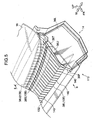
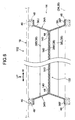
- Fig. 5 and Fig. 6 show an automobile cowl structure 112 according to a second exemplary embodiment of the present invention.
- Structural elements, members and the like of the second exemplary embodiment that are the same as in the first exemplary embodiment are assigned the same reference numerals and are not described in detail.
- a guide plate 138 that is different from the guide plate 38 according to the first exemplary embodiment is used.
- the overall shape of the guide plate 138 is similar to the guide plate 38 of the first exemplary embodiment.
- a plural number of furrows 140 are formed along the up-and-down direction, with a constant spacing in the vehicle width direction.
- the guide plate 138 differs from the first exemplary embodiment.
- Each of the creases 140 continues past the supplementary plate 38S partway between a top edge 138T and a bottom edge 138B of the guide plate 138.
- the furrows 140 are formed in trench shapes in the upper face side of the guide plate 138.
- the guide plate 138 is weakened at portions by these furrows 140. Therefore, the guide plate 138 according to the second exemplary embodiment is deformed more easily by a load from the upper side than the guide plate 38 according to the first exemplary embodiment in which the furrows 140 are not formed.
- the furrows 140 are an example of the weakened portion of the present invention.
- a deformation can be mentioned in which, for example, the guide plate 138 is deformed to inflect at regions of the furrows 140, this inflecting deformation occurs at a plural number of the furrows 140, and the guide plate 138 as a whole goes into a curved shape.
- Furrows 142 are formed at the rear face of the guide plate 138, at positions of the inflected portions 42A and 42B. Because of these furrows 142, if an impact acts from the upper side, the guide plate 138 is easily changed to a flat shape overall (see Fig. 8A and Fig. 8B ) by the impact.
- the guide plate 138 maintains the state into which the inflected portions 42A and 42B were inflected beforehand, being in a shape in which the upper portion 38U and the lower portion 38L are inflected with respect to the middle portion 38M. Therefore, in this guide plate 138, stiffness is higher than in a guide plate that is formed in a flat shape overall, and there is no unintended deformation at the furrows 140.
- the inflections of the inflected portions 42A and 42B are removed at a length direction middle region of the guide plate 138, as shown in Fig. 8A and Fig. 8B , and the guide plate 138 changes to an overall flat shape.
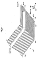
- the guide plate 138 When the guide plate 138 has changed to the flat shape, because the furrows 140 are formed in the guide plate 138, the guide plate 138 is deformed by the load, for example, as shown in Fig. 9 . Alternatively, as mentioned above, the guide plate 138 may deform into a curved shape overall.
- this load may be effectively absorbed by deformation of the guide plate 138.
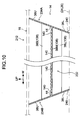
- Fig. 10 shows an automobile cowl structure 212 according to a third exemplary embodiment of the present invention.
- Structural elements, members and the like of the third exemplary embodiment that are the same as in the first exemplary embodiment or the second exemplary embodiment are assigned the same reference numerals and are not described in detail.
- the guide plate 138 in which the furrows 140 are formed is used, the same as in the screen member structural body 132 according to the second exemplary embodiment.
- the structures of screen plates 234A and 234B at the two vehicle width direction ends of the guide plate 138 are different.
- the screen plate 234A according to the third exemplary embodiment is formed in a flat shape overall, with the upper inflected portion 36U and the lower inflected portion 36L being inflected in the same direction.
- the screen plate 234B is also formed in a flat shape overall, with the upper inflected portion 36U and the lower inflected portion 36L being inflected in the same direction.
- the screen plate 234A and the screen plate 234B are inflected in directions such that the upper sides thereof are further apart in the vehicle width direction (the lower sides are closer together in the vehicle width direction).
- Positioning ribs 240 are formed at one or both of the cowl inner 24 and the cowl lower 26.
- the positioning ribs 240 touch against the screen plates 234A and 234B and position the screen member structural body 232 in the vehicle width direction.
- the positioning ribs 240 are formed at positions that touch against the screen plates 234A and 234B from vehicle width direction outer sides thereof.
- the screen member structural body 232 when the screen member structural body 232 is disposed in the cowl portion 14, the screen member structural body 232 is disposed such that the respective screen plates 234A and 234B are disposed at the vehicle width direction inner sides of the corresponding positioning ribs 240. Therefore, the screen member structural body 232 may be disposed at a predetermined position simply by being placed in the cowl portion 14.
- the screen plates 234A and 234B according to the third exemplary embodiment are not inflected and the trough portions 36T are not formed at the boundaries 44, as shown in Fig. 11 , the screen plates 234A and 234B do not buckle even when a load acts on the screen plate 234A (or the screen plate 234B) from the upper side.
- the screen plates 234A and 234B absorb an impact (energy) by tipping about the boundaries 44 in directions such that the upper sides thereof move away from one another.
- the positioning ribs 240 position the screen member structural body 232 by touching against the respective lower end portions of the screen plates 234A and 234B at the vehicle width direction outer sides relative to the screen plates 234A and 234B. Therefore, if the screen plates 234A and 234B are tipped over by an impact from the upper side, the positioning ribs 240 do not obstruct this tipping.
- Fig. 12 shows an automobile cowl structure 312 according to a fourth exemplary embodiment of the present invention.
- Structural elements, members and the like of the fourth exemplary embodiment that are the same as in the first to third exemplary embodiments are assigned the same reference numerals and are not described in detail.
- directions of inclination of screen plates 334A and 334B are different from in the third exemplary embodiment. That is, the screen plate 334A and screen plate 334B are inclined such that the upper sides thereof are closer together in the vehicle width direction and the lower sides thereof are further apart in the vehicle width direction.
- Positioning ribs 340 according to the fourth exemplary embodiment are formed at positions that touch against the screen plates 334A and 334B from the vehicle width direction inner sides thereof.
- the furrows 140 at which the guide plate 138 is reduced in plate thickness in linear shapes are mentioned as an example of the weakened portion of the present invention.
- the weakened portion is not limited to the furrows 140 (reduced plate thickness portions at which the guide plate 138 is locally made thinner), provided the guide plate 138 can be weakened and the stiffness lowered at portions thereof.
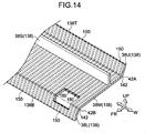
- a structure is possible in which a plural number of penetrating holes 150 that penetrate from the top edge 138T to the bottom edge 138B of the guide plate 138 are formed with a constant spacing in the vehicle width direction.
- the guide plate 38 is locally weakened at portions at which the penetrating holes 150 are formed, an impact (energy) from the upper side may be absorbed by deformation more effectively than in a guide plate in which these penetrating holes 150 are not formed.
- the weakened portion may be provided by a simple structure.
- the number of weakened portions is not necessarily a plural number. For example, even if a weakened portion is formed at only one location of the guide plate 138, an impact (energy) may be absorbed by this weakened portion being deformed by a load from the upper side.
- the number of screen plates may be three or more. In a structure in which three or more screen plates are provided, it is sufficient that the respective screen plates be joined by a guide plate and integrated as a whole.
- a screen plate includes inclined portions (an upper inclined portion and a lower inclined portion)
- it is not necessary for the screen plate to be wholly inclined and structures are possible in which a portion of the screen plate is in line with the vertical direction.
- a structure is possible in which a predetermined range at the upper side and the lower side of the boundary 44 is provided standing in the vertical direction, and portions at the upper side and the lower side of this vertical portion are inclined.
- the low-stiffness portion of the present invention may be provided at the vertical portion or at a boundary between the vertical portion and an inclined portion.
Landscapes
- Engineering & Computer Science (AREA)
- Mechanical Engineering (AREA)
- Chemical & Material Sciences (AREA)
- Combustion & Propulsion (AREA)
- Transportation (AREA)
- Physics & Mathematics (AREA)
- Thermal Sciences (AREA)
- Body Structure For Vehicles (AREA)
Claims (6)
- Stirnwandstruktur (12; 112; 212; 132) für ein Automobil, aufweisend:eine Führungsplatte (38; 138), die sich in einem Stirnwandabschnitt (14) eines Fahrzeugs befindet und zumindest eine Flüssigkeit, die in den Stirnwandabschnitt (14) gelangt, durch ein Stirnwandgitter (18) in Richtung einer Vorderseite des Fahrzeugs führt; undeine Mehrzahl an Siebblechen (34A, 34B; 234A, 234B; 334A, 334B), die im Inneren des Stirnwandabschnitts (14) stehend angeordnet sind und die die Bewegung von Luft, die von einem Motorraum (40) hereinströmt, in einer Breitenrichtung des Fahrzeugs behindern, und die durch die Führungsplatte (38; 138) zusammengefügt sind,dadurch gekennzeichnet, dass zumindest eines von einem oberen Seitenabschnitt oder einem unteren Seitenabschnitt von jedem Siebblech (34A, 34B; 234A, 234B; 334A, 334B) ein geneigter Abschnitt (36U, 36L) relativ zu einer Grenze (44) mit der Führungsplatte (38; 138) ist, der von einer vertikalen Richtung aus geneigt ist.
- Stirnwandstruktur (12; 112; 212; 132) für ein Automobil nach Anspruch 1, wobei der geneigte Abschnitt Folgendes beinhaltet:einen oberen geneigten Abschnitt (36U) an der relativ zu einem Bereich der Grenze oberen Seite; undeinen unteren geneigten Abschnitt (36L) an der relativ zu dem Bereich der Grenze unteren Seite, wobei der untere geneigte Abschnitt (36L) von dem oberen geneigten Abschnitt (36U) in einer unterschiedlichen Richtung geneigt ist,und wobei sich ein Abschnitt mit niedriger Steifigkeit (36T), bei dem das Siebblech lokal eine niedrige Steifigkeit aufweist, zwischen dem oberen geneigten Abschnitt (36U) und dem unteren geneigten Abschnitt (36L) befindet.
- Stirnwandstruktur (12; 112; 212; 132) für ein Automobil nach Anspruch 1, wobei jedes von der Mehrzahl an Siebblechen (34A, 34B, 234A, 234B; 334A, 334B) flach ist und so angeordnet ist, dass es im Verhältnis zu der vertikalen Richtung geneigt ist.
- Stirnwandstruktur (12; 112; 212; 132) für ein Automobil nach einem der Ansprüche 1 bis 3, wobei die Führungsplatte (38; 138) einen geschwächten Abschnitt (140; 150) beinhaltet, an dem eine Biegestärke der Führungsplatte (38; 138) im Verhältnis zu einer Belastung von einer Fahrzeugaußenseite reduziert ist.
- Stirnwandstruktur (12; 112; 212; 132) für ein Automobil nach Anspruch 4, wobei der geschwächte Abschnitt (140) ein Abschnitt mit reduzierter Plattendicke ist, bei dem die Dicke der Führungsplatte (38; 138) lokal entlang einer Oben-und-Unten-Richtung verringert ist.
- Stirnwandstruktur (12; 112; 212; 132) für ein Automobil nach Anspruch 5, wobei der geschwächte Abschnitt (150) mehrfach vorhanden ist und die geschwächten Abschnitte (150) in einer Breitenrichtung des Fahrzeugs voneinander beabstandet sind.
Applications Claiming Priority (1)
| Application Number | Priority Date | Filing Date | Title |
|---|---|---|---|
| PCT/JP2011/054147 WO2012114496A1 (ja) | 2011-02-24 | 2011-02-24 | 自動車用カウル部構造 |
Publications (4)
| Publication Number | Publication Date |
|---|---|
| EP2679471A1 EP2679471A1 (de) | 2014-01-01 |
| EP2679471A8 EP2679471A8 (de) | 2014-02-19 |
| EP2679471A4 EP2679471A4 (de) | 2014-09-24 |
| EP2679471B1 true EP2679471B1 (de) | 2015-10-21 |
Family
ID=46720313
Family Applications (1)
| Application Number | Title | Priority Date | Filing Date |
|---|---|---|---|
| EP11859223.7A Not-in-force EP2679471B1 (de) | 2011-02-24 | 2011-02-24 | Wasserkastenstruktur eines kraftfahrzeuges |
Country Status (5)
| Country | Link |
|---|---|
| US (1) | US8882182B2 (de) |
| EP (1) | EP2679471B1 (de) |
| JP (1) | JP5459440B2 (de) |
| CN (1) | CN103347774B (de) |
| WO (1) | WO2012114496A1 (de) |
Families Citing this family (12)
| Publication number | Priority date | Publication date | Assignee | Title |
|---|---|---|---|---|
| JP5711942B2 (ja) * | 2010-11-19 | 2015-05-07 | 日本プラスト株式会社 | カウルトップカバー |
| JP5459440B2 (ja) * | 2011-02-24 | 2014-04-02 | トヨタ自動車株式会社 | 自動車用カウル部構造 |
| EP2730486B1 (de) * | 2011-07-04 | 2016-04-27 | Honda Motor Co., Ltd. | Struktur für die frontpartie eines fahrzeugs |
| DE102012023655A1 (de) * | 2012-11-28 | 2014-05-28 | GM Global Technology Operations LLC (n. d. Gesetzen des Staates Delaware) | Kraftfahrzeug-Muldenmodul mit Dichtung |
| US9981697B2 (en) * | 2014-04-03 | 2018-05-29 | Toyota Jidosha Kabushiki Kaisha | Cowl structure for a vehicle |
| JP6494217B2 (ja) * | 2014-08-28 | 2019-04-03 | ダイハツ工業株式会社 | 自動車のカウル部構造 |
| WO2016095995A1 (en) * | 2014-12-17 | 2016-06-23 | Toyota Motor Europe Nv/Sa | Deflector for reduced head injury criterion |
| JP6636720B2 (ja) | 2015-05-18 | 2020-01-29 | トヨタ自動車株式会社 | カウル構造 |
| JP6565889B2 (ja) * | 2016-12-19 | 2019-08-28 | トヨタ自動車株式会社 | 車両前部構造 |
| JP7198798B2 (ja) * | 2020-11-13 | 2023-01-04 | 本田技研工業株式会社 | 車両前部構造 |
| JP7491474B2 (ja) | 2021-07-20 | 2024-05-28 | トヨタ車体株式会社 | 車両のカウルルーバ |
| JP7776360B2 (ja) * | 2022-03-21 | 2025-11-26 | 株式会社Subaru | 車両のカウル構造 |
Family Cites Families (28)
| Publication number | Priority date | Publication date | Assignee | Title |
|---|---|---|---|---|
| DE69009002T2 (de) * | 1989-10-31 | 1994-09-01 | Mazda Motor | Fahrzeugvorderwagenaufbau. |
| JP2564688B2 (ja) * | 1990-06-01 | 1996-12-18 | 日産自動車株式会社 | 車体構造 |
| JP2528541B2 (ja) | 1990-07-25 | 1996-08-28 | 矢崎総業株式会社 | 吸収ヒ―トポンプ |
| JPH0484082U (de) * | 1990-11-30 | 1992-07-22 | ||
| JPH0537657A (ja) | 1991-07-29 | 1993-02-12 | Nippon Telegr & Teleph Corp <Ntt> | オペレータ多重利用方式 |
| JPH0537657U (ja) * | 1991-10-30 | 1993-05-21 | マツダ株式会社 | 自動車の前部車体構造 |
| JP3173148B2 (ja) * | 1992-06-18 | 2001-06-04 | 株式会社豊田自動織機製作所 | 自動車のカウル構造 |
| US6565148B1 (en) * | 1999-09-10 | 2003-05-20 | Toyoda Gosei Co., Ltd. | Assembly structure for cowl louver |
| JP3610959B2 (ja) * | 2002-03-20 | 2005-01-19 | 日産自動車株式会社 | 車両のカウル構造 |
| JP4104392B2 (ja) | 2002-07-25 | 2008-06-18 | 日野自動車株式会社 | 外気導入部の水入り防止構造 |
| US6868928B2 (en) * | 2002-11-26 | 2005-03-22 | International Truck Intellectual Property Company, Llc | Fluid center |
| JP4476118B2 (ja) * | 2004-07-27 | 2010-06-09 | 日本プラスト株式会社 | カウルトップカバー |
| JP4685595B2 (ja) | 2005-11-02 | 2011-05-18 | 株式会社豊田自動織機 | 車両のカウルダクト |
| DE602008000247D1 (de) * | 2007-09-10 | 2009-12-10 | Honda Motor Co Ltd | Vorderteilkonstruktion eines Fahrzeuges |
| JP2009067329A (ja) | 2007-09-14 | 2009-04-02 | Kanto Auto Works Ltd | カウル構造 |
| JP5119915B2 (ja) * | 2007-12-28 | 2013-01-16 | マツダ株式会社 | 車両のカウルグリル構造 |
| JP5347313B2 (ja) * | 2008-04-18 | 2013-11-20 | スズキ株式会社 | 車両のカウル部構造 |
| JP5203815B2 (ja) | 2008-06-30 | 2013-06-05 | ダイハツ工業株式会社 | 車両用カウルルーバの衝撃力吸収構造 |
| JP2010168036A (ja) * | 2008-12-26 | 2010-08-05 | Nitto Denko Corp | 遮蔽板およびその遮蔽板を備える車両構造 |
| JP5394759B2 (ja) * | 2009-01-23 | 2014-01-22 | 日本プラスト株式会社 | カウルトップカバーの取付構造 |
| JP5303737B2 (ja) * | 2009-06-25 | 2013-10-02 | トヨタ車体株式会社 | 自動車におけるカウルルーバ支持構造 |
| GB2486844B (en) * | 2009-09-01 | 2012-10-10 | Nihon Plast Co Ltd | A cowl-top cover |
| JP5507408B2 (ja) * | 2010-10-18 | 2014-05-28 | 小島プレス工業株式会社 | カウルルーバー用シール構造 |
| JP5711942B2 (ja) * | 2010-11-19 | 2015-05-07 | 日本プラスト株式会社 | カウルトップカバー |
| JP5652216B2 (ja) * | 2011-01-18 | 2015-01-14 | スズキ株式会社 | 車両のカウル部構造 |
| JP5459440B2 (ja) * | 2011-02-24 | 2014-04-02 | トヨタ自動車株式会社 | 自動車用カウル部構造 |
| US8567851B2 (en) * | 2011-09-23 | 2013-10-29 | Nissan North America, Inc. | Vehicle cowl cover |
| DE102012008934A1 (de) * | 2012-05-08 | 2013-11-14 | GM Global Technology Operations LLC (n.d. Ges. d. Staates Delaware) | Kraftfahrzeug mit Wasserkasten |
-
2011
- 2011-02-24 JP JP2013500786A patent/JP5459440B2/ja not_active Expired - Fee Related
- 2011-02-24 US US13/983,147 patent/US8882182B2/en not_active Expired - Fee Related
- 2011-02-24 WO PCT/JP2011/054147 patent/WO2012114496A1/ja not_active Ceased
- 2011-02-24 EP EP11859223.7A patent/EP2679471B1/de not_active Not-in-force
- 2011-02-24 CN CN201180067386.2A patent/CN103347774B/zh not_active Expired - Fee Related
Also Published As
| Publication number | Publication date |
|---|---|
| EP2679471A8 (de) | 2014-02-19 |
| CN103347774A (zh) | 2013-10-09 |
| JP5459440B2 (ja) | 2014-04-02 |
| EP2679471A4 (de) | 2014-09-24 |
| EP2679471A1 (de) | 2014-01-01 |
| US8882182B2 (en) | 2014-11-11 |
| WO2012114496A1 (ja) | 2012-08-30 |
| CN103347774B (zh) | 2015-03-25 |
| US20130320712A1 (en) | 2013-12-05 |
| JPWO2012114496A1 (ja) | 2014-07-07 |
Similar Documents
| Publication | Publication Date | Title |
|---|---|---|
| EP2679471B1 (de) | Wasserkastenstruktur eines kraftfahrzeuges | |
| US9126634B2 (en) | Structure for front portion of vehicle | |
| CN111376988B (zh) | 前围上盖板结构 | |
| US20060087155A1 (en) | Cowl top cover | |
| US10350978B2 (en) | Water drain structure of sunroof in vehicle | |
| US7883141B2 (en) | Vehicle body structure | |
| CN108202768A (zh) | 车辆前部结构 | |
| CN102452365A (zh) | 车颈通风件密封结构 | |
| JP6143530B2 (ja) | カウルトップカバー | |
| JP5719422B2 (ja) | 車両のカウルトップ構造 | |
| JP4291722B2 (ja) | カウルトップカバー | |
| EP2657088B1 (de) | Stossfängermodul | |
| JP4826958B2 (ja) | 自動車のカウルボックス構造 | |
| JP2022131150A (ja) | 車両用カウル構造 | |
| JP7342685B2 (ja) | 車両の荷室構造 | |
| JP6056589B2 (ja) | 車両のフロントデッキ構造 | |
| JP2009286322A (ja) | カウルルーバ | |
| JP7491474B2 (ja) | 車両のカウルルーバ | |
| JP2009045996A (ja) | 四輪車両のカウル構造 | |
| JP6312249B2 (ja) | カウルカバー装置 | |
| JP2015214304A (ja) | 車両前部構造 | |
| JP5717417B2 (ja) | カウルトップカバー | |
| JP6468477B2 (ja) | 車両のデッキガーニッシュ構造 | |
| JP5237749B2 (ja) | 車両用カウルルーバの衝撃力吸収構造 | |
| JP7158326B2 (ja) | 車両用スポイラー |
Legal Events
| Date | Code | Title | Description |
|---|---|---|---|
| PUAI | Public reference made under article 153(3) epc to a published international application that has entered the european phase |
Free format text: ORIGINAL CODE: 0009012 |
|
| 17P | Request for examination filed |
Effective date: 20130812 |
|
| AK | Designated contracting states |
Kind code of ref document: A1 Designated state(s): AL AT BE BG CH CY CZ DE DK EE ES FI FR GB GR HR HU IE IS IT LI LT LU LV MC MK MT NL NO PL PT RO RS SE SI SK SM TR |
|
| RIN1 | Information on inventor provided before grant (corrected) |
Inventor name: NOMURA, HIROKI Inventor name: MUROFUSHI, SHINICHIRO Inventor name: YOSHIZAWA, SHINSUKE |
|
| DAX | Request for extension of the european patent (deleted) | ||
| A4 | Supplementary search report drawn up and despatched |
Effective date: 20140825 |
|
| RIC1 | Information provided on ipc code assigned before grant |
Ipc: B62D 25/08 20060101AFI20140819BHEP |
|
| GRAP | Despatch of communication of intention to grant a patent |
Free format text: ORIGINAL CODE: EPIDOSNIGR1 |
|
| INTG | Intention to grant announced |
Effective date: 20150508 |
|
| GRAS | Grant fee paid |
Free format text: ORIGINAL CODE: EPIDOSNIGR3 |
|
| GRAA | (expected) grant |
Free format text: ORIGINAL CODE: 0009210 |
|
| AK | Designated contracting states |
Kind code of ref document: B1 Designated state(s): AL AT BE BG CH CY CZ DE DK EE ES FI FR GB GR HR HU IE IS IT LI LT LU LV MC MK MT NL NO PL PT RO RS SE SI SK SM TR |
|
| REG | Reference to a national code |
Ref country code: GB Ref legal event code: FG4D Ref country code: NL Ref legal event code: MP Effective date: 20151021 |
|
| REG | Reference to a national code |
Ref country code: CH Ref legal event code: EP |
|
| REG | Reference to a national code |
Ref country code: AT Ref legal event code: REF Ref document number: 756407 Country of ref document: AT Kind code of ref document: T Effective date: 20151115 |
|
| REG | Reference to a national code |
Ref country code: IE Ref legal event code: FG4D |
|
| REG | Reference to a national code |
Ref country code: DE Ref legal event code: R096 Ref document number: 602011020916 Country of ref document: DE |
|
| REG | Reference to a national code |
Ref country code: LT Ref legal event code: MG4D |
|
| REG | Reference to a national code |
Ref country code: AT Ref legal event code: MK05 Ref document number: 756407 Country of ref document: AT Kind code of ref document: T Effective date: 20151021 |
|
| PG25 | Lapsed in a contracting state [announced via postgrant information from national office to epo] |
Ref country code: LT Free format text: LAPSE BECAUSE OF FAILURE TO SUBMIT A TRANSLATION OF THE DESCRIPTION OR TO PAY THE FEE WITHIN THE PRESCRIBED TIME-LIMIT Effective date: 20151021 Ref country code: IT Free format text: LAPSE BECAUSE OF FAILURE TO SUBMIT A TRANSLATION OF THE DESCRIPTION OR TO PAY THE FEE WITHIN THE PRESCRIBED TIME-LIMIT Effective date: 20151021 Ref country code: IS Free format text: LAPSE BECAUSE OF FAILURE TO SUBMIT A TRANSLATION OF THE DESCRIPTION OR TO PAY THE FEE WITHIN THE PRESCRIBED TIME-LIMIT Effective date: 20160221 Ref country code: HR Free format text: LAPSE BECAUSE OF FAILURE TO SUBMIT A TRANSLATION OF THE DESCRIPTION OR TO PAY THE FEE WITHIN THE PRESCRIBED TIME-LIMIT Effective date: 20151021 Ref country code: ES Free format text: LAPSE BECAUSE OF FAILURE TO SUBMIT A TRANSLATION OF THE DESCRIPTION OR TO PAY THE FEE WITHIN THE PRESCRIBED TIME-LIMIT Effective date: 20151021 Ref country code: NL Free format text: LAPSE BECAUSE OF FAILURE TO SUBMIT A TRANSLATION OF THE DESCRIPTION OR TO PAY THE FEE WITHIN THE PRESCRIBED TIME-LIMIT Effective date: 20151021 Ref country code: NO Free format text: LAPSE BECAUSE OF FAILURE TO SUBMIT A TRANSLATION OF THE DESCRIPTION OR TO PAY THE FEE WITHIN THE PRESCRIBED TIME-LIMIT Effective date: 20160121 |
|
| PG25 | Lapsed in a contracting state [announced via postgrant information from national office to epo] |
Ref country code: GR Free format text: LAPSE BECAUSE OF FAILURE TO SUBMIT A TRANSLATION OF THE DESCRIPTION OR TO PAY THE FEE WITHIN THE PRESCRIBED TIME-LIMIT Effective date: 20160122 Ref country code: PL Free format text: LAPSE BECAUSE OF FAILURE TO SUBMIT A TRANSLATION OF THE DESCRIPTION OR TO PAY THE FEE WITHIN THE PRESCRIBED TIME-LIMIT Effective date: 20151021 Ref country code: LV Free format text: LAPSE BECAUSE OF FAILURE TO SUBMIT A TRANSLATION OF THE DESCRIPTION OR TO PAY THE FEE WITHIN THE PRESCRIBED TIME-LIMIT Effective date: 20151021 Ref country code: RS Free format text: LAPSE BECAUSE OF FAILURE TO SUBMIT A TRANSLATION OF THE DESCRIPTION OR TO PAY THE FEE WITHIN THE PRESCRIBED TIME-LIMIT Effective date: 20151021 Ref country code: PT Free format text: LAPSE BECAUSE OF FAILURE TO SUBMIT A TRANSLATION OF THE DESCRIPTION OR TO PAY THE FEE WITHIN THE PRESCRIBED TIME-LIMIT Effective date: 20160222 Ref country code: FI Free format text: LAPSE BECAUSE OF FAILURE TO SUBMIT A TRANSLATION OF THE DESCRIPTION OR TO PAY THE FEE WITHIN THE PRESCRIBED TIME-LIMIT Effective date: 20151021 Ref country code: AT Free format text: LAPSE BECAUSE OF FAILURE TO SUBMIT A TRANSLATION OF THE DESCRIPTION OR TO PAY THE FEE WITHIN THE PRESCRIBED TIME-LIMIT Effective date: 20151021 Ref country code: SE Free format text: LAPSE BECAUSE OF FAILURE TO SUBMIT A TRANSLATION OF THE DESCRIPTION OR TO PAY THE FEE WITHIN THE PRESCRIBED TIME-LIMIT Effective date: 20151021 Ref country code: BE Free format text: LAPSE BECAUSE OF NON-PAYMENT OF DUE FEES Effective date: 20160229 |
|
| REG | Reference to a national code |
Ref country code: DE Ref legal event code: R097 Ref document number: 602011020916 Country of ref document: DE |
|
| PG25 | Lapsed in a contracting state [announced via postgrant information from national office to epo] |
Ref country code: CZ Free format text: LAPSE BECAUSE OF FAILURE TO SUBMIT A TRANSLATION OF THE DESCRIPTION OR TO PAY THE FEE WITHIN THE PRESCRIBED TIME-LIMIT Effective date: 20151021 |
|
| PLBE | No opposition filed within time limit |
Free format text: ORIGINAL CODE: 0009261 |
|
| STAA | Information on the status of an ep patent application or granted ep patent |
Free format text: STATUS: NO OPPOSITION FILED WITHIN TIME LIMIT |
|
| PG25 | Lapsed in a contracting state [announced via postgrant information from national office to epo] |
Ref country code: DK Free format text: LAPSE BECAUSE OF FAILURE TO SUBMIT A TRANSLATION OF THE DESCRIPTION OR TO PAY THE FEE WITHIN THE PRESCRIBED TIME-LIMIT Effective date: 20151021 Ref country code: RO Free format text: LAPSE BECAUSE OF FAILURE TO SUBMIT A TRANSLATION OF THE DESCRIPTION OR TO PAY THE FEE WITHIN THE PRESCRIBED TIME-LIMIT Effective date: 20151021 Ref country code: EE Free format text: LAPSE BECAUSE OF FAILURE TO SUBMIT A TRANSLATION OF THE DESCRIPTION OR TO PAY THE FEE WITHIN THE PRESCRIBED TIME-LIMIT Effective date: 20151021 Ref country code: SK Free format text: LAPSE BECAUSE OF FAILURE TO SUBMIT A TRANSLATION OF THE DESCRIPTION OR TO PAY THE FEE WITHIN THE PRESCRIBED TIME-LIMIT Effective date: 20151021 Ref country code: SM Free format text: LAPSE BECAUSE OF FAILURE TO SUBMIT A TRANSLATION OF THE DESCRIPTION OR TO PAY THE FEE WITHIN THE PRESCRIBED TIME-LIMIT Effective date: 20151021 |
|
| 26N | No opposition filed |
Effective date: 20160722 |
|
| PG25 | Lapsed in a contracting state [announced via postgrant information from national office to epo] |
Ref country code: MC Free format text: LAPSE BECAUSE OF FAILURE TO SUBMIT A TRANSLATION OF THE DESCRIPTION OR TO PAY THE FEE WITHIN THE PRESCRIBED TIME-LIMIT Effective date: 20151021 Ref country code: LU Free format text: LAPSE BECAUSE OF FAILURE TO SUBMIT A TRANSLATION OF THE DESCRIPTION OR TO PAY THE FEE WITHIN THE PRESCRIBED TIME-LIMIT Effective date: 20160224 |
|
| REG | Reference to a national code |
Ref country code: CH Ref legal event code: PL |
|
| GBPC | Gb: european patent ceased through non-payment of renewal fee |
Effective date: 20160224 |
|
| PG25 | Lapsed in a contracting state [announced via postgrant information from national office to epo] |
Ref country code: CH Free format text: LAPSE BECAUSE OF NON-PAYMENT OF DUE FEES Effective date: 20160229 Ref country code: LI Free format text: LAPSE BECAUSE OF NON-PAYMENT OF DUE FEES Effective date: 20160229 |
|
| REG | Reference to a national code |
Ref country code: DE Ref legal event code: R084 Ref document number: 602011020916 Country of ref document: DE |
|
| REG | Reference to a national code |
Ref country code: FR Ref legal event code: ST Effective date: 20161028 |
|
| PG25 | Lapsed in a contracting state [announced via postgrant information from national office to epo] |
Ref country code: SI Free format text: LAPSE BECAUSE OF FAILURE TO SUBMIT A TRANSLATION OF THE DESCRIPTION OR TO PAY THE FEE WITHIN THE PRESCRIBED TIME-LIMIT Effective date: 20151021 |
|
| REG | Reference to a national code |
Ref country code: IE Ref legal event code: MM4A |
|
| PG25 | Lapsed in a contracting state [announced via postgrant information from national office to epo] |
Ref country code: BE Free format text: LAPSE BECAUSE OF FAILURE TO SUBMIT A TRANSLATION OF THE DESCRIPTION OR TO PAY THE FEE WITHIN THE PRESCRIBED TIME-LIMIT Effective date: 20151021 |
|
| PG25 | Lapsed in a contracting state [announced via postgrant information from national office to epo] |
Ref country code: GB Free format text: LAPSE BECAUSE OF NON-PAYMENT OF DUE FEES Effective date: 20160224 Ref country code: FR Free format text: LAPSE BECAUSE OF NON-PAYMENT OF DUE FEES Effective date: 20160229 Ref country code: IE Free format text: LAPSE BECAUSE OF NON-PAYMENT OF DUE FEES Effective date: 20160224 |
|
| PG25 | Lapsed in a contracting state [announced via postgrant information from national office to epo] |
Ref country code: MT Free format text: LAPSE BECAUSE OF FAILURE TO SUBMIT A TRANSLATION OF THE DESCRIPTION OR TO PAY THE FEE WITHIN THE PRESCRIBED TIME-LIMIT Effective date: 20151021 |
|
| PG25 | Lapsed in a contracting state [announced via postgrant information from national office to epo] |
Ref country code: CY Free format text: LAPSE BECAUSE OF FAILURE TO SUBMIT A TRANSLATION OF THE DESCRIPTION OR TO PAY THE FEE WITHIN THE PRESCRIBED TIME-LIMIT Effective date: 20151021 Ref country code: HU Free format text: LAPSE BECAUSE OF FAILURE TO SUBMIT A TRANSLATION OF THE DESCRIPTION OR TO PAY THE FEE WITHIN THE PRESCRIBED TIME-LIMIT; INVALID AB INITIO Effective date: 20110224 |
|
| PG25 | Lapsed in a contracting state [announced via postgrant information from national office to epo] |
Ref country code: TR Free format text: LAPSE BECAUSE OF FAILURE TO SUBMIT A TRANSLATION OF THE DESCRIPTION OR TO PAY THE FEE WITHIN THE PRESCRIBED TIME-LIMIT Effective date: 20151021 Ref country code: MK Free format text: LAPSE BECAUSE OF FAILURE TO SUBMIT A TRANSLATION OF THE DESCRIPTION OR TO PAY THE FEE WITHIN THE PRESCRIBED TIME-LIMIT Effective date: 20151021 Ref country code: MT Free format text: LAPSE BECAUSE OF FAILURE TO SUBMIT A TRANSLATION OF THE DESCRIPTION OR TO PAY THE FEE WITHIN THE PRESCRIBED TIME-LIMIT Effective date: 20160229 |
|
| PG25 | Lapsed in a contracting state [announced via postgrant information from national office to epo] |
Ref country code: BG Free format text: LAPSE BECAUSE OF FAILURE TO SUBMIT A TRANSLATION OF THE DESCRIPTION OR TO PAY THE FEE WITHIN THE PRESCRIBED TIME-LIMIT Effective date: 20151021 |
|
| PG25 | Lapsed in a contracting state [announced via postgrant information from national office to epo] |
Ref country code: AL Free format text: LAPSE BECAUSE OF FAILURE TO SUBMIT A TRANSLATION OF THE DESCRIPTION OR TO PAY THE FEE WITHIN THE PRESCRIBED TIME-LIMIT Effective date: 20151021 |
|
| PGFP | Annual fee paid to national office [announced via postgrant information from national office to epo] |
Ref country code: DE Payment date: 20211230 Year of fee payment: 12 |
|
| P01 | Opt-out of the competence of the unified patent court (upc) registered |
Effective date: 20230427 |
|
| REG | Reference to a national code |
Ref country code: DE Ref legal event code: R119 Ref document number: 602011020916 Country of ref document: DE |
|
| PG25 | Lapsed in a contracting state [announced via postgrant information from national office to epo] |
Ref country code: DE Free format text: LAPSE BECAUSE OF NON-PAYMENT OF DUE FEES Effective date: 20230901 |