EP2679509A1 - Réceptacle d'emballage et confiserie dans réceptacle d'emballage - Google Patents
Réceptacle d'emballage et confiserie dans réceptacle d'emballage Download PDFInfo
- Publication number
- EP2679509A1 EP2679509A1 EP12749600.8A EP12749600A EP2679509A1 EP 2679509 A1 EP2679509 A1 EP 2679509A1 EP 12749600 A EP12749600 A EP 12749600A EP 2679509 A1 EP2679509 A1 EP 2679509A1
- Authority
- EP
- European Patent Office
- Prior art keywords
- chamber
- packaging container
- wall
- rear chamber
- chewing gum
- Prior art date
- Legal status (The legal status is an assumption and is not a legal conclusion. Google has not performed a legal analysis and makes no representation as to the accuracy of the status listed.)
- Withdrawn
Links
Images






Classifications
-
- B—PERFORMING OPERATIONS; TRANSPORTING
- B65—CONVEYING; PACKING; STORING; HANDLING THIN OR FILAMENTARY MATERIAL
- B65D—CONTAINERS FOR STORAGE OR TRANSPORT OF ARTICLES OR MATERIALS, e.g. BAGS, BARRELS, BOTTLES, BOXES, CANS, CARTONS, CRATES, DRUMS, JARS, TANKS, HOPPERS, FORWARDING CONTAINERS; ACCESSORIES, CLOSURES, OR FITTINGS THEREFOR; PACKAGING ELEMENTS; PACKAGES
- B65D77/00—Packages formed by enclosing articles or materials in preformed containers, e.g. boxes, cartons, sacks or bags
- B65D77/02—Wrapped articles enclosed in rigid or semi-rigid containers
-
- B—PERFORMING OPERATIONS; TRANSPORTING
- B65—CONVEYING; PACKING; STORING; HANDLING THIN OR FILAMENTARY MATERIAL
- B65D—CONTAINERS FOR STORAGE OR TRANSPORT OF ARTICLES OR MATERIALS, e.g. BAGS, BARRELS, BOTTLES, BOXES, CANS, CARTONS, CRATES, DRUMS, JARS, TANKS, HOPPERS, FORWARDING CONTAINERS; ACCESSORIES, CLOSURES, OR FITTINGS THEREFOR; PACKAGING ELEMENTS; PACKAGES
- B65D5/00—Rigid or semi-rigid containers of polygonal cross-section, e.g. boxes, cartons or trays, formed by folding or erecting one or more blanks made of paper
- B65D5/18—Rigid or semi-rigid containers of polygonal cross-section, e.g. boxes, cartons or trays, formed by folding or erecting one or more blanks made of paper by folding a single blank to U-shape to form the base of the container and opposite sides of the body portion, the remaining sides being formed primarily by extensions of one or more of these opposite sides, e.g. flaps hinged thereto
-
- B—PERFORMING OPERATIONS; TRANSPORTING
- B65—CONVEYING; PACKING; STORING; HANDLING THIN OR FILAMENTARY MATERIAL
- B65D—CONTAINERS FOR STORAGE OR TRANSPORT OF ARTICLES OR MATERIALS, e.g. BAGS, BARRELS, BOTTLES, BOXES, CANS, CARTONS, CRATES, DRUMS, JARS, TANKS, HOPPERS, FORWARDING CONTAINERS; ACCESSORIES, CLOSURES, OR FITTINGS THEREFOR; PACKAGING ELEMENTS; PACKAGES
- B65D5/00—Rigid or semi-rigid containers of polygonal cross-section, e.g. boxes, cartons or trays, formed by folding or erecting one or more blanks made of paper
- B65D5/32—Rigid or semi-rigid containers of polygonal cross-section, e.g. boxes, cartons or trays, formed by folding or erecting one or more blanks made of paper having bodies formed by folding and interconnecting two or more blanks
- B65D5/322—Rigid or semi-rigid containers of polygonal cross-section, e.g. boxes, cartons or trays, formed by folding or erecting one or more blanks made of paper having bodies formed by folding and interconnecting two or more blanks at least one container body part formed by folding a single blank to essentially U-shape with or without extensions which form openable lid elements
- B65D5/324—Rigid or semi-rigid containers of polygonal cross-section, e.g. boxes, cartons or trays, formed by folding or erecting one or more blanks made of paper having bodies formed by folding and interconnecting two or more blanks at least one container body part formed by folding a single blank to essentially U-shape with or without extensions which form openable lid elements at least two container body parts, each formed by folding a single blank to essentially U-shape
-
- B—PERFORMING OPERATIONS; TRANSPORTING
- B65—CONVEYING; PACKING; STORING; HANDLING THIN OR FILAMENTARY MATERIAL
- B65D—CONTAINERS FOR STORAGE OR TRANSPORT OF ARTICLES OR MATERIALS, e.g. BAGS, BARRELS, BOTTLES, BOXES, CANS, CARTONS, CRATES, DRUMS, JARS, TANKS, HOPPERS, FORWARDING CONTAINERS; ACCESSORIES, CLOSURES, OR FITTINGS THEREFOR; PACKAGING ELEMENTS; PACKAGES
- B65D5/00—Rigid or semi-rigid containers of polygonal cross-section, e.g. boxes, cartons or trays, formed by folding or erecting one or more blanks made of paper
- B65D5/32—Rigid or semi-rigid containers of polygonal cross-section, e.g. boxes, cartons or trays, formed by folding or erecting one or more blanks made of paper having bodies formed by folding and interconnecting two or more blanks
- B65D5/326—Rigid or semi-rigid containers of polygonal cross-section, e.g. boxes, cartons or trays, formed by folding or erecting one or more blanks made of paper having bodies formed by folding and interconnecting two or more blanks at least one container body part formed by folding a single blank to a permanently assembled tube
-
- B—PERFORMING OPERATIONS; TRANSPORTING
- B65—CONVEYING; PACKING; STORING; HANDLING THIN OR FILAMENTARY MATERIAL
- B65D—CONTAINERS FOR STORAGE OR TRANSPORT OF ARTICLES OR MATERIALS, e.g. BAGS, BARRELS, BOTTLES, BOXES, CANS, CARTONS, CRATES, DRUMS, JARS, TANKS, HOPPERS, FORWARDING CONTAINERS; ACCESSORIES, CLOSURES, OR FITTINGS THEREFOR; PACKAGING ELEMENTS; PACKAGES
- B65D5/00—Rigid or semi-rigid containers of polygonal cross-section, e.g. boxes, cartons or trays, formed by folding or erecting one or more blanks made of paper
- B65D5/38—Drawer-and-shell type containers
-
- B—PERFORMING OPERATIONS; TRANSPORTING
- B65—CONVEYING; PACKING; STORING; HANDLING THIN OR FILAMENTARY MATERIAL
- B65D—CONTAINERS FOR STORAGE OR TRANSPORT OF ARTICLES OR MATERIALS, e.g. BAGS, BARRELS, BOTTLES, BOXES, CANS, CARTONS, CRATES, DRUMS, JARS, TANKS, HOPPERS, FORWARDING CONTAINERS; ACCESSORIES, CLOSURES, OR FITTINGS THEREFOR; PACKAGING ELEMENTS; PACKAGES
- B65D5/00—Rigid or semi-rigid containers of polygonal cross-section, e.g. boxes, cartons or trays, formed by folding or erecting one or more blanks made of paper
- B65D5/42—Details of containers or of foldable or erectable container blanks
- B65D5/427—Individual packages joined together, e.g. by means of integral tabs
-
- B—PERFORMING OPERATIONS; TRANSPORTING
- B65—CONVEYING; PACKING; STORING; HANDLING THIN OR FILAMENTARY MATERIAL
- B65D—CONTAINERS FOR STORAGE OR TRANSPORT OF ARTICLES OR MATERIALS, e.g. BAGS, BARRELS, BOTTLES, BOXES, CANS, CARTONS, CRATES, DRUMS, JARS, TANKS, HOPPERS, FORWARDING CONTAINERS; ACCESSORIES, CLOSURES, OR FITTINGS THEREFOR; PACKAGING ELEMENTS; PACKAGES
- B65D5/00—Rigid or semi-rigid containers of polygonal cross-section, e.g. boxes, cartons or trays, formed by folding or erecting one or more blanks made of paper
- B65D5/42—Details of containers or of foldable or erectable container blanks
- B65D5/54—Lines of weakness to facilitate opening of container or dividing it into separate parts by cutting or tearing
- B65D5/5405—Lines of weakness to facilitate opening of container or dividing it into separate parts by cutting or tearing for opening containers formed by erecting a blank in tubular form
- B65D5/542—Lines of weakness to facilitate opening of container or dividing it into separate parts by cutting or tearing for opening containers formed by erecting a blank in tubular form the lines of weakness being provided in the container body
-
- B—PERFORMING OPERATIONS; TRANSPORTING
- B65—CONVEYING; PACKING; STORING; HANDLING THIN OR FILAMENTARY MATERIAL
- B65D—CONTAINERS FOR STORAGE OR TRANSPORT OF ARTICLES OR MATERIALS, e.g. BAGS, BARRELS, BOTTLES, BOXES, CANS, CARTONS, CRATES, DRUMS, JARS, TANKS, HOPPERS, FORWARDING CONTAINERS; ACCESSORIES, CLOSURES, OR FITTINGS THEREFOR; PACKAGING ELEMENTS; PACKAGES
- B65D5/00—Rigid or semi-rigid containers of polygonal cross-section, e.g. boxes, cartons or trays, formed by folding or erecting one or more blanks made of paper
- B65D5/42—Details of containers or of foldable or erectable container blanks
- B65D5/64—Lids
- B65D5/66—Hinged lids
- B65D5/6685—Hinged lids formed by extensions hinged to the upper edge of a container body formed by erecting a blank to U-shape
-
- B—PERFORMING OPERATIONS; TRANSPORTING
- B65—CONVEYING; PACKING; STORING; HANDLING THIN OR FILAMENTARY MATERIAL
- B65D—CONTAINERS FOR STORAGE OR TRANSPORT OF ARTICLES OR MATERIALS, e.g. BAGS, BARRELS, BOTTLES, BOXES, CANS, CARTONS, CRATES, DRUMS, JARS, TANKS, HOPPERS, FORWARDING CONTAINERS; ACCESSORIES, CLOSURES, OR FITTINGS THEREFOR; PACKAGING ELEMENTS; PACKAGES
- B65D75/00—Packages comprising articles or materials partially or wholly enclosed in strips, sheets, blanks, tubes or webs of flexible sheet material, e.g. in folded wrappers
- B65D75/52—Details
- B65D75/58—Opening or contents-removing devices added or incorporated during package manufacture
- B65D75/5827—Tear-lines provided in a wall portion
-
- B—PERFORMING OPERATIONS; TRANSPORTING
- B65—CONVEYING; PACKING; STORING; HANDLING THIN OR FILAMENTARY MATERIAL
- B65D—CONTAINERS FOR STORAGE OR TRANSPORT OF ARTICLES OR MATERIALS, e.g. BAGS, BARRELS, BOTTLES, BOXES, CANS, CARTONS, CRATES, DRUMS, JARS, TANKS, HOPPERS, FORWARDING CONTAINERS; ACCESSORIES, CLOSURES, OR FITTINGS THEREFOR; PACKAGING ELEMENTS; PACKAGES
- B65D85/00—Containers, packaging elements or packages, specially adapted for particular articles or materials
- B65D85/60—Containers, packaging elements or packages, specially adapted for particular articles or materials for sweets or like confectionery products
-
- B—PERFORMING OPERATIONS; TRANSPORTING
- B65—CONVEYING; PACKING; STORING; HANDLING THIN OR FILAMENTARY MATERIAL
- B65D—CONTAINERS FOR STORAGE OR TRANSPORT OF ARTICLES OR MATERIALS, e.g. BAGS, BARRELS, BOTTLES, BOXES, CANS, CARTONS, CRATES, DRUMS, JARS, TANKS, HOPPERS, FORWARDING CONTAINERS; ACCESSORIES, CLOSURES, OR FITTINGS THEREFOR; PACKAGING ELEMENTS; PACKAGES
- B65D2313/00—Connecting or fastening means
- B65D2313/10—Adhesive or cohesive means for holding the contents attached to the container
Definitions
- the present invention relates to a packaging container for containing food, particularly a confectionery product.
- the invention further relates to a confectionery product contained in the packaging container.
- PLT 1 proposes a packaging box, as a packaging container, which contains sheet-shaped content pieces such as of chewing gum, chocolate or candy.
- a packaging box which contains sheet-shaped content pieces such as of chewing gum, chocolate or candy.
- the packaging box has a bottom partly raised such that a rear bottom portion is higher than a front bottom portion.
- content pieces contained in the rear row are located at a higher height level than content pieces contained in the front row. Therefore, when a lid of the packaging box is opened to uncover an upper portion of the container box, the content pieces in the front and rear rows can be easily picked out.
- the bottom of the packaging box of PLT 1 is partly raised and, therefore, the packaging box has a correspondingly greater height.
- the packaging box of PLT 1 has a correspondingly greater height.
- a packaging container which is configured such that a plurality of food pieces are contained in anteroposteriorly overlapping relation in a plurality of rows, and satisfies requirements for the compactness of the container and the pick-out easiness for picking out each of the food pieces. It is another object of the present invention to provide a convenient packaging container which can be reused with its size (thickness) reduced after some of food pieces contained in the container are eaten.
- a packaging container of paper having a slidable configuration for containing elongated food strips
- the packaging container including a front chamber adapted to contain elongated food strips upright in side-by-side relation, and a rear chamber provided behind the front chamber and adapted to contain elongated food strips upright in side-by-side relation, wherein the rear chamber is combined with the front chamber so as to be slidable upward with respect to the front chamber.
- the rear chamber is decombined from the front chamber to provide an independently usable package in the packaging container of claim 1.
- the rear chamber has a rear chamber front wall, rear chamber left and right side walls, a rear chamber bottom wall and a rear chamber rear wall in the packaging container of claim 2, and has a take-out window provided in the rear chamber front wall as a cut-out portion extending downward from an upper edge of the rear chamber front wall for exposing upper portions of the strips contained in the rear chamber forward, and an extension portion which defines a flap extending upward from an upper edge of the rear chamber rear wall and folded forward and downward to cover an upper wall and a front upper portion of the packaging container.
- a portion of the extension portion defining the upper wall of the packaging container includes a second folding guide provided in an anteroposteriorly middle portion of the upper wall as extending horizontally in the packaging container of claim 3 and, when the rear chamber is independently used, the extension portion is folded along the second folding guide, whereby a rear portion of the upper wall serves as an upper wall of the rear chamber, and a front portion of the upper wall and the flap cooperatively function as a flap covering a front portion of the rear chamber with a crease therebetween removed.
- the front chamber includes a packaging container front wall, packaging container left and right side walls, a packaging container rear wall, a front chamber bottom wall and a partition wall disposed within the packaging container to serve as a front chamber rear wall in the packaging container of claim 3 or 4, and has a take-out window provided in an upper portion of the packaging container front wall as a cut-out portion extending from an upper edge of the packaging container front wall for exposing upper portions of the strips contained in the front chamber forward.
- the partition wall has a smaller height than the packaging container rear wall, and has an engagement piece provided at least in a middle portion of an upper edge thereof and folded rearward in the packaging container of claim 5.
- the rear chamber is combined with the front chamber so as to be accommodated in a space located behind the front chamber between the partition wall of the front chamber and the packaging container rear wall and having upper and lower open ends in the packaging container of claim 6.
- the extension portion has stoppers provided on laterally opposite sides thereof, and the stoppers are engaged with upper edges of the packaging container left and right side walls to prevent the rear chamber from being withdrawn from the space in the packaging container of claim 7.
- the engagement piece is engaged with an upper edge of the rear chamber front wall to prevent the rear chamber from moving further upward with respect to the front chamber in the packaging container of claim 7 or 8.
- the packaging container rear wall has a band portion extending vertically for dividing the packaging container rear wall into left and right portions in the packaging container of claim 9.
- a multi-chamber packaging container of paper having a slidable N-chamber configuration (wherein N is a positive integer not less than 2) for containing elongated food strips, the packaging container including a first chamber adapted to contain elongated food strips upright in side-by-side relation, and second to N-th chambers provided behind the first chamber and each adapted to contain elongated food strips upright in side-by-side relation, wherein the N-th chamber is combined with the (N-1)-th chamber so as to be slidable upward with respect to the (N-1)-th chamber.
- a packaged confectionery product comprising a packaging container according to any one of claims 1 to 11, and a plurality of elongated confectionery strips such as of chewing gum, chocolate or candy individually wrapped with wrapping sheets and accommodated in a food containing chamber of the packaging container, wherein parts of outer surfaces of the individual wrapping sheets are bonded to an interior surface of the food containing chamber by bonding means for maintaining the individually wrapped confectionery strips in an accommodated state.
- the front chamber and the rear chamber provided behind the front chamber are each capable of containing the elongated food strips upright in side-by-side relation in the paper packaging container of the slidable configuration.
- the rear chamber is combined with the front chamber so as to be slidable upward with respect to the front chamber. Therefore, there is no need to preliminarily provide a raised bottom portion in a rear portion of the packaging container for locating the strips contained in the rear row (rear chamber) at a higher height level than the strips contained in the front row (front chamber), but the rear chamber can be slid upward with respect to the front chamber as required to locate the rear row strips at a higher height level than the front row strips.
- the size reduction of the packaging container can be achieved without the need for providing the raised bottom portion.
- the packaging container can satisfy the requirements for the compactness and the pick-out easiness for picking out the food pieces (strips) contained in anteroposteriorly overlapping relation in the plurality of rows.
- the rear chamber is decombined from the front chamber to provide an independently usable package. Therefore, when the front chamber becomes a dead space after the strips contained in the front chamber are eaten up, the rear chamber is separated from the front chamber. Thus, the remaining strips can be compactly carried in the rear chamber. That is, after some of the strips are eaten, the packaging container can be conveniently reused with its size (thickness) reduced.
- the upper portions of the strips contained in the rear chamber are exposed forward from the take-out window provided in the rear chamber front wall of the rear chamber. Therefore, the strips contained in the rear chamber can be accessed through the take-out window to be thereby easily picked out.
- the extension portion extending upward from the upper edge of the rear chamber rear wall of the rear chamber is folded forward and downward along the predetermined folding guide to serve as the flap to cover the upper wall and the front upper portion of the packaging container. This obviates the need for providing the flap for each of the front chamber and the rear chamber to cover the upper wall and the front upper portion of the packaging container, thereby reducing the number of components.
- the portion of the extension portion defining the upper wall of the packaging container has the second folding guide provided in the anteroposteriorly middle portion of the upper wall as extending horizontally. With the extension portion folded along the second folding guide, the portion of the extension portion defining the rear portion of the upper wall of the packaging container serves as the upper wall of the rear chamber when the rear chamber is independently used.
- the portion of the extension portion defining the front portion of the upper wall of the packaging container and the flap cooperatively function as the flap covering the front portion of the rear chamber with the crease therebetween removed.
- the extension portion of the rear chamber serves as the flap for the entire packaging container.
- the extension portion of the rear chamber serves as the flap of the rear chamber. This obviates the need for separately providing a component serving as the flap for the entire packaging container and a component serving as the flap for the rear chamber, thereby reducing the number of components.
- the extension portion covers the front portion of the rear chamber, whereby the strips contained in the rear chamber can be prevented from dropping out forward.
- the front chamber includes the packaging container front wall, the packaging container left and right side walls, the packaging container rear wall, the front chamber bottom wall, and the partition wall disposed within the packaging container to serve as the front chamber rear wall.
- the upper portions of the strips are exposed forward from the take-out window provided in the upper portion of the packaging container front wall. Therefore, the strips contained in the front chamber can be accessed from the take-out window to be thereby easily picked out.
- the height of the partition wall is smaller than the height of the packaging container rear wall. This prevents the increase in the height of the entire packaging container due to the provision of the partition wall.
- the engagement piece folded rearward is provided on at least the middle portion of the upper edge of the partition wall.
- the rear chamber is combined with the front chamber so as to be accommodated in the space located behind the front chamber between the partition wall of the front chamber and the packaging container rear wall and having the upper and lower open ends.
- the rear chamber is vertically slidable with respect to the front chamber in the space.
- the stoppers provided on the laterally opposite sides of the extension portion are respectively engaged with the upper edges of the packaging container left and right side walls, thereby preventing the rear chamber from being withdrawn from the space.
- the engagement piece is engaged with the upper edge of the rear chamber front wall to prevent the rear chamber from moving further upward with respect to the front chamber. Therefore, the rear chamber can be combined with the front chamber so as to be slidable upward by a predetermined distance with respect to the front chamber.
- the packaging container rear wall can be divided into the left and right portions by tearing off the band portion of the packaging container rear wall. Thus, the rear chamber can be taken out from the space between the partition wall of the front chamber and the packaging container rear wall for use as the independent package.
- the packaging container has the N-chamber configuration including the first chamber serving as the front chamber and the second to N-th chambers serving as the rear chamber, and the second to N-th chambers are each slidable upward.
- the confectionery product is provided which can be carried in a hygienic way and can be easily eaten.
- a packaging container A is a packaging container of paper adapted to contain a plurality of chewing gum strips (food pieces).
- the packaging container A includes a rear chamber B and a main portion C.
- FIG. 1 is an expansion plan view of the rear chamber B of the packaging container A according to the embodiment of the present invention.
- FIG. 2 is a perspective view of the rear chamber B in a complete state with a lid 4 open.
- FIGS. 3 are six side views of the rear chamber B in the complete state.
- the rear chamber B is fabricated from a crease pattern X made of a single paper sheet as shown in FIG. 1 .
- the crease pattern X is formed by cutting the single paper sheet (cardboard or the like) according to the expansion plan view of the rear chamber B.
- the crease pattern X i.e., the rear chamber B as seen in the expansion plan view, includes a rear chamber rear wall 1 having a horizontally elongated rectangular shape.
- the rear chamber rear wall 1 has a left edge 1L and a right edge 1R vertically extending parallel to each other, and an upper edge 1U and a lower edge 1D extending parallel to each other laterally (horizontally) perpendicularly to the left and right edges 1L, 1R.
- the rear chamber B as seen in the expansion plan view includes a rear chamber left side wall 2 which is continuous leftward from the left edge 1L, a rear chamber right side wall 3 which is continuous rightward from the right edge 1R, a lid 4 (extension portion) which is continuous upward from the upper edge 1U, and a rear chamber bottom wall 5 which is continuous downward from the lower edge 1D.
- the rear chamber left side wall 2 and the rear chamber right side wall 3 each have a vertically elongated rectangular shape, and have the same size.
- the rear chamber bottom wall 5 has a horizontally elongated rectangular shape.
- the longitudinal dimensions of the rear chamber left side wall 2 and the rear chamber right side wall 3 are equal to the widthwise dimension of the rear chamber rear wall 1.
- the longitudinal dimension of the rear chamber bottom wall 5 is equal to the longitudinal dimension of the rear chamber rear wall 1.
- the rear chamber left side wall 2, the rear chamber right side wall 3 and the rear chamber bottom wall 5 have substantially the same widthwise dimension.
- the rear chamber B as seen in the expansion plan view includes a left extension piece 6 which is continuous leftward from an edge (left edge in FIG. 1 ) 2L of the rear chamber left side wall 2 opposite from the left edge 1L, a right extension piece 7 which is continuous rightward from an edge (right edge in FIG. 1 ) 3R of the rear chamber right side wall 3 opposite from the right edge 1R, and a front extension plate 8 which is continuous downward from an edge (lower edge in FIG. 1 ) 5D of the rear chamber bottom wall 5 opposite from the lower edge 1D.
- the left extension piece 6 and the right extension piece 7 are vertically elongated L-shaped plates having the same size, and symmetrically disposed on opposite sides of the rear chamber rear wall 1.
- the right extension piece 7 has an L-shape, while the left extension piece 6 has a left-right reversed L-shape.
- the left extension piece 6 has a J-shaped edge (J-edge) 6A on its left upper side thereof, and the right extension piece 7 has a left-right reversed J-shaped edge (J-edge) 7A on its right upper side.
- the (maximum) longitudinal dimensions of the left extension piece 6 and the right extension piece 7 are equal to the longitudinal dimensions of the rear chamber left side wall 2 and the rear chamber right side wall 3.
- the front extension plate 8 has a horizontally elongated rectangular shape, and has a longitudinal dimension that is equal to the longitudinal dimension of the rear chamber bottom wall 5 and a widthwise dimension that is approximately half the widthwise dimension of the rear chamber rear wall 1.
- the front extension plate 8 has a generally M-shaped incision 9 provided in a center position thereof as extending thicknesswise through the front extension plate 8.
- the lid 4 includes a first lid portion 10 and a second lid portion 11 which are arranged in this order from the upper edge 1U of the rear chamber rear wall 1 and unitary with each other.
- the first lid portion 10 has a horizontally elongated rectangular shape, and has a longitudinal dimension that is slightly greater than the longitudinal dimension of the rear chamber rear wall 1 and a widthwise dimension that is approximately twice the widthwise dimension of the rear chamber left side wall 2, the rear chamber right side wall 3 and the rear chamber bottom wall 5. Left and right edges of the first lid portion 10 are curved to be slightly bulged horizontally outward to serve as stoppers 17.
- the longitudinal dimension of the first lid portion 10 is slightly greater than the longitudinal dimension of the rear chamber rear wall 1 by the dimensions of the left and right stoppers 17.
- the second lid portion 11 has a horizontally elongated rectangular shape, and has a longitudinal dimension that is equal to the longitudinal dimension of the rear chamber rear wall 1 and a widthwise dimension that is approximately three fourths the widthwise dimension of the rear chamber rear wall 1.
- a first folding guide 12 horizontally extends between the first lid portion 10 and the second lid portion 11.
- a distal edge (upper edge in FIG. 1 ) 11A of the second lid portion 11 opposite from the first folding guide 12 is curved to project away from the first folding guide 12.
- a left portion of the distal edge 11A is more away from the first folding guide 12 than a right portion of the distal edge 11A.
- the first lid portion 10 has a second folding guide 13 provided in a widthwise generally middle portion thereof as extending parallel to the first folding guide 12.
- the second folding guide 13 generally divides the first lid portion 10 into two portions, i.e., a first piece 14 adjacent to the upper edge 1U of the rear chamber rear wall 1 and a second piece 15 adjacent to the first folding line 12.
- the rear chamber left side wall 2, the rear chamber right side wall 3, the lid 4 and the rear chamber bottom wall 5 (front extension plate 8) of the crease pattern X are folded to the same side (forward of the paper face in FIG. 1 ) perpendicularly to the rear chamber rear wall 1 along corresponding folding lines defined by the left edge 1L, the right edge 1R, the upper edge 1U and the lower edge 1D of the rear chamber rear wall 1.
- the left extension piece 6 and the right extension piece 7 are folded toward each other (laterally inward) perpendicularly to the rear chamber left side wall 2 and the rear chamber right side wall 3 along the left edge 2L of the rear chamber left side wall 2 and the right edge 3R of the rear chamber right side wall 3.
- the front extension plate 8 is folded toward the left extension piece 6, the right extension piece 7 and the rear chamber rear wall 1 perpendicularly to the rear chamber bottom wall 5 along the lower edge 5D of the rear chamber bottom wall 5.
- the front extension plate 8, a portion of the left extension piece 6 having the J-shaped edge 6A, and a portion of the right extension piece 7 having the J-shaped edge 7A are unified together to define a horizontally elongated generally U-shaped rear chamber front wall 16 of the rear chamber B thus completed.
- the J-shaped edges 6A, 7A and an upper edge of the front extension plate 8 are continuous in a generally U-shape.
- the rear chamber front wall 16 has a horizontally elongated rectangular take-out window D defined by these edges as a cut-out portion extending downward from the upper edge thereof.
- the rear chamber B has a box shape which is anteroposteriorly flat (in a direction in which the rear chamber front wall 16 and the rear chamber rear wall 1 are opposed to each other), and has an accommodation space E defined by the rear chamber front wall 16, the rear chamber rear wall 1, the rear chamber left side wall 2 and the rear chamber right side wall 3.
- the front side of the paper face in FIG. 2 is a front side of the rear chamber B
- the rear side of the paper face in FIG. 2 is a rear side of the rear chamber B.
- the accommodation space E has a lower end closed with the rear chamber bottom wall 5, and an open upper end serving as a horizontally elongated rectangular take-out port F defined from lateral sides by the upper edges of the rear chamber left side wall 2 and the rear chamber right side wall 3.
- the take-out port F and the take-out window D are continuous to each other.
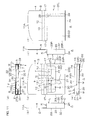
- FIG. 4 is an expansion plan view of the main portion C of the packaging container A.
- FIGS. 5 are perspective views of the main portion C in a complete state.
- FIGS. 6 are six side views of the main portion C in the complete state.
- the main portion C is fabricated from a crease pattern Y made of a single paper sheet as shown FIG. 4 .
- the crease pattern Y is formed by cutting the single paper sheet (cardboard or the like) according to the expansion plan view of the main portion C.
- the crease pattern Y i.e., the main portion C as seen in the expansion plan view, includes a horizontally elongated generally U-shaped packaging container front wall 20 having the same size as the rear chamber front wall 16 (see FIG. 2 ) described above. Therefore, the packaging container front wall 20 has a take-out window G provided in an upper portion thereof and having the same size as the take-out window D (see FIG. 2 ) of the rear chamber front wall 16.
- the take-out window G is a cut-out portion extending from an upper edge of the packaging container front wall 20.
- the packaging container front wall 20 has an incision 21 provided in a center position of a lower portion thereof below the take-out window G and having the same shape as the incision 9 (see FIG. 2 ) of the front extension plate 8.
- the incision 21 has a vertically inverted generally M-shape in FIG. 4 , and extends thicknesswise through the packaging container front wall 20.
- the packaging container front wall 20 has a left edge 20L and a right edge 20R vertically extending parallel to each other, and a lower edge 20D laterally (horizontally) extending perpendicularly to the left edge 20L and the right edge 20R.
- the main portion C as seen in the expansion plan view includes a packaging container left side wall 22 which is continuous leftward from the left edge 20L, a packaging container right side wall 23 which is continuous rightward from the right edge 20R, and a front chamber bottom wall 24 which is continuous downward from the lower edge 20D.
- the packaging container left side wall 22 and the packaging container right side wall 23 each have a vertically elongated rectangular shape, and have the same size.
- the front chamber bottom wall 24 has a horizontally elongated rectangular shape.
- the longitudinal dimensions of the packaging container left side wall 22 and the packaging container right side wall 23 are equal to the (maximum) widthwise dimension of the packaging container front wall 20.
- the longitudinal dimension of the front chamber bottom wall 24 is equal to the longitudinal dimension of the packaging container front wall 20.
- the widthwise dimensions of the packaging container left side wall 22 and the packaging container right side wall 23 are approximately twice the widthwise dimension of the front chamber bottom wall 24.
- the main portion C as seen in the expansion plan view includes a left extension plate 25 which is continuous leftward from an edge (left edge in FIG. 4 ) 22L of the packaging container left side wall 22 opposite from the left edge 20L, a right extension plate 26 which is continuous rightward from an edge (right edge in FIG. 4 ) 23R of the packaging container right side wall 23 opposite from the right edge 20R, and a front chamber rear wall 27 which is continuous downward from an edge (lower edge in FIG. 4 ) 24D of the front chamber bottom wall 24 opposite from the lower edge 20D.
- the left extension plate 25 has a horizontally elongated rectangular shape.
- the left extension plate 25 has a longitudinal dimension that is equal to the longitudinal dimension of the packaging container front wall 20, and a widthwise dimension that is equal to the (maximum) widthwise dimension of the packaging container front wall 20.
- the left extension plate 25 has a pair of perforation lines 28 provided laterally adjacent to the packaging container left side wall 22 and extending vertically in a widthwise direction thereof across the left extension plate 25. A portion of the left extension plate 25 defined between the pair of perforation lines 28 serves as a zipper band portion 29 extending vertically.
- the right extension plate 26 has a vertically elongated isosceles trapezoidal shape having a lower base defined by the right edge 23R of the packaging container right side wall 23 and tapered toward an upper base thereof (rightward away from the right edge 23R in FIG. 4 ).
- the front chamber rear wall 27 has a horizontally elongated rectangular shape.
- the front chamber rear wall 27 has a longitudinal dimension that is equal to the longitudinal dimension of the front chamber bottom wall 24, and a widthwise dimension that is smaller than the widthwise dimension of the left extension plate 25, e.g., approximately three fourths the widthwise dimension of the left extension plate 25.
- the main portion C as seen in the expansion plan view has an engagement piece 30 which is continuous downward from a horizontally middle portion of a distal edge (lower edge) 27A of the front chamber rear wall 27 opposite from the lower edge 24D of the front chamber bottom wall 24.
- the main portion C has a perforation line 31 provided along the distal edge 27A between the front chamber rear wall 27 and the engagement piece 30 as extending horizontally.
- the engagement piece 30 has a horizontally elongated isosceles trapezoidal shape having a lower base defined by the perforation line 31 and tapered toward an upper base thereof (downward away from the perforation line 31 in FIG. 4 ).
- the engagement piece 30 may be regarded as a part of the front chamber rear wall 27.
- the packaging container left side wall 22 (left extension plate 25), the packaging container right side wall 23 (right extension plate 26) and the front chamber bottom wall 24 (front chamber rear wall 27 and engagement piece 30) of the crease pattern Y are folded to the same side (rearward of the paper face in FIG. 4 ) perpendicularly to the packaging container front wall 20 along corresponding folding lines defined by the left edge 20L, the right edge 20R and the lower edge 20D of the packaging container front wall 20.
- the front chamber rear wall 27 (engagement piece 30) is folded upward perpendicularly to the front chamber bottom wall 24 along the lower edge 24D of the front chamber bottom wall 24.
- the front chamber rear wall 27 (engagement piece 30) is opposed to and spaced rearward (backward) from the packaging container front wall 20.
- the distal edge 27A of the front chamber rear wall 27 serves as an upper edge of the front chamber rear wall 27.
- the engagement piece 30 is folded (rearward) away from the packaging container front wall 20 along the perforation line 31 on the distal edge 27A.
- the left extension plate 25 and the right extension plate 26 are folded toward each other (horizontally inward) perpendicularly to the packaging container left side wall 22 and the packaging container right side wall 23 along corresponding folding lines defined by the left edge 22L of the packaging container left side wall 22 and the right edge 23R of the packaging container right side wall 23.
- a right edge portion left edge portion before the folding in FIG.
- FIGS. 5 (a) and 5 (b) are perspective views of the main portion C.
- the main portion C is seen from a position closer to the overhead position in FIG. 5(b) than in FIG. 5(a) .
- the left extension plate 25 and the right extension plate 26 bonded together cooperatively define a horizontally elongated rectangular packaging container rear wall 32.
- the packaging container rear wall 32 has the same size as the left extension plate 25.
- the band portion 29 of the left extension plate 25 is located slightly rightward away from the left edge of the packaging container rear wall 32 as extending vertically across the packaging container rear wall 32.
- the packaging container rear wall 32 can be divided into left and right portions on opposite sides of the band portion 29 by tearing off the band portion 29 along the perforation lines 28.
- the main portion C has a box shape which is anteroposteriorly flat (in a direction in which the packaging container front wall 20 and the packaging container rear wall 32 are opposed to each other), and has an accommodation space H defined by the packaging container front wall 20, the packaging container rear wall 32, the packaging container left side wall 22 and the packaging container right side wall 23.
- the front side of the paper face in FIGS. 5 is the front side of the main portion C, and the rear side of the paper face in FIGS. 5 is the rear side of the main portion C.
- the front chamber rear wall 27 is disposed between the packaging container front wall 20 and the packaging container rear wall 32 as extending parallel to the packaging container front wall 20 and the packaging container rear wall 32, whereby the accommodation space H is anteroposteriorly partitioned into two spaces generally, i.e., a front space I adjacent to the packaging container front wall 20 (on the front side) and a rear space J adjacent to the packaging container rear wall 32 (on the rear side).
- the front chamber rear wall 27 is a partition wall which partitions the accommodation space H (the inside of the main portion C or the packaging container A).
- the front space I and the rear space J are anteroposteriorly flat box-shaped spaces having substantially the same size.
- the front chamber rear wall 27 has a smaller height than the packaging container rear wall 32. Therefore, the distal edge 27A (upper edge) of the front chamber rear wall 27 is located at a lower height level than the upper edge of the packaging container rear wall 32. Thus, the front space I and the rear space J communicate with each other above the front chamber rear wall 27. Since the height of the front chamber rear wall 27 is smaller than the height of the packaging container rear wall 32, it is possible to prevent the height increase of the entire main portion C (in other words, the entire packaging container A) due to the provision of the front chamber rear wall 27.
- the engagement piece 30 of the front chamber rear wall 27 is folded back to the rear space J.
- An upper end of the accommodation space H is open upward to serve as a take-out port K defined from lateral sides by upper edges of the packaging container left side wall 22 and the packaging container right side wall 23 and having a horizontally elongated rectangular shape.
- the take-out port K is continuous to the take-out window G of the packaging container front wall 20.
- the front space I which is a generally front half portion of the accommodation space H, has a lower end closed with the front chamber bottom wall 24 (see FIG. 5(b) ) and an upper end which is open upward to define a generally front half portion of the take-out port K.
- An upper portion of the front space I is open forward from the take-out window G.
- the front chamber L is constituted by the packaging container front wall 20, the front chamber rear wall 27, the front chamber bottom wall 24, and generally front half portions of the packaging container left side wall 22 and the packaging container right side wall 23, which cooperatively define the front space I of the accommodation space H.
- the front chamber L may further include generally rear half portions of the packaging container left side wall 22 and the packaging container right side wall 23, and the packaging container rear wall 32. In this case, the entire main portion C serves as the front chamber L.
- the rear space J which is a generally rear half portion of the accommodation space H, has a lower end having a horizontally elongated rectangular shape and opening downward to serve as an insertion port M (to be described later with reference to FIG. 6(e) ) defined anteroposteriorly by lower edges of the front chamber rear wall 27 and the packaging container rear wall 32, and an upper end which opens upward to define a generally rear half portion of the take-out port K. That is, the rear space J is a space located between the front chamber rear wall 27 and the packaging container rear wall 32 and having upper and lower openings.
- FIGS. 6 are diagrams for explaining how to individually wrap a chewing gum piece 40 (food strip) with a wrapping sheet 41 to provide a food unit 42.
- the chewing gum piece 40 has a vertically-elongated rectangular-solid thin block shape (elongated strip shape).
- the longitudinal dimension of the chewing gum piece 40 is slightly smaller than the widthwise dimensions of the rear chamber rear wall 1 (see FIG. 2 ) of the rear chamber B and the packaging container rear wall 32 (see FIGS. 5 ).
- the chewing gum piece 40 is wrapped with the wrapping sheet 41.
- the food unit 42 is constituted by the chewing gum piece 40 and the wrapping sheet 41 which wraps the chewing gum piece 40.
- the wrapping sheet 41 examples include a so-called foil paper sheet, a wax paper sheet and a film.
- the wrapping sheet 41 In an expanded state, the wrapping sheet 41 is a rectangular sheet which is large enough to wrap the chewing gum piece 40.
- the wrapping sheet 41 has a perforation line 43 provided closer to one of longitudinally opposite edges as extending widthwise of the wrapping sheet 41 across the wrapping sheet 41.
- FIG. 7 (a) a single chewing gum piece 40 is placed on a center portion of a single wrapping sheet 41 with its longitudinal axis aligning with the longitudinal axis of the wrapping sheet 41. Portions of the wrapping sheet 41 protruding from the chewing gum piece 40 are folded, whereby the chewing gum piece 40 is wrapped with the wrapping sheet 41 as shown in FIG. 7(b) .
- the food unit 42 is provided by thus wrapping (individually wrapping) the chewing gum piece 40 with the wrapping sheet 41.
- the food unit 42 has a vertically elongated block shape having a size that is slightly greater than the chewing gum piece 40 by the thickness of the wrapping sheet 41. With the food unit 42 vertically postured, the perforation line 43 of the wrapping sheet 41 of the food unit 42 is located in a longitudinal (vertical) position closer to the lower edge thereof as extending (horizontally) widthwise of the food unit 42 to surround the chewing gum piece 40.
- the perforation line 43 divides the wrapping sheet 41 wrapping the chewing gum piece 40 into a separation portion 41A located on an upper side of the perforation line 43 and a fixing portion 41B located on a lower side of the perforation line 43.
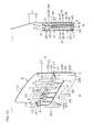
- FIGS. 8 (a), 8(b), 8(c) and 8(d) are a perspective view illustrating the rear chamber B in the complete state with food units accommodated therein, a cross sectional view of the rear chamber B of FIG. 8(a) , a perspective view illustrating the main portion C in the complete state with food units 42 accommodated therein, and a cross sectional view of the main portion C of FIG. 8(c) , respectively.
- FIG. 8(a) six food units 42 out of the twelve food units 42 (chewing gum pieces 40) are contained upright in side-by-side relation in the accommodation space E of the rear chamber B.
- an adhesive agent (which may be an adhesive tape) 45 is applied to a horizontally extending zone on a lower edge portion of a front surface of the rear chamber rear wall 1 of the rear chamber B facing to the accommodation space E.
- the fixing portions 41B of the wrapping sheets 41 of the respective food units 42 are bonded to the rear chamber rear wall 1 by the adhesive agent 45 in the accommodation space E.
- FIG. 8(a) With the six food units 42 accommodated in the accommodation space E (in the rear chamber B), as shown in FIG. 8(a) , upper portions of the food units 42 are exposed forward from the take-out window D of the rear chamber front wall 16 and exposed upward from the take-out port F.
- the food units 42 to be accommodated in the rear chamber B are bonded to the rear chamber rear wall 1 of the crease pattern X (see FIG. 1 ).
- the rear chamber B is completed with the food units 42 accommodated in the accommodation space E.
- the food units 42 may be accommodated in the rear chamber B after the fabrication.
- the other six food units 42 out of the twelve food units 42 are contained upright in side-by-side relation in the front space I of the front chamber L of the main portion C. As shown in FIG.
- an adhesive agent (which may be an adhesive tape) 46 is applied to a horizontally extending zone on a lower edge portion of a front surface of the front chamber rear wall 27 of the front chamber L.
- the fixing portions 41B of the wrapping sheets 41 of the respective food units 42 are bonded to the front chamber rear wall 27 by the adhesive agent 46 in the front space I.
- upper portions of these food units 42 are exposed forward from the take-out window G of the packaging container front wall 20 and exposed upward from the take-out port K.
- the food units 42 to be accommodated in the front chamber L are bonded to the front chamber rear wall 27 of the crease pattern Y (see FIG. 4 ).
- the front chamber L main portion C
- the front chamber L is completed with the food units 42 accommodated in the front space I.
- the food units 42 may be accommodated in the front chamber L after the fabrication.
- the rear chamber B is combined with the main portion C to complete the packaging container A.
- FIG. 9 is an exploded perspective view for explaining a state in which the rear chamber B is combined with the main portion C.
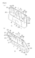
- FIG. 10(a) is a perspective view of the packaging container A in the complete state with the lid 4 open
- FIG. 10(b) is a sectional view of the packaging container A of FIG. 10 (a) as seen from a right side.
- FIGS. 11 are six side views of the packaging container A in the complete state.
- the lid 4 of the rear chamber B is opened.
- the lid 4 extends upward from the upper edge (upper edge 1U) of the rear chamber rear wall 1, and is generally flush with the rear chamber rear wall 1.
- the rear chamber B is opposed to the rear half portion of the take-out port K of the main portion C from above, and then the rear chamber B and the main portion C are relatively moved so that the rear chamber bottom wall 5 of the rear chamber B is inserted into the rear half portion of the take-out port K. Therefore, the rear chamber B may be moved to the main portion C with the main portion C kept stationary or, conversely, the main portion C may be moved to the rear chamber B.
- the rear chamber B is inserted into the rear half portion of the take-out port K to be thereby accommodated in the rear space J of the main portion C.
- the first lid portion 10 of the lid 4 has the left and right stoppers 17 and, therefore, has the greatest horizontal dimension (is broadest) in the rear chamber B and the main portion C. Therefore, when a portion of the rear chamber B other than the lid 4 is completely accommodated in the rear space J of the main portion C as shown in FIGS. 10 , the stoppers 17 provided on the left and right sides of the first lid portion 10 of the lid 4 respectively abut against (engage with) the upper edges of the packaging container left side wall 22 and the packaging container right side wall 23 of the main portion C from above.
- the lid 4 completely protrudes upward from the take-out port K of the main portion C.
- the upper edges of the rear chamber rear wall 1, the rear chamber left side wall 2, the rear chamber right side wall 3 and the rear chamber front wall 16 of the rear chamber B provided behind the front chamber L are located at the same height level as the upper edges of the packaging container front wall 20, the packaging container left side wall 22, the packaging container right side wall 23 and the packaging container rear wall 32 of the main portion C.
- the lower edges of the rear chamber rear wall 1, the rear chamber left side wall 2, the rear chamber right side wall 3 and the rear chamber front wall 16 are located at the same height level as the lower edges of the packaging container front wall 20, the packaging container left side wall 22, the packaging container right side wall 23, the front chamber rear wall 27 and the packaging container rear wall 32. Therefore, when the packaging container A is seen from the front side, the rear chamber B (except for the lid 4) completely overlaps with the front chamber L of the main portion C. At this time, the food units 42 contained in the rear chamber B and the food units 42 contained in the front chamber L are located at the same height level, so that upper edges of all the food units 42 are located at the same height level.
- the upper edge of the front extension plate 8 of the rear chamber front wall 16 of the rear chamber B is opposed to and spaced a predetermined distance from the engagement piece 30 of the front chamber rear wall 27 of the main portion C (more strictly, a portion around a connection between the folded engagement piece 30 and the front chamber rear wall 27).
- the rear space J in which the rear chamber B is accommodated has upper and lower open ends, so that the rear chamber B is vertically slidable with respect to the front chamber L (main portion C) in the rear space J.
- the upper edge of the front extension plate 8 of the rear chamber B engages with the engagement piece 30 of the front chamber L from below as will be described later, so that the upward slidable distance of the rear chamber B is limited to a predetermined distance.
- the completed packaging container A is of a slidable configuration, and has an anteroposteriorly flat box shape.
- the front side of the paper face in FIG. 10 (a) is the front side of the packaging container A
- the rear side of the paper face in FIG. 10(a) is the rear side of the packaging container A.
- FIGS. 11 illustrates six side views of the packaging container A.
- FIG. 12 illustrates a state in which the lid 4 is closed in FIG. 10(a) .
- the lid 4 is still open as shown in FIG. 10(a) , and extends upward from the upper edge of the rear chamber rear wall 1 (upper edge 1U).
- the lid 4 is folded forward perpendicularly to the rear chamber rear wall 1 along the upper edge 1U of the rear chamber rear wall 1.
- the second lid portion 11 of the lid 4 is folded downward perpendicularly to the first lid portion 10 along the fist folding guide 12.
- the lid 4 is closed as shown in FIG. 12 .
- the lid 4 serves as a flap.
- the first lid portion 10 of the lid 4 covers the upper wall of the packaging container A, and the second lid portion 11 of the lid 4 covers the front upper portion of the packaging container A (the upper portion of the packaging container front wall 20). Therefore, the take-out port K of the main portion C in the upper wall of the packaging container A is closed with the first lid portion 10.
- the first lid portion 10 defines the upper wall of the packaging container A. In this case, there is no need to provide a flap for each of the front chamber L and the rear chamber B to cover the upper wall and the front upper portion of the packaging container A, thereby reducing the number of components.
- the second folding guide 13 which divides the first lid portion 10 into the first piece 14 and the second piece 15 is provided in an anteroposteriorly middle portion of the first lid portion 10 (the upper wall of the packaging container A) as extending horizontally.
- the take-out window G provided in the upper portion of the packaging container front wall 20 is closed with the second lid portion 11.
- the distal edge 11A of the second lid portion 11 is inserted into the incision 21 of the packaging container front wall 20, whereby the second lid portion 11 is engaged with the packaging container front wall 20 so as to prevent the lid 4 from being withdrawn.
- the lid 4 is kept closed.
- the packaging container A with the lid 4 closed is like a mailing envelope.
- FIGS. 13 illustrate a state in which one of the food units 42 is taken out of the main portion C, particularly, FIGS. 13(a) and 13(b) are a perspective view from the same position as in FIG. 10(a) and a sectional view from the same position as in FIG. 10 (b) , respectively.
- FIGS. 14 illustrate a state in which one of the food units 42 is taken out of the rear chamber B, particularly, FIGS. 14 (a) and 14 (b) are a perspective view from the same position as in FIG. 13(a) and a sectional view from the same position as in FIG. 13 (b) , respectively.
- FIG. 15 is a perspective view of the packaging container A in which the food units 42 are accommodated in the rear chamber B and the main portion C, and the rear chamber B is slid upward.
- the distal edge 11A of the second lid portion 11 is disengaged from the incision 21 of the packaging container front wall 20 to open the lid 4 as shown in FIGS. 13 .
- an eater is to sequentially eat the chewing gum pieces 40 located in the front row in the front chamber L of the packaging container A.
- the upper portions (the separation portions 41A of the wrapping sheets 41) of the food units 42 (chewing gum pieces 40) contained in the front chamber L are exposed forward from the take-out window G provided in the upper portion of the packaging container front wall 20 of the front chamber L (main portion C).
- any one of the chewing gum pieces 40 contained in the front chamber L can be accessed from the take-out window G to be easily picked by finger tips 100. Then, the food unit 42 thus picked by the finger tips 100 is pulled up from the take-out port K of the main portion C as indicated by a bold arrow.
- the fixing portions 41B of the wrapping sheets 41 are fixed to the main portion C by the adhesive agent 46, so that the separation portion 41A and the fixing portion 41B of the wrapping sheet 41 of the food unit 42 thus picked out are separated from each other.
- the picked food unit 42 is further picked out of the front chamber L with the separation portion 41A combined with the wrapped chewing gum piece 40.
- the other food units 42 are fixed to the main portion C by the adhesive agent 46, so that these food units 42 are not displaced in the front chamber L.
- the eater can eat the chewing gum piece 40, while holding a portion of the chewing gum piece 40 of the picked food unit 42 exposed from the separation portion 41A by eater's mouth.
- the eater picks out the other food units 42 from the front chamber L in the same manner to eat the chewing gum pieces 40 of the respective food units 42.
- the wrapping sheet not formed with the perforation line 43 is used as the wrapping sheet 41, or where the chewing gum pieces 40 are each individually wrapped with a transparent film 51 or a plastic case 52 according to a modification to be described later (to be described with reference to FIGS. 18 )
- the entire food unit 42 thus individually wrapped can be picked out, while the wrapping sheet, the transparent film 51 or the case 52 is entirely disconnected from the adhesive agent 46.
- the rear chamber B is pulled up (for example, by holding the lid 4).
- the rear chamber bottom wall 5 exposed from the insertion port M of the main portion C may be pushed up.
- the rear chamber B is slid upward with respect to the front chamber L (main portion C).
- the rear chamber B is prevented from being moved further upward with respect to the front chamber L.
- the rear chamber B is thus combined with the front chamber L, so that the front extension plate 8 can be slid upward by the predetermined distance Z to be brought into engagement with the engagement piece 30.
- the rear chamber B and the front chamber L are located in offset relation.
- the upper portions of the food units 42 in the rear chamber B also project upward from the take-out port K of the main portion C. Since the upper portions of the food units 42 (the separation portions 41A of the packaging sheets 41) are exposed forward from the take-out window D provided in the upper portion of the rear chamber B, the food units 42 (chewing gum pieces 40) contained in the rear chamber B can be accessed from the take-out window D to be easily picked by the finger tips 100. In turn, the food unit 42 thus picked by the finger tips 100 is pulled up from the take-out port F of the rear chamber B as indicated by a bold arrow.
- the fixing portions 41B of the wrapping sheets 41 are fixed to the rear chamber B by the adhesive agent 45, so that the separation portion 41A and the fixing portion 41B of the wrapping sheet 41 of the picked food unit 42 are separated from each other.
- the picked food unit 42 is further picked out of the rear chamber B with the separation portion 41A combined with the wrapped chewing gum piece 40.
- the other food units 42 are fixed to the rear chamber B by the adhesive agent 45, so that these food units 42 are not displaced in the rear chamber B.
- the eater can eat the chewing gum piece 40, while holding a portion of the chewing gum piece 40 exposed from the separation portion 41A of the picked food unit 42 by eater's mouth.
- the eater picks out the other food units 42 from the rear chamber B in the same manner to eat the chewing gum pieces 40 of the respective food units 42. If some of the food units 42 remain in the rear chamber B, the rear chamber B may be slid downward by the predetermined distance Z. Thus, the rear chamber B (except for the lid 4) is completely accommodated in the rear space J of the main portion C (see FIGS. 10 ).
- the left and right stoppers 17 of the first lid portion 10 of the lid 4 respectively abut against the packaging container left side wall 22 and the packaging container right side wall 23 of the main portion C from above.
- the rear chamber B accommodated in the rear space J is prevented from being withdrawn from the insertion port M provided in the bottom of the main portion C.
- the rear chamber B is combined with the front chamber L so as to be slidable upward with respect to the front chamber L by the predetermined distance Z. Therefore, the chewing gum pieces 40 contained in the rear row (rear chamber B) can be located at a higher height level than the chewing gum pieces 40 contained in the front row (front chamber L) (see FIG. 15 ) by sliding the rear chamber B upward with respect to the front chamber L as required without preliminarily providing a raised bottom portion in the rear portion of the packaging container A to locate the rear row chewing gum pieces 40 at a higher height level than the front row chewing gum pieces 40. This obviates the need for providing the raised bottom portion, thereby achieving the size reduction of the packaging container A.
- the packaging container A satisfies the requirements for the compactness of the container and the pick-out easiness for picking out each of the food pieces (chewing gum pieces 40) contained in a plurality of rows in anteroposteriorly overlapping relation.
- the chewing gum pieces 40 of the food units 42 contained in the rear chamber B may be first eaten with the rear chamber B slid upward before the food units 42 contained in the front chamber L are taken out as shown in FIG. 15 . If not all the chewing gum pieces 40 are eaten, the lid 4 is closed with some of the chewing gum pieces 40 of the food units 42 left in the front chamber L and the rear chamber B (see FIG. 12 ).
- FIG. 16 is a perspective view illustrating a state in which the band portion 29 of the main portion C is torn off.
- FIG. 17 is a perspective view of the rear chamber B in the complete state with the lid 4 closed. Where all the chewing gum pieces 40 contained in the front chamber L are eaten up with the food units 42 remaining in the rear chamber B, the band portion 29 of the packaging container rear wall 32 of the main portion C is torn off as shown in FIG. 16 . Then, the packaging container rear wall 32 is divided into the left portion and the right portion, so that only the rear chamber B can be taken out of the rear space J through a space between the left portion and the right portion of the packaging container rear wall 32.
- the rear chamber B is thus decombined from the main portion C (front chamber L) to thereby provide an independently usable package. Therefore, where the front chamber L becomes a dead space after all the chewing gum pieces 40 contained in the front chamber L are eaten up (see FIG. 14 ), the rear chamber B is separated from the front chamber L.
- the rear chamber B which has a thickness approximately half the thickness of the original packaging container A can be compactly carried with the remaining chewing gum pieces 40 contained therein. That is, after some of the chewing gum pieces 40 are eaten, a part of the packaging container A having a reduced size (reduced thickness) can be conveniently used.
- a crease formed along the first folding guide 12 of the lid 4 is removed. That is, a crease present between the second piece 15 defining the front portion of the first lid portion 10 (the upper wall of the packaging container A) and the second lid portion 11 defining the flap of the packaging container A is removed. Thus, the first lid portion 10 and the second lid portion 11 become flush with each other.
- the second piece 15 and the second lid portion 11 are folded forward and downward perpendicularly to the first piece 14 (along the second folding guide 13) to form a crease along the second folding guide 13.
- the lid 4 is closed as shown in FIG. 17 .
- the first piece 14 defining the rear portion of the first lid portion 10 of the lid 4 serves as an upper wall of the rear chamber B, while the second piece 15 and the second lid portion 11 function as a flap covering a front portion of the rear chamber B.
- the lid 4 of the rear chamber B serves as the flap of the entire packaging container A (see FIG. 12 ).
- the lid 4 of the rear chamber B serves as the flap of the rear chamber B (see FIG. 17 ).
- the first piece 14 of the first lid portion 10 of the lid 4 covers the upper wall of the rear chamber B, while the second piece 15 and the second lid portion 11 of the lid 4 cover the front upper portion of the rear chamber B (the upper portion of the rear chamber front wall 16). Therefore, the take-out port F provided in the upper wall of the rear chamber B is closed with the first piece 14, while the take-out window D provided in the upper portion of the rear chamber front wall 16 is closed with the second piece 15 and the second lid portion 11.
- the lid 4 covers the front portion and the upper portion of the rear chamber B, thereby preventing the chewing gum pieces 40 from being withdrawn forward out of the rear chamber B.
- the distal edge 11A of the second lid portion 11 is inserted in the incision 9 of the rear chamber front wall 16, whereby the lid 4 is engaged with the rear chamber front wall 16 to be maintained in a closed state so as not to be withdrawn from the rear chamber front wall 16.
- the rear chamber B with the lid 4 closed is like a mailing envelope.
- the strip-shaped chewing gum pieces 40 are each individually wrapped with a wrapping sheet 41 to provide the food unit 42.
- the food unit 42 is not limited to that prepared by wrapping (individually wrapping) the chewing gum piece with the wrapping sheet 41.
- the food unit 42 may be prepared by covering a strip-shaped chewing gum piece 40 with transparent films 51 and then heat-sealing upper, lower, left and right peripheral portions of the transparent films 51 to provide heat-seal portions 51h to seal the chewing gum piece 40 between the transparent films 51. In this case, a slight gap may be left between the transparent films 51 and the chewing gum piece 40 when the chewing gum piece 40 is sealed.
- the chewing gum piece 40 may be sealed after the inside space is evacuated to remove the gap.
- the transparent films 51 intimately contact the chewing gum piece 40, so that the chewing gum piece 40 is not exposed to the outer atmosphere. This improves the quality protection of the chewing gum piece 40.
- the transparent films 51 may each have a perforation line or a fragile line to be divided into upper and lower portions along the line, so that the chewing gum piece 40 can be taken out with its lower portion exposed.
- the strip-shaped chewing gum piece 40 may be sealed in a plastic case 52 to provide the food unit 42.
- the strip-shaped chewing gum pieces 40 can be compactly contained upright in side-by-side relation with their laterally opposite edge portions overlapped at a predetermined pitch. Further, the appearance can be improved. It should be understood that the present invention be not limited to the embodiment described above, but various modifications may be made within the scope of the present invention defined by the claims.
- the food units 42 are accommodated in the front chamber L and the rear chamber B to be contained in the two rows, i.e., in the front and rear rows by way of example (see FIGS. 10 ).
- the food units 42 may be contained in three or more rows arranged anteroposteriorly with provision of a plurality of rear chambers B.
- the rear chambers B are pull up stepwise, so that the food units 42 can be easily picked out from the respective rear chambers B.
- the front chamber L and the rear chamber B are each adapted to contain six food units 42 in side-by-side relation, but the number of the food units 42 to be contained in each of the front chamber L and the rear chamber B may be properly changed.
- the food units 42 are each arranged so that the wrapping sheet 41 is divided into the separation portion 41A and the fixing portion 41B when the food unit 42 is taken out of the packaging container A (see FIGS. 13 and 14 ), but the wrapping sheet 41 is not necessarily required to be divided. In this case, there is no need to provide the perforation line 43 in the wrapping sheet 41, and the food unit 42 is taken out of the packaging container A without the division of the wrapping sheet 41.
- the food units 42 are preferably temporarily (weakly) bonded to the packaging container A (the rear chamber B and the main portion C, see FIGS. 13 and 14 ) by the adhesive agent 45, 46, so that the food units 42 can be easily taken out of the packaging container A without breaking the wrapping sheets 41.
- a necessary number of food units 42 may be first bundled with bundling sheets (not shown), and then the resulting bundles of food units 42 may be respectively set in the front chamber L and the rear chamber B.
- the bundles of the food units 42 may be respectively bonded to the crease patterns X and Y (see FIGS. 1 and 4 ) before the fabrication of the front chamber L and the rear chamber B.
- the front chamber L and the rear chamber B are thereafter fabricated, the bundles of the food units 42 are respectively accommodated in the front chamber L and the rear chamber B.
- the distal edge 11A of the second lid portion 11 is inserted into the incision 9, 21 (see FIGS. 12 and 17 ) not by way of limitation, but a chevron-shaped incision provided in a center portion of the second lid portion 11 or in a portion of the second lid portion 11 adjacent to the distal edge 11A may be engaged with the incision 9, 21.
- the rear chamber B may be first accommodated in the rear space J to be combined with the main portion C without bonding the left extension plate 25 and the right extension plate 26 of the main portion C to each other. Then, the packaging container A may be completed by bonding the left extension plate 25 and the right extension plate 26 together (see FIG. 9 ).
- the chewing gum pieces are employed as the strips to be contained in the packaging container A, but other examples of the strips include chocolate strips and candy strips.
Landscapes
- Engineering & Computer Science (AREA)
- Mechanical Engineering (AREA)
- Cartons (AREA)
- Packging For Living Organisms, Food Or Medicinal Products That Are Sensitive To Environmental Conditiond (AREA)
- Packages (AREA)
- Confectionery (AREA)
Applications Claiming Priority (2)
| Application Number | Priority Date | Filing Date | Title |
|---|---|---|---|
| JP2011038540 | 2011-02-24 | ||
| PCT/JP2012/053558 WO2012114960A1 (fr) | 2011-02-24 | 2012-02-15 | Réceptacle d'emballage et confiserie dans réceptacle d'emballage |
Publications (1)
| Publication Number | Publication Date |
|---|---|
| EP2679509A1 true EP2679509A1 (fr) | 2014-01-01 |
Family
ID=46720742
Family Applications (1)
| Application Number | Title | Priority Date | Filing Date |
|---|---|---|---|
| EP12749600.8A Withdrawn EP2679509A1 (fr) | 2011-02-24 | 2012-02-15 | Réceptacle d'emballage et confiserie dans réceptacle d'emballage |
Country Status (10)
| Country | Link |
|---|---|
| US (1) | US20130323356A1 (fr) |
| EP (1) | EP2679509A1 (fr) |
| JP (1) | JP6057433B2 (fr) |
| KR (1) | KR101893068B1 (fr) |
| CN (1) | CN103402880A (fr) |
| BR (1) | BR112013021777A2 (fr) |
| CO (1) | CO6761326A2 (fr) |
| PH (1) | PH12013501691A1 (fr) |
| TW (1) | TW201245011A (fr) |
| WO (1) | WO2012114960A1 (fr) |
Families Citing this family (1)
| Publication number | Priority date | Publication date | Assignee | Title |
|---|---|---|---|---|
| CN113247406A (zh) * | 2021-05-12 | 2021-08-13 | 美盈森集团股份有限公司 | 一种显示器包装盒 |
Family Cites Families (13)
| Publication number | Priority date | Publication date | Assignee | Title |
|---|---|---|---|---|
| JPS447833Y1 (fr) * | 1966-06-03 | 1969-03-25 | ||
| JPH047833Y2 (fr) * | 1986-07-16 | 1992-02-28 | ||
| JPH0536817Y2 (fr) * | 1988-05-20 | 1993-09-17 | ||
| JP3955355B2 (ja) | 1997-06-12 | 2007-08-08 | 大日本印刷株式会社 | 包装用箱及び該箱と板状内容物とからなる包装体 |
| JP3955356B2 (ja) * | 1997-06-12 | 2007-08-08 | 大日本印刷株式会社 | 包装用箱、該箱と板状内容物からなる包装体、及び該包装体の製造方法 |
| US7032754B2 (en) * | 2001-10-31 | 2006-04-25 | Wm. Wrigley Jr. Company | Package having releaseably secured consumable products |
| EP1753669B1 (fr) * | 2004-05-11 | 2011-04-27 | Cadbury Adams USA LLC | Paquet permettant de distribuer et de retenir des dalles de gomme au moyen d'une fixation adhesive |
| US7159717B2 (en) * | 2004-05-11 | 2007-01-09 | Cadbury Adams Usa, Llc | Packaging design with separate compartments |
| CN100564193C (zh) * | 2004-05-11 | 2009-12-02 | 美国卡德伯里亚当斯有限公司 | 具有单独隔室的包装设计 |
| KR200392220Y1 (ko) | 2005-05-18 | 2005-08-19 | 주식회사 호텔신라 | 포장상자 |
| ITBO20070430A1 (it) * | 2007-06-18 | 2008-12-19 | Sergio Mezzini | Confezione perfezionata con mezzi di ritenzione del prodotto a forza controllata. |
| JP5237603B2 (ja) * | 2007-09-21 | 2013-07-17 | 株式会社ロッテ | 包装容器 |
| US8006860B2 (en) * | 2007-12-14 | 2011-08-30 | Marianne Christine Klein | Portable gum container |
-
2012
- 2012-02-15 EP EP12749600.8A patent/EP2679509A1/fr not_active Withdrawn
- 2012-02-15 KR KR1020137023015A patent/KR101893068B1/ko not_active Expired - Fee Related
- 2012-02-15 US US14/000,769 patent/US20130323356A1/en not_active Abandoned
- 2012-02-15 BR BR112013021777A patent/BR112013021777A2/pt not_active IP Right Cessation
- 2012-02-15 JP JP2013500979A patent/JP6057433B2/ja not_active Expired - Fee Related
- 2012-02-15 WO PCT/JP2012/053558 patent/WO2012114960A1/fr not_active Ceased
- 2012-02-15 PH PH1/2013/501691A patent/PH12013501691A1/en unknown
- 2012-02-15 CN CN2012800099641A patent/CN103402880A/zh active Pending
- 2012-02-23 TW TW101105990A patent/TW201245011A/zh unknown
-
2013
- 2013-08-14 CO CO13193440A patent/CO6761326A2/es unknown
Non-Patent Citations (1)
| Title |
|---|
| See references of WO2012114960A1 * |
Also Published As
| Publication number | Publication date |
|---|---|
| CN103402880A (zh) | 2013-11-20 |
| JPWO2012114960A1 (ja) | 2014-07-07 |
| KR101893068B1 (ko) | 2018-08-29 |
| PH12013501691A1 (en) | 2013-09-16 |
| WO2012114960A1 (fr) | 2012-08-30 |
| CO6761326A2 (es) | 2013-09-30 |
| KR20140010059A (ko) | 2014-01-23 |
| JP6057433B2 (ja) | 2017-01-11 |
| US20130323356A1 (en) | 2013-12-05 |
| TW201245011A (en) | 2012-11-16 |
| BR112013021777A2 (pt) | 2016-10-18 |
Similar Documents
| Publication | Publication Date | Title |
|---|---|---|
| EP2138411B1 (fr) | Ensemble d'articles à forme allongée | |
| CN100339277C (zh) | 一种硬质的烟包盒 | |
| WO2007140916A2 (fr) | Emballage | |
| US8066177B2 (en) | Receptacles, such as boxes, and packaging arrangements which include such receptacles | |
| HK1247601A1 (en) | Improved resealable container with label with adhesive free area | |
| KR101355762B1 (ko) | 일체형 추가패널들을 구비한 힌지식 뚜껑 용기 | |
| CN105050904A (zh) | 显窃启容器 | |
| EA025032B1 (ru) | Обернутая упаковка и способ ее изготовления | |
| WO2013130085A1 (fr) | Emballage pour produits consommables | |
| JP6689820B2 (ja) | たばこ用パッケージ | |
| EP2679509A1 (fr) | Réceptacle d'emballage et confiserie dans réceptacle d'emballage | |
| CN104334458A (zh) | 纸制包装容器 | |
| EP2487116B1 (fr) | Récipient d'emballage | |
| US20130330446A1 (en) | Food packaging container and packaging method | |
| HK1188765A (en) | Packaging container and confectionary in packaging container | |
| JP6193327B2 (ja) | 直方体形状包装パッケージ | |
| EP4619321A1 (fr) | Paquet rigide pour des articles à fumer comprenant une ouverture à inclinaison | |
| IT202200023634A1 (it) | Pacchetto di articoli da fumo rigido con apertura a basculamento | |
| WO2021018897A1 (fr) | Insert pour paquet d'articles à fumer | |
| JPH09150861A (ja) | 再封性のある上包み包装体 | |
| JP2016034856A (ja) | 直方体形状包装パッケージ | |
| HK1188766A (en) | Packaging container and packaging method for food | |
| HK1167848A (en) | Packaging container |
Legal Events
| Date | Code | Title | Description |
|---|---|---|---|
| PUAI | Public reference made under article 153(3) epc to a published international application that has entered the european phase |
Free format text: ORIGINAL CODE: 0009012 |
|
| 17P | Request for examination filed |
Effective date: 20130904 |
|
| AK | Designated contracting states |
Kind code of ref document: A1 Designated state(s): AL AT BE BG CH CY CZ DE DK EE ES FI FR GB GR HR HU IE IS IT LI LT LU LV MC MK MT NL NO PL PT RO RS SE SI SK SM TR |
|
| DAX | Request for extension of the european patent (deleted) | ||
| STAA | Information on the status of an ep patent application or granted ep patent |
Free format text: STATUS: THE APPLICATION HAS BEEN WITHDRAWN |
|
| 18W | Application withdrawn |
Effective date: 20150219 |