EP2679512A2 - Vorrichtung zum Ausgießen von Inhalten einer Flasche und Verfahren zum Öffnen einer solchen Vorrichtung - Google Patents
Vorrichtung zum Ausgießen von Inhalten einer Flasche und Verfahren zum Öffnen einer solchen Vorrichtung Download PDFInfo
- Publication number
- EP2679512A2 EP2679512A2 EP13151737.7A EP13151737A EP2679512A2 EP 2679512 A2 EP2679512 A2 EP 2679512A2 EP 13151737 A EP13151737 A EP 13151737A EP 2679512 A2 EP2679512 A2 EP 2679512A2
- Authority
- EP
- European Patent Office
- Prior art keywords
- button
- pourer
- bottle
- closure
- handgrip
- Prior art date
- Legal status (The legal status is an assumption and is not a legal conclusion. Google has not performed a legal analysis and makes no representation as to the accuracy of the status listed.)
- Withdrawn
Links
- 238000000034 method Methods 0.000 title claims abstract description 5
- 238000006073 displacement reaction Methods 0.000 claims abstract description 13
- 230000000903 blocking effect Effects 0.000 claims description 6
- 239000007788 liquid Substances 0.000 description 8
- 239000000463 material Substances 0.000 description 4
- 239000007787 solid Substances 0.000 description 2
- 230000000295 complement effect Effects 0.000 description 1
- 238000012986 modification Methods 0.000 description 1
- 230000004048 modification Effects 0.000 description 1
- 230000000717 retained effect Effects 0.000 description 1
- 238000005728 strengthening Methods 0.000 description 1
- 230000003245 working effect Effects 0.000 description 1
Images




Classifications
-
- B—PERFORMING OPERATIONS; TRANSPORTING
- B65—CONVEYING; PACKING; STORING; HANDLING THIN OR FILAMENTARY MATERIAL
- B65D—CONTAINERS FOR STORAGE OR TRANSPORT OF ARTICLES OR MATERIALS, e.g. BAGS, BARRELS, BOTTLES, BOXES, CANS, CARTONS, CRATES, DRUMS, JARS, TANKS, HOPPERS, FORWARDING CONTAINERS; ACCESSORIES, CLOSURES, OR FITTINGS THEREFOR; PACKAGING ELEMENTS; PACKAGES
- B65D47/00—Closures with filling and discharging, or with discharging, devices
- B65D47/04—Closures with discharging devices other than pumps
- B65D47/06—Closures with discharging devices other than pumps with pouring spouts or tubes; with discharge nozzles or passages
- B65D47/061—Closures with discharging devices other than pumps with pouring spouts or tubes; with discharge nozzles or passages with telescopic, retractable or reversible spouts, tubes or nozzles
- B65D47/063—Closures with discharging devices other than pumps with pouring spouts or tubes; with discharge nozzles or passages with telescopic, retractable or reversible spouts, tubes or nozzles with flexible parts
Definitions
- the present invention is related to a device for pouring the contents of a bottle, comprising a body intended to engage the neck of the bottle, and a pourer that is housed in said body and can axially slide therein.
- the device is manually actuated.
- the invention is also related to a method for opening such a device.
- An object of the present invention is to provide a simple and effective pouring device for bottles.
- the device comprises a body that houses a pourer and the latter only occupies a region of the body, the device further comprising a button that occupies another region of the body and, like the pourer, can axially slide therein; the button is linked to the pourer in a way such that an axial displacement of the button produces a corresponding but opposite axial displacement of the pourer, and vice versa.
- the link between the pourer and the button after opening the cap of the bottle the user can lift the pourer by simply pushing the button; after having poured the desired amount of oil or another liquid or pourable stuff, all the user has to do is to lower the pourer, for instance by placing the cap back on the bottle, thus moving the button back to its initial position.
- the pourer and the button can be made in a simple way.
- the button is linked to the pourer through a flexible joining strip (for example U-shaped), an end of which is connected to the bottom of the pourer and the other end of which is connected to the bottom of the button; additionally, the button, the pourer and the flexible joining strip may be integrally made in one piece.
- a flexible joining strip for example U-shaped
- the button and the pourer can be reliably linked, ensuring that the displacement of one easily produces the displacement of the other, and the assembly can be cheaply made, even as one piece.
- the body preferably comprises a bottom wall provided with at least one passageway, so that the pourer is located in correspondence with said passageway and the button is located in the region of the body that is substantially closed by said bottom wall.
- the bottom wall allows keeping the button region sufficiently isolated from the liquid being poured; besides, when the pourer and the button are linked through a flexible U-shaped joining strip, the bottom wall can be an abutment and a guide for the displacement of said joining strip.
- the inner surface of the body comprises two axial ribs that define the regions occupied by the pourer and the button and cooperate in guiding the pourer and the button.
- the button is configured as a substantially semi-cylindrical piece closed at least at the top and sides, and the pourer is configured as a substantially semi-cylindrical piece.
- the cross-section of the joint cylinder is a circle or an ellipse.
- the device also comprises blocking means for the button in an operative position thereof, in which the button is substantially completely inside the body and the pourer is mostly outside the body;
- this blocking means for the button may comprise a peg and a corresponding seat, one being formed in the body and the other being formed on the button, said peg being for example releasably snappable in said seat.
- the pressure applied by the user activates the blockage (for example, the peg snaps into the seat) and the button is retained in this position, thus keeping the pourer in a position suitable to dispense the liquid, without the need for the user to keep the finger on the button.
- the blockage can also be released by applying a pressure.
- the button preferably comprises an axial groove adjacent the blocking seat, the peg being able to slide within said groove during the displacement of the button; this groove prevents the peg from rubbing against the surface of the other piece during said displacement.
- the body comprises a double outer wall defining a hollow region open at the bottom and limited at the top by an annular wall; this wall preferably presents a hole for the intake of air. In this way the pouring of liquid is facilitated because an low-pressure area inside the bottle is avoided.
- the bottom wall analogously presents a hole for the intake of air.
- the device may further comprise a lid provided with a handgrip and a closure removably joined to the handgrip by at least one nub.
- the closure may comprise a pull-tab and a plug, the latter being inserted between the pourer and the button before the closure has been removed, shutting the pourer.
- a method for opening a device as described above comprises the steps of:
- the lid upon being placed when the pourer and the button are in an operative position, may push the pourer into the body, thus levelling the top of the pourer and the top of the button.
- the pourer upon covering the body with the lid, the pourer is lowered again into the body without the need for the user to touch the pourer (but in other cases the user may push the pourer with a finger); the pressure applied through the lid and the displacement of the pourer release the blockage of the button and restore the button to the initial position, by virtue of the link between the pourer and the button, so that the bottle can be closed without the pourer occupying an additional height.
- the directions are indicated as if the bottle were in an ordinary vertical position, with its axis in a vertical direction. Therefore, the "top portion" of an element located in the bottle's neck is a portion of said element oriented toward the outside of the bottle, whereas the "bottom portion” of an element located in the bottle's neck is a portion of said element oriented toward the inside of the bottle.
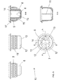
- a first embodiment of a device for pouring the contents of a bottle is shown in figures 1-6 .
- Said device comprises a body 10, a pourer 20 and a button 25, all made of a plastic material.
- the shape of the body 10 is generally cylindrical, with some variations, and the body comprises two axial ribs 11 that define two inner regions thereof. These regions are semi-cylinders when the ribs are diametrically opposed; if the ribs are not diametrically opposed said inner regions are other portions of the cylinder.
- One of said inner regions houses the pourer 20 and the other one houses the button 25.
- the body 10 can be fitted into a bottle's neck 100 by means of known engagements (for example the ribs/grooves 19/119 shown in fig. 6 ).
- the body 10 is partially closed at its bottom side by a wall 13, which is provided with an offset opening 12 located below the pourer 20, so that said wall 13 substantially closes the bottom portion of the body under the button 25.
- the contents of the bottle passes through the opening 12, whereby it directly reaches the pourer 20 and hardly reaches the button 25.
- a couple of elongated slots 9 are provided on the wall 13, said slots extending to the portion that lies below the button 25 to allow the intake of air when the liquid in the bottle is poured.
- the pourer 20 is trough-shaped and the button 25 is generally a semi-cylinder, at least in the shown embodiment, in which the ribs 11 are diametrically opposed.
- the bottom portion of the pourer 20 and the bottom portion of the button 25 are joined by a generally U-shaped flexible strip 29.
- the button 25 When the button 25 is lowered into the body 10, the portion of the flexible strip 29 near the button tends to be lowered as well, but, since the body is closed under the button by the wall 13, the strip 29 cannot descend beyond this wall and hence has to ascend by the portion that is near the pourer 20, whereby the latter is lifted and ends up mostly projecting out of the body 10, thus adopting an operative position.
- the device also comprises a generally discoid-shaped lid 30 that can be integrated in a bottle's cap (not shown).
- the lid 30 pushes the pourer 20 downward and the pourer 20, through the strip 29, drives the button upward, in a movement opposite the one described in the preceding paragraph, until both are substantially levelled.
- the lid 30 tightly engages an elastic projection 18, provided on the body 10, through a complementary elastic projection 38 provided on the lid 30; both projections 18 and 38 cooperate in a way such that the lid 30 and the body 10 may be snapped onto each other, until a force enough to pull them apart is applied.
- this feature facilitates the joint handling of the lid 30 and the body 10 during the operations for filling the bottle and placing the device on the bottle's neck.
- the body 10 is provided with a peg 14 in the top portion of its inner surface, located at approximately 90° from each axial rib 11.
- the button 25 comprises a seat 26 for the peg 14, so that the engagement between the peg 14 and the seat 26 fixes the button 25 to the body 10 in a lower operative position of the former.
- the button 25 further comprises an axial groove 27 located just below the seat 26 but separated therefrom, in which the peg 14 can slide during the upward or downward movement of the button.
- the groove 27 of the button 25 runs over the peg 14 of the body until the latter reaches the end of the groove; by applying a slightly bigger force, and by virtue of the flexibility of the material of the body or the button, the groove 27 leaves the peg 14 out but then the peg is immediately fitted in the seat 26, thus blocking the button 25 with respect to the body 10.
- the un-blocking is analogous but is effected upon applying a descending force on the pourer 20.
- the body 10 comprises two cylindrical walls and a hollow tubular region 15 defined between them; said region is open at the bottom and is closed at the top by an annular wall. Said annular wall extends through a flange 17 which is an abutment for the top portion of the bottle's neck 100.
- the body 10 also comprises a small hole 16 which is defined on said annular wall and is in correspondence with the hollow region 15. Said hole is intended for the intake of air into the bottle.
- a second embodiment of a device for pouring the contents of a bottle is shown in figures 7-10 .
- Analogous elements are numbered as in figures 1-6 .
- the device of the second embodiment comprises a body 10, a pourer 20 and a button 25.
- the body comprises two inner axial ribs 11 that define two inner regions thereof. These regions are semi-cylinders of elliptical cross when the ribs are diametrically opposed; if the ribs are not diametrically opposed said inner regions are other portions of the elliptical cylinder.
- One of said inner regions houses the pourer 20 and the other one houses the button 25.
- the body 10 can be fitted into a bottle's neck by means of some outer ribs 19.
- the body 10 is partially closed at its bottom side by a wall 13, which is provided with two offset openings 12 and 12' located below the pourer 20, so that said wall 13 substantially closes the bottom portion of the body under the button 25.
- the two openings 12 and 12' are separated by a strip 7 of the wall 13.
- a hole 8 is provided on the wall 13 to allow the intake of air when the liquid in the bottle is being poured.
- the pourer 20 is trough-shaped and the button 25 is generally a semi-cylinder (albeit of elliptical cross-section), at least in the shown embodiment, in which the ribs 11 are diametrically opposed.
- the bottom portion of the pourer 20 and the bottom portion of the button 25 are joined by a flexible strip 29.
- the central portion of the button 25 is mostly hollow but it is reinforced by an axial wall 24 oriented in the direction of the long axis of the ellipse.
- the button is solid on top in order to present a pushing surface, and is also solid on bottom and side (the side facing the pourer 20) for strengthening purposes.
- the device also comprises a generally discoid-shaped lid 30 that can be integrated in a bottle's cap (not shown). Upon closing the bottle, the lid 30 pushes the pourer 20 downward and the pourer 20, through the strip 29, drives the button upward, in a movement opposite the one described above, until both are substantially levelled.
- the functions and workings of the lid are the same than with the first embodiment, but the lid 30 of the second embodiment comprises, besides a handgrip 32, a removable closure 35 that is provided with a plug 36 and a pull-tab 37.
- the closure 35 is initially joined to the handgrip 32 by one or more nubs 34, at least one them joining the pull-tab 34 to the rim of an opening 33 of the handgrip 32 that houses the closure 35; for example, another nub 34 can be arranged diametrically opposite said at least one nub.
- the lid is made of a plastic material.
- the closure 35 Prior to use, the closure 35 is fixed to the lid 30 and the plug 36 is placed inside the pourer 20, shutting it.
- the closure has to be removed before using the pourer. This is done by pulling the pull-tab 37, breaking the nubs 34 and removing the closure 34 from the handgrip 32; the pouring device can the be used and the closure 35 can be dispensed with.
- the body 10 is provided with a peg 14 in the top portion of its inner surface, located at approximately 90° from each axial rib 11.
- the button 25 comprises a seat 26 for the peg 14, so that the peg 14 can engage the seat 26 and the button 25 can remain more or less fixed with respect to the body 20 in a lower operative position of the former.
- the button 25 further comprises an axial groove 27 located just below the seat 26 but separated therefrom, in which the peg 14 can slide during the upward or downward movement of the button.
- the groove 27 25 runs over the peg 14 of the body until the latter reaches the end of the groove; by applying a slightly bigger force, and by virtue of the flexibility of the material of the body or the button, the groove 27 leaves the peg 14 out but then the seat 26 immediately engages the peg.
- the seat 26 can be disengaged from the peg 14 and the groove 27 can slidably engage the peg.
- the body 10 comprises a cylindrical part 5 and an elliptical part 6 downwardly protruding from the cylindrical part.
- a hollow disjoint region 15 is defined between said two parts; said region is open at the bottom and is closed at the top by an annular wall. Said annular wall extends through a flange 17 which is an abutment for the handgrip 32.
Landscapes
- Engineering & Computer Science (AREA)
- Mechanical Engineering (AREA)
- Closures For Containers (AREA)
Applications Claiming Priority (1)
| Application Number | Priority Date | Filing Date | Title |
|---|---|---|---|
| ES201230702U ES1077379Y (es) | 2012-06-26 | 2012-06-26 | Dispositivo para verter el contenido de una botella |
Publications (2)
| Publication Number | Publication Date |
|---|---|
| EP2679512A2 true EP2679512A2 (de) | 2014-01-01 |
| EP2679512A3 EP2679512A3 (de) | 2014-04-23 |
Family
ID=46319990
Family Applications (1)
| Application Number | Title | Priority Date | Filing Date |
|---|---|---|---|
| EP13151737.7A Withdrawn EP2679512A3 (de) | 2012-06-26 | 2013-01-17 | Vorrichtung zum Ausgießen von Inhalten einer Flasche und Verfahren zum Öffnen einer solchen Vorrichtung |
Country Status (2)
| Country | Link |
|---|---|
| EP (1) | EP2679512A3 (de) |
| ES (1) | ES1077379Y (de) |
Family Cites Families (2)
| Publication number | Priority date | Publication date | Assignee | Title |
|---|---|---|---|---|
| US6976610B2 (en) * | 2003-06-25 | 2005-12-20 | Doron Rigel | Retractable spout assembly for bottles |
| US7093735B2 (en) * | 2003-08-22 | 2006-08-22 | William Stephens | Drinking vessel with retractable straw |
-
2012
- 2012-06-26 ES ES201230702U patent/ES1077379Y/es not_active Expired - Fee Related
-
2013
- 2013-01-17 EP EP13151737.7A patent/EP2679512A3/de not_active Withdrawn
Also Published As
| Publication number | Publication date |
|---|---|
| ES1077379U (es) | 2012-07-12 |
| EP2679512A3 (de) | 2014-04-23 |
| ES1077379Y (es) | 2012-10-09 |
Similar Documents
| Publication | Publication Date | Title |
|---|---|---|
| EP3539409A1 (de) | Kosmetikbehälter mit kappe, die durch ein one-touch-verfahren geöffnet und geschlossen wird | |
| JP5909242B2 (ja) | 密閉の開閉装置を備えるパッケージ | |
| EP2826398A1 (de) | Rohrförmiger kosmetikbehälter | |
| CN107529869A (zh) | 具备真空泵的乳霜型化妆品容器 | |
| CN107249997B (zh) | 液体分装器 | |
| KR20110011489U (ko) | 마개 및 그 마개를 구비한 용기 | |
| EP2892813B1 (de) | Wiederverschliessbarer mechanismus für behälter, insbesondere für getrankebehälter | |
| KR101791681B1 (ko) | 고점도 화장료용 스포이트 용기 | |
| CN106793861A (zh) | 按钮型笔式化妆品容器 | |
| JP2024539624A (ja) | 安全制御を有するスクイズボトルディスペンサー | |
| KR20210037321A (ko) | 스포이드형 화장품 용기 | |
| EP2679512A2 (de) | Vorrichtung zum Ausgießen von Inhalten einer Flasche und Verfahren zum Öffnen einer solchen Vorrichtung | |
| WO2016104005A1 (ja) | 容器 | |
| US3690520A (en) | Push-pull container and cap assembly | |
| JP4263230B2 (ja) | キャップ付容器 | |
| KR100840983B1 (ko) | 마개홀더를 구비한 용기 | |
| JP2016049975A (ja) | 注出容器 | |
| JP6466759B2 (ja) | 注出ポンプの支持装置とそれを用いた注出ポンプと注出容器 | |
| CN112770986A (zh) | 重装容器 | |
| JP6157261B2 (ja) | ヒンジキャップ | |
| KR200470203Y1 (ko) | 흘러내림 방지 및 잔류액 회수가 가능한 푸어러 캡 | |
| JP6086722B2 (ja) | ヒンジキャップ | |
| KR200369052Y1 (ko) | 잔류액의 회수가 가능한 뚜껑 | |
| JP6859777B2 (ja) | スリットバルブ付きキャップ | |
| EP2664559B1 (de) | Abdeckung für ein Kipp-Ventil einer Aerosoldose |
Legal Events
| Date | Code | Title | Description |
|---|---|---|---|
| PUAI | Public reference made under article 153(3) epc to a published international application that has entered the european phase |
Free format text: ORIGINAL CODE: 0009012 |
|
| AK | Designated contracting states |
Kind code of ref document: A2 Designated state(s): AL AT BE BG CH CY CZ DE DK EE ES FI FR GB GR HR HU IE IS IT LI LT LU LV MC MK MT NL NO PL PT RO RS SE SI SK SM TR |
|
| AX | Request for extension of the european patent |
Extension state: BA ME |
|
| PUAL | Search report despatched |
Free format text: ORIGINAL CODE: 0009013 |
|
| AK | Designated contracting states |
Kind code of ref document: A3 Designated state(s): AL AT BE BG CH CY CZ DE DK EE ES FI FR GB GR HR HU IE IS IT LI LT LU LV MC MK MT NL NO PL PT RO RS SE SI SK SM TR |
|
| AX | Request for extension of the european patent |
Extension state: BA ME |
|
| RIC1 | Information provided on ipc code assigned before grant |
Ipc: B65D 47/06 20060101AFI20140317BHEP |
|
| STAA | Information on the status of an ep patent application or granted ep patent |
Free format text: STATUS: THE APPLICATION IS DEEMED TO BE WITHDRAWN |
|
| 18D | Application deemed to be withdrawn |
Effective date: 20141024 |