EP2679657A1 - Verfahren und System zum Abscheiden von Katalysatorfeinteilen aus einem Ölstrom - Google Patents
Verfahren und System zum Abscheiden von Katalysatorfeinteilen aus einem Ölstrom Download PDFInfo
- Publication number
- EP2679657A1 EP2679657A1 EP12173950.2A EP12173950A EP2679657A1 EP 2679657 A1 EP2679657 A1 EP 2679657A1 EP 12173950 A EP12173950 A EP 12173950A EP 2679657 A1 EP2679657 A1 EP 2679657A1
- Authority
- EP
- European Patent Office
- Prior art keywords
- catalyst fines
- oil
- oil stream
- stream
- amount
- Prior art date
- Legal status (The legal status is an assumption and is not a legal conclusion. Google has not performed a legal analysis and makes no representation as to the accuracy of the status listed.)
- Granted
Links
Images
Classifications
-
- C—CHEMISTRY; METALLURGY
- C10—PETROLEUM, GAS OR COKE INDUSTRIES; TECHNICAL GASES CONTAINING CARBON MONOXIDE; FUELS; LUBRICANTS; PEAT
- C10G—CRACKING HYDROCARBON OILS; PRODUCTION OF LIQUID HYDROCARBON MIXTURES, e.g. BY DESTRUCTIVE HYDROGENATION, OLIGOMERISATION, POLYMERISATION; RECOVERY OF HYDROCARBON OILS FROM OIL-SHALE, OIL-SAND, OR GASES; REFINING MIXTURES MAINLY CONSISTING OF HYDROCARBONS; REFORMING OF NAPHTHA; MINERAL WAXES
- C10G31/00—Refining of hydrocarbon oils, in the absence of hydrogen, by methods not otherwise provided for
- C10G31/10—Refining of hydrocarbon oils, in the absence of hydrogen, by methods not otherwise provided for with the aid of centrifugal force
-
- B—PERFORMING OPERATIONS; TRANSPORTING
- B04—CENTRIFUGAL APPARATUS OR MACHINES FOR CARRYING-OUT PHYSICAL OR CHEMICAL PROCESSES
- B04B—CENTRIFUGES
- B04B13/00—Control arrangements specially designed for centrifuges; Program control of centrifuges
-
- C—CHEMISTRY; METALLURGY
- C10—PETROLEUM, GAS OR COKE INDUSTRIES; TECHNICAL GASES CONTAINING CARBON MONOXIDE; FUELS; LUBRICANTS; PEAT
- C10G—CRACKING HYDROCARBON OILS; PRODUCTION OF LIQUID HYDROCARBON MIXTURES, e.g. BY DESTRUCTIVE HYDROGENATION, OLIGOMERISATION, POLYMERISATION; RECOVERY OF HYDROCARBON OILS FROM OIL-SHALE, OIL-SAND, OR GASES; REFINING MIXTURES MAINLY CONSISTING OF HYDROCARBONS; REFORMING OF NAPHTHA; MINERAL WAXES
- C10G21/00—Refining of hydrocarbon oils, in the absence of hydrogen, by extraction with selective solvents
- C10G21/06—Refining of hydrocarbon oils, in the absence of hydrogen, by extraction with selective solvents characterised by the solvent used
- C10G21/08—Inorganic compounds only
-
- C—CHEMISTRY; METALLURGY
- C10—PETROLEUM, GAS OR COKE INDUSTRIES; TECHNICAL GASES CONTAINING CARBON MONOXIDE; FUELS; LUBRICANTS; PEAT
- C10G—CRACKING HYDROCARBON OILS; PRODUCTION OF LIQUID HYDROCARBON MIXTURES, e.g. BY DESTRUCTIVE HYDROGENATION, OLIGOMERISATION, POLYMERISATION; RECOVERY OF HYDROCARBON OILS FROM OIL-SHALE, OIL-SAND, OR GASES; REFINING MIXTURES MAINLY CONSISTING OF HYDROCARBONS; REFORMING OF NAPHTHA; MINERAL WAXES
- C10G21/00—Refining of hydrocarbon oils, in the absence of hydrogen, by extraction with selective solvents
- C10G21/06—Refining of hydrocarbon oils, in the absence of hydrogen, by extraction with selective solvents characterised by the solvent used
- C10G21/12—Organic compounds only
- C10G21/16—Oxygen-containing compounds
-
- C—CHEMISTRY; METALLURGY
- C10—PETROLEUM, GAS OR COKE INDUSTRIES; TECHNICAL GASES CONTAINING CARBON MONOXIDE; FUELS; LUBRICANTS; PEAT
- C10L—FUELS NOT OTHERWISE PROVIDED FOR; NATURAL GAS; SYNTHETIC NATURAL GAS OBTAINED BY PROCESSES NOT COVERED BY SUBCLASSES C10G OR C10K; LIQUIFIED PETROLEUM GAS; USE OF ADDITIVES TO FUELS OR FIRES; FIRE-LIGHTERS
- C10L1/00—Liquid carbonaceous fuels
- C10L1/04—Liquid carbonaceous fuels essentially based on blends of hydrocarbons
- C10L1/08—Liquid carbonaceous fuels essentially based on blends of hydrocarbons for compression ignition
-
- C—CHEMISTRY; METALLURGY
- C10—PETROLEUM, GAS OR COKE INDUSTRIES; TECHNICAL GASES CONTAINING CARBON MONOXIDE; FUELS; LUBRICANTS; PEAT
- C10M—LUBRICATING COMPOSITIONS; USE OF CHEMICAL SUBSTANCES EITHER ALONE OR AS LUBRICATING INGREDIENTS IN A LUBRICATING COMPOSITION
- C10M175/00—Working-up used lubricants to recover useful products ; Cleaning
- C10M175/0058—Working-up used lubricants to recover useful products ; Cleaning by filtration and centrifugation processes; apparatus therefor
-
- G—PHYSICS
- G01—MEASURING; TESTING
- G01N—INVESTIGATING OR ANALYSING MATERIALS BY DETERMINING THEIR CHEMICAL OR PHYSICAL PROPERTIES
- G01N24/00—Investigating or analyzing materials by the use of nuclear magnetic resonance, electron paramagnetic resonance or other spin effects
- G01N24/08—Investigating or analyzing materials by the use of nuclear magnetic resonance, electron paramagnetic resonance or other spin effects by using nuclear magnetic resonance
-
- C—CHEMISTRY; METALLURGY
- C10—PETROLEUM, GAS OR COKE INDUSTRIES; TECHNICAL GASES CONTAINING CARBON MONOXIDE; FUELS; LUBRICANTS; PEAT
- C10L—FUELS NOT OTHERWISE PROVIDED FOR; NATURAL GAS; SYNTHETIC NATURAL GAS OBTAINED BY PROCESSES NOT COVERED BY SUBCLASSES C10G OR C10K; LIQUIFIED PETROLEUM GAS; USE OF ADDITIVES TO FUELS OR FIRES; FIRE-LIGHTERS
- C10L2230/00—Function and purpose of a components of a fuel or the composition as a whole
- C10L2230/02—Absorbents, e.g. in the absence of an actual absorbent column or scavenger
-
- C—CHEMISTRY; METALLURGY
- C10—PETROLEUM, GAS OR COKE INDUSTRIES; TECHNICAL GASES CONTAINING CARBON MONOXIDE; FUELS; LUBRICANTS; PEAT
- C10L—FUELS NOT OTHERWISE PROVIDED FOR; NATURAL GAS; SYNTHETIC NATURAL GAS OBTAINED BY PROCESSES NOT COVERED BY SUBCLASSES C10G OR C10K; LIQUIFIED PETROLEUM GAS; USE OF ADDITIVES TO FUELS OR FIRES; FIRE-LIGHTERS
- C10L2250/00—Structural features of fuel components or fuel compositions, either in solid, liquid or gaseous state
- C10L2250/04—Additive or component is a polymer
-
- C—CHEMISTRY; METALLURGY
- C10—PETROLEUM, GAS OR COKE INDUSTRIES; TECHNICAL GASES CONTAINING CARBON MONOXIDE; FUELS; LUBRICANTS; PEAT
- C10L—FUELS NOT OTHERWISE PROVIDED FOR; NATURAL GAS; SYNTHETIC NATURAL GAS OBTAINED BY PROCESSES NOT COVERED BY SUBCLASSES C10G OR C10K; LIQUIFIED PETROLEUM GAS; USE OF ADDITIVES TO FUELS OR FIRES; FIRE-LIGHTERS
- C10L2270/00—Specifically adapted fuels
- C10L2270/02—Specifically adapted fuels for internal combustion engines
- C10L2270/026—Specifically adapted fuels for internal combustion engines for diesel engines, e.g. automobiles, stationary, marine
-
- C—CHEMISTRY; METALLURGY
- C10—PETROLEUM, GAS OR COKE INDUSTRIES; TECHNICAL GASES CONTAINING CARBON MONOXIDE; FUELS; LUBRICANTS; PEAT
- C10L—FUELS NOT OTHERWISE PROVIDED FOR; NATURAL GAS; SYNTHETIC NATURAL GAS OBTAINED BY PROCESSES NOT COVERED BY SUBCLASSES C10G OR C10K; LIQUIFIED PETROLEUM GAS; USE OF ADDITIVES TO FUELS OR FIRES; FIRE-LIGHTERS
- C10L2290/00—Fuel preparation or upgrading, processes or apparatus therefore, comprising specific process steps or apparatus units
- C10L2290/14—Injection, e.g. in a reactor or a fuel stream during fuel production
- C10L2290/141—Injection, e.g. in a reactor or a fuel stream during fuel production of additive or catalyst
-
- C—CHEMISTRY; METALLURGY
- C10—PETROLEUM, GAS OR COKE INDUSTRIES; TECHNICAL GASES CONTAINING CARBON MONOXIDE; FUELS; LUBRICANTS; PEAT
- C10L—FUELS NOT OTHERWISE PROVIDED FOR; NATURAL GAS; SYNTHETIC NATURAL GAS OBTAINED BY PROCESSES NOT COVERED BY SUBCLASSES C10G OR C10K; LIQUIFIED PETROLEUM GAS; USE OF ADDITIVES TO FUELS OR FIRES; FIRE-LIGHTERS
- C10L2290/00—Fuel preparation or upgrading, processes or apparatus therefore, comprising specific process steps or apparatus units
- C10L2290/54—Specific separation steps for separating fractions, components or impurities during preparation or upgrading of a fuel
-
- C—CHEMISTRY; METALLURGY
- C10—PETROLEUM, GAS OR COKE INDUSTRIES; TECHNICAL GASES CONTAINING CARBON MONOXIDE; FUELS; LUBRICANTS; PEAT
- C10L—FUELS NOT OTHERWISE PROVIDED FOR; NATURAL GAS; SYNTHETIC NATURAL GAS OBTAINED BY PROCESSES NOT COVERED BY SUBCLASSES C10G OR C10K; LIQUIFIED PETROLEUM GAS; USE OF ADDITIVES TO FUELS OR FIRES; FIRE-LIGHTERS
- C10L2290/00—Fuel preparation or upgrading, processes or apparatus therefore, comprising specific process steps or apparatus units
- C10L2290/54—Specific separation steps for separating fractions, components or impurities during preparation or upgrading of a fuel
- C10L2290/544—Extraction for separating fractions, components or impurities during preparation or upgrading of a fuel
-
- C—CHEMISTRY; METALLURGY
- C10—PETROLEUM, GAS OR COKE INDUSTRIES; TECHNICAL GASES CONTAINING CARBON MONOXIDE; FUELS; LUBRICANTS; PEAT
- C10L—FUELS NOT OTHERWISE PROVIDED FOR; NATURAL GAS; SYNTHETIC NATURAL GAS OBTAINED BY PROCESSES NOT COVERED BY SUBCLASSES C10G OR C10K; LIQUIFIED PETROLEUM GAS; USE OF ADDITIVES TO FUELS OR FIRES; FIRE-LIGHTERS
- C10L2290/00—Fuel preparation or upgrading, processes or apparatus therefore, comprising specific process steps or apparatus units
- C10L2290/60—Measuring or analysing fractions, components or impurities or process conditions during preparation or upgrading of a fuel
-
- C—CHEMISTRY; METALLURGY
- C10—PETROLEUM, GAS OR COKE INDUSTRIES; TECHNICAL GASES CONTAINING CARBON MONOXIDE; FUELS; LUBRICANTS; PEAT
- C10M—LUBRICATING COMPOSITIONS; USE OF CHEMICAL SUBSTANCES EITHER ALONE OR AS LUBRICATING INGREDIENTS IN A LUBRICATING COMPOSITION
- C10M175/00—Working-up used lubricants to recover useful products ; Cleaning
- C10M175/02—Working-up used lubricants to recover useful products ; Cleaning mineral-oil based
Definitions
- the invention relates to a method for separating catalyst fines from an oil stream and a system comprising a centrifugal separator for separating catalyst fines from an oil stream.
- Catalyst fines are residues from the refining process of crude oil known as catalytic cracking, wherein long hydrocarbon molecules are cracked into shorter molecules. These particles are undesired in the fuel oil since they are abrasive and may cause wear in the engine and auxiliary equipment.
- concentration of catalyst fines in the fuel oil normally varies between 0 and 60 ppm. Catalyst fines are in the size range from 0.1 microns (micrometers) to 100 microns.
- catalyst fines down to about 3 microns size may be removed. If the size distribution of the catalyst fines in the fuel oil is such that it contains a lot of smaller particles it may be difficult to clean by conventional methods.
- Fuel oil e.g. heavy fuel oil, HFO
- the amount and size distribution of cat fines in the fuel oil may vary from one bunker to another and within one bunker since the particles tend to settle. Due to the settling there may also be a long term build up of catalyst fines on the bottom of fuel oil bunkers.
- the amount and size distribution of cat fines may also vary over the content of the fuel tank in direct connection to the engine.
- the limit specified in the ISO 8217-2010 for the sum of the aluminium and silicon elements in bunker oil is 60 ppm. It is desirable to reach below 15 ppm at entry into the engine.
- the invention relates to a method for separating catalyst fines from an oil stream comprising the steps of;
- the method may include the step of adding a separation aid to the inlet oil stream, i.e. upstream of the separator.
- the parameter of the separation process may be adjusted by decreasing the flow rate of oil through the separator, by increasing the temperature of the oil, or by initiating the addition of or increasing the amount of a separation aid to the inlet oil stream.
- the temperature of the oil may be increased up to a certain optimal temperature limit, such as 98°C, as defined by the separation process.
- a certain optimal temperature limit such as 98°C
- Catalyst fines may be separated from the oil stream by supplying a mixture of oil comprising catalyst fines particles and a liquid separation aid into a separation space of a rotating rotor of the centrifugal separator; separating in the separation space the catalyst fines and the liquid separation aid from the oil by centrifugal force; discharging purified oil from the separation space through a central light phase outlet thereof; and discharging separated smaller particles together with separated liquid separation aid from the separation chamber through a heavy phase outlet of the separation chamber, situated radially outside said central light phase outlet.
- a method of purifying oil in a centrifugal separator is disclosed in EP 1570036 B1 .
- denser and/or larger particles may be separated from the oil stream and collected at the radially outer portion of the separation space forming a sludge phase.
- the sludge phase may be discharged intermittently from the separation space by means of a discharge mechanism.
- the following components may be separated from the oil or the oil-separation aid mixture
- Catalyst fines are of a hydrophilic nature and may thus be extracted from the fuel oil by a liquid separation aid comprising water or another suitable polar solvent.
- the separation aid may be selected from the group consisting of water, a water containing electrolyte such as an inorganic or organic acid, a liquid polymer separation aid or combinations thereof.
- the separation aid should preferably have a poor solubility or be insoluble in the oil.
- the separation aid is preferably denser than the oil (i.e. having a density larger than that of the oil).
- the separation aid may be dispersed, i.e.
- the separation aid may also be mixed with the oil such as to provide a substantial homogenous mixture of oil and separation aid.
- the organic acid may be a carboxylic acid, preferably a monocarboxylic acid.
- the organic acid may be a formic acid, acetic acid, propionic acid, butyric acid, oxalic acid, 2-ethyl hexanoic acid or citric acid.
- the inorganic acid may be a phosphoric, hydrochloric, sulphuric, acetic, benzene sulphonic, or chloroacetic acid.
- the liquid polymer separation aid may comprise polymer, or polymer mixture, which is liquid at room temperature and is denser than the oil.
- the polymer or polymer mixture may comprise a polymer selected from alkylene glycols or polyalkylene glycols based on ethylene or propylene, or copolymers of ethylene oxide and propylene oxide. Examples of separation aid in the form of liquid polymers are disclosed in EP 731830 B1 .
- the separation aid may comprise a polyethylene glycol having a molecular weight of about 100-300 daltons.
- the liquid polymer may comprise amphifilic polymers having hydrophilic and hydrophobic parts. Thereby a hydrophobic polymer may be modified to provide hydrophilic properties.
- the fuel oil from the bunker or fuel tank may already contain water in small amounts, such as less than 0.5 % w/w (weight/weight).
- the separation aid may be introduced into the oil stream in amounts up to 5 % w/w. If a particularly efficient separation aid such as polyethylene glycol is used, the separation aid may be introduced in amounts down to 100 ppm w/w.
- the NMR response signal may be derived from 29 Si and/or 27 Al spectra obtained by the NMR apparatus.
- a second NMR response signal related to the amount of catalyst fines in the inlet oil stream may be obtained from an NMR apparatus, which may be either a separate NMR apparatus or the same NMR apparatus as previously described.
- the second NMR response signal indicates an increased amount of catalyst fines in the inlet oil stream
- at least one parameter of the separation process in the centrifugal separator is adjusted such as to increase the performance of separating catalyst fines from the oil stream, as previously described.
- the system may adopt the separation process to high amounts of catalyst fines in the inlet oil stream.
- the amounts of catalyst fines in the inlet oil stream and purified oil stream may also be compared to evaluate the separation efficiency and to adjust parameters of the separation process based on the separation efficiency of the catalyst fines.
- the invention further relates to a system comprising a centrifugal separator for separating catalyst fines from an oil stream, generating a stream of purified oil, an NMR apparatus arranged to generate an NMR response signal related to the amount of catalyst fines in the purified oil stream, wherein the system is arranged to adjust at least one parameter of the separation process in the centrifugal separator such as to increase the separation performance when the NMR response signal indicates an increased amount of catalyst fines in the purified oil stream.
- the centrifugal separator is preferably a disc stack separator which comprises a rotor enclosing a separation space wherein a stack of separation discs is arranged, an inlet for oil to be separated extending into the separation space and a light phase outlet for purified oil extending from the separation space.
- the centrifugal separator may further comprise a heavy phase outlet extending into the separation space for a liquid phase which is denser than the oil.
- the centrifugal separator may further comprise discharge ports for a denser particulate phase, a sludge phase, extending from the radially outer portion of the separation space.
- the separator is preferably configured such that these discharge ports may be opened intermittently, to discharge any sludge collected during the separation process.
- the NMR apparatus may comprise means for producing a main magnetic field, a space within said main magnetic field to receive a sample in the form of a portion of the oil stream, a means for exciting a measurable RF magnetization to the sample at an operating frequency defined by said main magnetic field, a means for measuring the RF signal produced by the excited sample, and a means for analyzing the RF signal in order to determine the presence of or amount of catalyst fines in the sample, whereby the apparatus is configured to output a NMR response signal related to the presence of or amount of catalyst fines in the oil stream.
- the system may comprise means to control (i.e. measure and/or regulate) the flow rate of oil through the separator, such as by means of flow regulator unit comprising a pump and/or a flow control valve, whereby the processing parameter of the centrifugal separator is adjusted by decreasing the flow rate of oil through the separator.
- flow regulator unit comprising a pump and/or a flow control valve
- the system may comprise an oil heater arranged to heat the inlet oil stream, whereby the processing parameter is adjusted by increasing the temperature of the oil, thus decreasing the viscosity of the oil to enhance the separation performance.
- the system may comprise a dosing unit for supply of a separation aid to the oil stream on the inlet side of the centrifugal separator (inlet oil stream), whereby the processing parameter of the centrifugal separator is adjusted by initiating the addition of or increasing the amount of separation aid.
- the system may comprise means to generate a smaller bypass or bleed-off stream of oil, and wherein the NMR apparatus is arranged to act on the bypass or bleed-off stream of oil.
- the NMR apparatus may preferably be arranged downstream of the centrifugal separator, such as in connection with the oil outlet of the centrifugal separator.
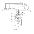
- a system comprising a centrifugal separator 1 for separating a liquid mixture of components, such as fuel oil contaminated with water and catalyst fines.
- the centrifugal separator comprises a rotor 2 supported by a spindle 4 which is rotatably arranged in a frame 3 around an axis of rotation (x).
- the separator comprises a drive motor 5, which may be arranged to drive the spindle in direct connection as shown or indirectly via a transmission such as belts or gears.
- the rotor forms within itself a separation chamber 6 wherein a stack of frustoconical separation discs 7 is arranged.
- An inlet 8 extends into the separation space for supply of the liquid mixture to be separated and a light phase outlet 9 for a separated light liquid component of the mixture (i.e. the purified oil) extends from the central portion of the separation chamber.
- a heavy phase outlet 10 for a separated heavy liquid component of the mixture extends from a portion of the separation chamber situated radially outside the central light phase outlet.
- a sludge space is formed as a radially outer portion of the separation chamber.
- the rotor is provided with a discharge mechanism comprising sludge discharge ports 11 extending from the sludge space for intermittent discharge of the sludge phase (e.g. larger solid particles such as catalyst fines) from the separation chamber.
- the inlet 9 of the centrifugal separator is connected to a supply line 12 for an inlet stream of fuel oil to be separated.
- a temperature conditioning unit 13 includes means to measure the temperature of the oil in the supply line and a heater for heating the oil.
- a dosing unit 14 for a separation aid is connected to the inlet 9 of the centrifugal separator.
- a flow regulating unit 18 is arranged to control (i.e. means to measure and/or regulate) the flow rate of oil in the supply line.
- the light phase outlet 9 of the centrifugal separator is connected to a delivery line 15 for delivery of a stream of purified fuel oil to the engine.
- the system further comprises an NMR apparatus 16 arranged to obtain a small sample stream of fuel oil from the delivery line.
- the NMR apparatus is further described below.
- the system includes a control unit 17 arranged to receive data from the NMR apparatus and to communicate with the temperature conditioning unit 13, the dosing unit 14 and the flow regulating unit 18.
- a stream of fuel oil to be purified is supplied to the inlet 8 of the centrifugal separator via the supply line 12.
- a predetermined amount of separation aid is added to and dispersed (i.e. finely divided) in and mixed with the stream of oil by the dosing unit 14.
- the dosing unit is arranged such that the oil and separation aid mixture is allowed to interact for a period of time before centrifugation in order to increase the extraction of catalyst fines from the oil into the separation aid.
- the stream of oil and separation aid thereafter enters into the separation chamber 6 of the centrifugal rotor 2 rotating at high speed.
- the stream of oil is accelerated into rotation and is introduced into the stack of separation discs 7 where it under the influence of centrifugal forces is separated into a light liquid component mainly comprising the purified oil, a heavy liquid component comprising water, any added separation aid and smaller catalyst fines and a sludge component comprising larger and denser particles (e.g. catalyst fines, sand, wear particles etc.).
- the light liquid component is transported towards the centre of the separation space where it is discharged through the light phase outlet 9.
- the heavy liquid component is transported radially outwards in the separation chamber and discharged over the top disc and through the heavy phase outlet 10.
- the sludge component is collected in the sludge space and discharged intermittently to a space outside the rotor by means of the discharge mechanism.
- a small sample stream of oil is diverted and introduced to the NMR apparatus 16.
- An example of an NMR apparatus is disclosed in US 2012/0001636 A1 .
- the sample stream is entered into a region of uniform magnetic field.
- a wire coil and electronic circuits are provided to both apply radio-frequency (RF) pulses to the sample (transmit) and to detect RF signals from the sample (receive).
- RF radio-frequency
- the operating frequency is defined by the nuclei concerned and the magnitude of the main field.
- the atomic nuclei under study in the sample are first allowed to polarize in the magnetic field.
- one or more RF pulses are applied to the sample with frequencies at or near the resonance frequency at which the nuclei freely precess in the applied uniform magnetic field.
- the transmit pulses have the effect of tilting the nucleus polarization relative to the direction of the applied field.
- the nuclei precess and create a time-varying magnetic field in the coil.
- the time-varying field induces a signal voltage in the coil which may be amplified and recorded.
- 29 Si and/or 2 Al nuclei spectra are obtained from the sample by NMR spectroscopy. From these spectra, the total levels of Al and Si in the oil stream can be identified.
- the zeolites used as catalyst fines typically contain 20-35 % of Si and 20-10 % Al.
- Examples of zeolites are ZSM-5 disclosed in US 3702886 and US 4067724 , ZSM-11 disclosed in US 3709979 , ZSM-12 disclosed in US 3832449 , ZSM-23 disclosed in US 4076842 , ZSM-35 disclosed in US 4016245 , ZSM-38 disclosed in US 4046859 and ZSM-48 disclosed in EP 15132 .
- the levels of one of the elements Al and Si and thus the total level of the two elements may alternatively be estimated if the level of the other element is known from the measurements.
- the control unit is arranged to adjust at least one parameter of the separation process in the centrifugal separator such as to increase the separation performance.
- the control unit verifies with the temperature conditioning unit 13 that the separation process is performed at the defined optimal temperature, such as 98°C.
- the flow regulating unit is instructed to decrease the flow rate of the oil in the supply line.
- the amount of separation aid from the dosing unit is increased to increase the separation performance.
- the separation aid such as water or polyethylene glycol
- the separation aid is added to the oil stream by the dosing unit, it is preferably dispersed in small droplets in the oil stream.
- the total area of the interface surface between the separation aid and the oil is increased.
- catalyst fines particles in the oil come in contact with the separation aid, they are extracted from the oil and into the separation aid.
- the fine droplets of separation aid, water from the oil stream and smaller catalyst fines coalesce into larger drops and eventually forms a liquid phase which is denser than the oil (heavy phase).
- the heavy phase including smaller catalyst fines is discharged through the heavy phase outlet as previously described.
Landscapes
- Chemical & Material Sciences (AREA)
- Oil, Petroleum & Natural Gas (AREA)
- Engineering & Computer Science (AREA)
- Chemical Kinetics & Catalysis (AREA)
- General Chemical & Material Sciences (AREA)
- Organic Chemistry (AREA)
- Physics & Mathematics (AREA)
- High Energy & Nuclear Physics (AREA)
- Analytical Chemistry (AREA)
- Life Sciences & Earth Sciences (AREA)
- Health & Medical Sciences (AREA)
- Biochemistry (AREA)
- General Health & Medical Sciences (AREA)
- General Physics & Mathematics (AREA)
- Immunology (AREA)
- Pathology (AREA)
- Combustion & Propulsion (AREA)
- Inorganic Chemistry (AREA)
- Production Of Liquid Hydrocarbon Mixture For Refining Petroleum (AREA)
- Catalysts (AREA)
Priority Applications (9)
| Application Number | Priority Date | Filing Date | Title |
|---|---|---|---|
| DK12173950.2T DK2679657T3 (en) | 2012-06-27 | 2012-06-27 | A method of separating FINE CATALYST material from an oil stream |
| EP12173950.2A EP2679657B1 (de) | 2012-06-27 | 2012-06-27 | Verfahren zum abscheiden von katalysatorfeinteilen aus einem ölstrom |
| EP13729729.7A EP2867341A1 (de) | 2012-06-27 | 2013-06-19 | Verfahren und system zur abscheidung von katalysatorfeinteilen aus einem ölstrom |
| US14/408,806 US20150191660A1 (en) | 2012-06-27 | 2013-06-19 | Method and system for separating catalyst fines from an oil stream |
| RU2015102270A RU2621731C2 (ru) | 2012-06-27 | 2013-06-19 | Способ для отделения катализаторной пыли от потока топливного масла |
| CN201380033410.XA CN104379706B (zh) | 2012-06-27 | 2013-06-19 | 用于从油物流中分离催化剂细末的方法和系统 |
| KR1020157001737A KR101700541B1 (ko) | 2012-06-27 | 2013-06-19 | 오일 스트림으로부터 촉매 미분체를 분리하는 방법 및 시스템 |
| PCT/EP2013/062706 WO2014001168A1 (en) | 2012-06-27 | 2013-06-19 | A method and system for separating catalyst fines from an oil stream |
| JP2015518980A JP5965062B2 (ja) | 2012-06-27 | 2013-06-19 | 油流から触媒微粒子を分離するための方法およびシステム |
Applications Claiming Priority (1)
| Application Number | Priority Date | Filing Date | Title |
|---|---|---|---|
| EP12173950.2A EP2679657B1 (de) | 2012-06-27 | 2012-06-27 | Verfahren zum abscheiden von katalysatorfeinteilen aus einem ölstrom |
Publications (2)
| Publication Number | Publication Date |
|---|---|
| EP2679657A1 true EP2679657A1 (de) | 2014-01-01 |
| EP2679657B1 EP2679657B1 (de) | 2016-01-06 |
Family
ID=48652084
Family Applications (2)
| Application Number | Title | Priority Date | Filing Date |
|---|---|---|---|
| EP12173950.2A Active EP2679657B1 (de) | 2012-06-27 | 2012-06-27 | Verfahren zum abscheiden von katalysatorfeinteilen aus einem ölstrom |
| EP13729729.7A Withdrawn EP2867341A1 (de) | 2012-06-27 | 2013-06-19 | Verfahren und system zur abscheidung von katalysatorfeinteilen aus einem ölstrom |
Family Applications After (1)
| Application Number | Title | Priority Date | Filing Date |
|---|---|---|---|
| EP13729729.7A Withdrawn EP2867341A1 (de) | 2012-06-27 | 2013-06-19 | Verfahren und system zur abscheidung von katalysatorfeinteilen aus einem ölstrom |
Country Status (8)
| Country | Link |
|---|---|
| US (1) | US20150191660A1 (de) |
| EP (2) | EP2679657B1 (de) |
| JP (1) | JP5965062B2 (de) |
| KR (1) | KR101700541B1 (de) |
| CN (1) | CN104379706B (de) |
| DK (1) | DK2679657T3 (de) |
| RU (1) | RU2621731C2 (de) |
| WO (1) | WO2014001168A1 (de) |
Cited By (4)
| Publication number | Priority date | Publication date | Assignee | Title |
|---|---|---|---|---|
| EP3421573A1 (de) * | 2017-06-28 | 2019-01-02 | Alfa Laval Corporate AB | Kraftstoffbehandlungssystem für einen motor und verfahren zur behandlung einer heizöl unter verwendung von dem system |
| EP3207971B1 (de) * | 2016-02-18 | 2020-03-25 | Alfa Laval Corporate AB | Verfahren und system zur reinigung von öligen abfällen |
| KR20200141087A (ko) * | 2018-05-18 | 2020-12-17 | 잇판샤단호징 에이치아이비디 겡큐쇼 | 바이오제트 연료의 제조 방법 |
| GR1010191B (el) * | 2020-12-30 | 2022-03-17 | Ευαγγελος Γεωργιου Δουσης | Συστημα επεξεργασιας πυθμενα μοναδας καταλυτικης πυρολυσης με φυγοκεντρικο διαχωριστηρα |
Families Citing this family (9)
| Publication number | Priority date | Publication date | Assignee | Title |
|---|---|---|---|---|
| EP3121595B1 (de) | 2015-07-22 | 2017-12-06 | CM Technologies GmbH | Verfahren zur ermittlung des gehalts an catalyst fines in einer probe eines schweröls |
| GB201515921D0 (en) * | 2015-09-08 | 2015-10-21 | Parker Hannifin Mfg Uk Ltd | Method |
| DK3290093T3 (da) * | 2016-09-06 | 2022-07-11 | Alfa Laval Corp Ab | Fremgangsmåde til oprensning af brændselsolie til en dieselmotor |
| GB201720276D0 (en) | 2017-12-05 | 2018-01-17 | Parker Hunnifin Emea S A R L | Detecting particles in a particle containing fluid |
| EP3533522B1 (de) | 2018-02-28 | 2026-04-29 | Alfa Laval Corporate AB | Zentrifugalabscheider und verfahren zum betrieb eines zentrifugalabscheiders |
| MX2022009296A (es) * | 2020-01-31 | 2022-08-15 | Dow Global Technologies Llc | Proceso de separacion de catalizadores. |
| US11879100B2 (en) | 2022-04-28 | 2024-01-23 | Baker Hughes Oilfield Operations Llc | Removing catalyst fines from heavy oils |
| EP4428215A1 (de) * | 2023-03-09 | 2024-09-11 | Alfa Laval Corporate AB | Verfahren zum betreiben eines systems mit einem zentrifugalabscheider |
| DE102023106308A1 (de) * | 2023-03-14 | 2024-09-19 | Gea Westfalia Separator Group Gmbh | Vollmantel-Schneckenzentrifuge und Verfahren zur Steuerung oder Regelung eines Trennprozesses mit der Vollmantel-Schneckenzentrifuge |
Citations (16)
| Publication number | Priority date | Publication date | Assignee | Title |
|---|---|---|---|---|
| US3255104A (en) * | 1962-07-05 | 1966-06-07 | Phillips Petroleum Co | Conditioning of crude oil charge to centrifuge for asphalt improvement |
| US3388054A (en) * | 1962-07-09 | 1968-06-11 | Pennsalt Chemicals Corp | Centrifugal separation of a solids-liquid mixture |
| US3702886A (en) | 1969-10-10 | 1972-11-14 | Mobil Oil Corp | Crystalline zeolite zsm-5 and method of preparing the same |
| US3709979A (en) | 1970-04-23 | 1973-01-09 | Mobil Oil Corp | Crystalline zeolite zsm-11 |
| US3832449A (en) | 1971-03-18 | 1974-08-27 | Mobil Oil Corp | Crystalline zeolite zsm{14 12 |
| US4016245A (en) | 1973-09-04 | 1977-04-05 | Mobil Oil Corporation | Crystalline zeolite and method of preparing same |
| US4046859A (en) | 1974-11-29 | 1977-09-06 | Mobil Oil Corporation | Crystalline zeolite and method of preparing same |
| US4067724A (en) | 1975-09-13 | 1978-01-10 | Bayer Aktiengesellschaft | N-(1,2,4-Triazin-5-on-4-yl)-glycines and herbicidal compositions |
| US4076842A (en) | 1975-06-10 | 1978-02-28 | Mobil Oil Corporation | Crystalline zeolite ZSM-23 and synthesis thereof |
| EP0015132A1 (de) | 1979-02-21 | 1980-09-03 | Mobil Oil Corporation | Kristalliner Zeolith, dessen Aufbau und Verwendung |
| US5976357A (en) * | 1993-11-29 | 1999-11-02 | Alfa Laval Separation Ab | Purification of oil |
| US20060217254A1 (en) * | 2002-12-12 | 2006-09-28 | Alfa Laval Corporate Ab | Method of purifying contaminated oil from particles suspended in the oil in a centrifugal separator |
| US20090120836A1 (en) | 2007-07-10 | 2009-05-14 | Weber Larry J | FCC-CFE CAT FINE EXTRACTION: METHOD AND SYSTEM FOR EXTRACTING CATALYST FINES FROM SLURRY OIL CAT FINE BOTTOMS (SOCFBs) INTO AN AQUEOUS LAYER |
| US20100023275A1 (en) * | 2008-07-28 | 2010-01-28 | Trygstad W Marcus | System and Method for Alkylation Process Analysis |
| US20120001636A1 (en) | 2010-06-29 | 2012-01-05 | Price John C | Capillary cartridge for miniaturized nuclear magnetic resonance (nmr) devices |
| WO2013087077A1 (en) | 2011-12-12 | 2013-06-20 | Nanonord A/S | A method of determining catalytic fines in an oil |
Family Cites Families (3)
| Publication number | Priority date | Publication date | Assignee | Title |
|---|---|---|---|---|
| JPS61125412A (ja) * | 1984-11-20 | 1986-06-13 | Nippon Oil & Fats Co Ltd | 触媒沈降促進剤 |
| CN1136294C (zh) * | 1999-12-01 | 2004-01-28 | 中国石油化工集团公司 | 一种脱除催化裂化油浆中催化剂粉末的方法 |
| US20060000787A1 (en) * | 2004-07-02 | 2006-01-05 | Galasso Louis Iii | Purification of impure oil by centrifugation |
-
2012
- 2012-06-27 EP EP12173950.2A patent/EP2679657B1/de active Active
- 2012-06-27 DK DK12173950.2T patent/DK2679657T3/en active
-
2013
- 2013-06-19 EP EP13729729.7A patent/EP2867341A1/de not_active Withdrawn
- 2013-06-19 KR KR1020157001737A patent/KR101700541B1/ko active Active
- 2013-06-19 WO PCT/EP2013/062706 patent/WO2014001168A1/en not_active Ceased
- 2013-06-19 US US14/408,806 patent/US20150191660A1/en not_active Abandoned
- 2013-06-19 JP JP2015518980A patent/JP5965062B2/ja active Active
- 2013-06-19 CN CN201380033410.XA patent/CN104379706B/zh active Active
- 2013-06-19 RU RU2015102270A patent/RU2621731C2/ru active
Patent Citations (18)
| Publication number | Priority date | Publication date | Assignee | Title |
|---|---|---|---|---|
| US3255104A (en) * | 1962-07-05 | 1966-06-07 | Phillips Petroleum Co | Conditioning of crude oil charge to centrifuge for asphalt improvement |
| US3388054A (en) * | 1962-07-09 | 1968-06-11 | Pennsalt Chemicals Corp | Centrifugal separation of a solids-liquid mixture |
| US3702886A (en) | 1969-10-10 | 1972-11-14 | Mobil Oil Corp | Crystalline zeolite zsm-5 and method of preparing the same |
| US3709979A (en) | 1970-04-23 | 1973-01-09 | Mobil Oil Corp | Crystalline zeolite zsm-11 |
| US3832449A (en) | 1971-03-18 | 1974-08-27 | Mobil Oil Corp | Crystalline zeolite zsm{14 12 |
| US4016245A (en) | 1973-09-04 | 1977-04-05 | Mobil Oil Corporation | Crystalline zeolite and method of preparing same |
| US4046859A (en) | 1974-11-29 | 1977-09-06 | Mobil Oil Corporation | Crystalline zeolite and method of preparing same |
| US4076842A (en) | 1975-06-10 | 1978-02-28 | Mobil Oil Corporation | Crystalline zeolite ZSM-23 and synthesis thereof |
| US4067724A (en) | 1975-09-13 | 1978-01-10 | Bayer Aktiengesellschaft | N-(1,2,4-Triazin-5-on-4-yl)-glycines and herbicidal compositions |
| EP0015132A1 (de) | 1979-02-21 | 1980-09-03 | Mobil Oil Corporation | Kristalliner Zeolith, dessen Aufbau und Verwendung |
| US5976357A (en) * | 1993-11-29 | 1999-11-02 | Alfa Laval Separation Ab | Purification of oil |
| EP0731830B1 (de) | 1993-11-29 | 2003-04-02 | Alfa Laval Separation Ab | Ölreinigung |
| US20060217254A1 (en) * | 2002-12-12 | 2006-09-28 | Alfa Laval Corporate Ab | Method of purifying contaminated oil from particles suspended in the oil in a centrifugal separator |
| EP1570036B1 (de) | 2002-12-12 | 2009-08-05 | Alfa Laval Corporate AB | Verfahren zur reinigung von kontaminiertem öl durch abtrennung von in dem öl suspendierten teilchen in einem zentrifugalabscheider |
| US20090120836A1 (en) | 2007-07-10 | 2009-05-14 | Weber Larry J | FCC-CFE CAT FINE EXTRACTION: METHOD AND SYSTEM FOR EXTRACTING CATALYST FINES FROM SLURRY OIL CAT FINE BOTTOMS (SOCFBs) INTO AN AQUEOUS LAYER |
| US20100023275A1 (en) * | 2008-07-28 | 2010-01-28 | Trygstad W Marcus | System and Method for Alkylation Process Analysis |
| US20120001636A1 (en) | 2010-06-29 | 2012-01-05 | Price John C | Capillary cartridge for miniaturized nuclear magnetic resonance (nmr) devices |
| WO2013087077A1 (en) | 2011-12-12 | 2013-06-20 | Nanonord A/S | A method of determining catalytic fines in an oil |
Cited By (7)
| Publication number | Priority date | Publication date | Assignee | Title |
|---|---|---|---|---|
| EP3207971B1 (de) * | 2016-02-18 | 2020-03-25 | Alfa Laval Corporate AB | Verfahren und system zur reinigung von öligen abfällen |
| EP3421573A1 (de) * | 2017-06-28 | 2019-01-02 | Alfa Laval Corporate AB | Kraftstoffbehandlungssystem für einen motor und verfahren zur behandlung einer heizöl unter verwendung von dem system |
| WO2019002458A1 (en) * | 2017-06-28 | 2019-01-03 | Alfa Laval Corporate Ab | FUEL TREATMENT SYSTEM FOR AN ENGINE AND METHOD USING THE SYSTEM |
| KR20200022448A (ko) * | 2017-06-28 | 2020-03-03 | 알파 라발 코포레이트 에이비 | 엔진용 연료 처리 시스템 및 이 시스템을 사용하는 방법 |
| US10961467B2 (en) | 2017-06-28 | 2021-03-30 | Alfa Laval Corporate Ab | Fuel treatment system for an engine and a method using the system |
| KR20200141087A (ko) * | 2018-05-18 | 2020-12-17 | 잇판샤단호징 에이치아이비디 겡큐쇼 | 바이오제트 연료의 제조 방법 |
| GR1010191B (el) * | 2020-12-30 | 2022-03-17 | Ευαγγελος Γεωργιου Δουσης | Συστημα επεξεργασιας πυθμενα μοναδας καταλυτικης πυρολυσης με φυγοκεντρικο διαχωριστηρα |
Also Published As
| Publication number | Publication date |
|---|---|
| JP5965062B2 (ja) | 2016-08-03 |
| EP2679657B1 (de) | 2016-01-06 |
| CN104379706A (zh) | 2015-02-25 |
| RU2015102270A (ru) | 2016-08-20 |
| JP2015522677A (ja) | 2015-08-06 |
| US20150191660A1 (en) | 2015-07-09 |
| KR101700541B1 (ko) | 2017-01-26 |
| WO2014001168A1 (en) | 2014-01-03 |
| EP2867341A1 (de) | 2015-05-06 |
| KR20150034194A (ko) | 2015-04-02 |
| CN104379706B (zh) | 2016-05-25 |
| RU2621731C2 (ru) | 2017-06-07 |
| DK2679657T3 (en) | 2016-03-21 |
Similar Documents
| Publication | Publication Date | Title |
|---|---|---|
| EP2679657B1 (de) | Verfahren zum abscheiden von katalysatorfeinteilen aus einem ölstrom | |
| US9493712B2 (en) | Separator for desalting petroleum crude oils having rag layer withdrawal | |
| MX2014015027A (es) | Separador de petroleo / agua de alta velocidad electroestatico coalescente. | |
| JP6931097B2 (ja) | エンジンのための燃料処理システムおよびシステムを使用する方法 | |
| JP2016509075A5 (de) | ||
| JP2020186405A (ja) | ディーゼルエンジン用燃料油の浄化の方法 | |
| US11098254B2 (en) | Diluted bitumen product water reduction | |
| KR20190097195A (ko) | 액체 혼합물로부터의 오염물의 분리 | |
| US20150315477A1 (en) | Demulsifier injection system for froth treatment product quality enhancement | |
| CA2851192C (en) | Demulsifier injection system for froth treatment product quality enhancement | |
| CN108611112A (zh) | 煤焦油脱水的方法及系统 | |
| CA3089213C (en) | Diluted bitumen fine water droplets capture | |
| CN209052630U (zh) | 撬装式离心油水分离装置 |
Legal Events
| Date | Code | Title | Description |
|---|---|---|---|
| PUAI | Public reference made under article 153(3) epc to a published international application that has entered the european phase |
Free format text: ORIGINAL CODE: 0009012 |
|
| AK | Designated contracting states |
Kind code of ref document: A1 Designated state(s): AL AT BE BG CH CY CZ DE DK EE ES FI FR GB GR HR HU IE IS IT LI LT LU LV MC MK MT NL NO PL PT RO RS SE SI SK SM TR |
|
| AX | Request for extension of the european patent |
Extension state: BA ME |
|
| TPAC | Observations filed by third parties |
Free format text: ORIGINAL CODE: EPIDOSNTIPA |
|
| 17P | Request for examination filed |
Effective date: 20140311 |
|
| RBV | Designated contracting states (corrected) |
Designated state(s): AL AT BE BG CH CY CZ DE DK EE ES FI FR GB GR HR HU IE IS IT LI LT LU LV MC MK MT NL NO PL PT RO RS SE SI SK SM TR |
|
| 17Q | First examination report despatched |
Effective date: 20140819 |
|
| RIC1 | Information provided on ipc code assigned before grant |
Ipc: C10G 31/10 20060101AFI20150526BHEP Ipc: G01N 24/08 20060101ALI20150526BHEP Ipc: C10M 175/00 20060101ALI20150526BHEP Ipc: C10L 1/08 20060101ALI20150526BHEP |
|
| GRAP | Despatch of communication of intention to grant a patent |
Free format text: ORIGINAL CODE: EPIDOSNIGR1 |
|
| INTG | Intention to grant announced |
Effective date: 20150722 |
|
| GRAS | Grant fee paid |
Free format text: ORIGINAL CODE: EPIDOSNIGR3 |
|
| GRAA | (expected) grant |
Free format text: ORIGINAL CODE: 0009210 |
|
| AK | Designated contracting states |
Kind code of ref document: B1 Designated state(s): AL AT BE BG CH CY CZ DE DK EE ES FI FR GB GR HR HU IE IS IT LI LT LU LV MC MK MT NL NO PL PT RO RS SE SI SK SM TR |
|
| REG | Reference to a national code |
Ref country code: GB Ref legal event code: FG4D |
|
| REG | Reference to a national code |
Ref country code: CH Ref legal event code: EP |
|
| REG | Reference to a national code |
Ref country code: IE Ref legal event code: FG4D |
|
| REG | Reference to a national code |
Ref country code: AT Ref legal event code: REF Ref document number: 768872 Country of ref document: AT Kind code of ref document: T Effective date: 20160215 |
|
| REG | Reference to a national code |
Ref country code: DE Ref legal event code: R096 Ref document number: 602012013580 Country of ref document: DE |
|
| REG | Reference to a national code |
Ref country code: SE Ref legal event code: TRGR |
|
| REG | Reference to a national code |
Ref country code: DK Ref legal event code: T3 Effective date: 20160315 |
|
| REG | Reference to a national code |
Ref country code: NO Ref legal event code: T2 Effective date: 20160106 |
|
| REG | Reference to a national code |
Ref country code: LT Ref legal event code: MG4D |
|
| REG | Reference to a national code |
Ref country code: NL Ref legal event code: MP Effective date: 20160106 |
|
| REG | Reference to a national code |
Ref country code: AT Ref legal event code: MK05 Ref document number: 768872 Country of ref document: AT Kind code of ref document: T Effective date: 20160106 |
|
| PG25 | Lapsed in a contracting state [announced via postgrant information from national office to epo] |
Ref country code: NL Free format text: LAPSE BECAUSE OF FAILURE TO SUBMIT A TRANSLATION OF THE DESCRIPTION OR TO PAY THE FEE WITHIN THE PRESCRIBED TIME-LIMIT Effective date: 20160106 |
|
| PG25 | Lapsed in a contracting state [announced via postgrant information from national office to epo] |
Ref country code: ES Free format text: LAPSE BECAUSE OF FAILURE TO SUBMIT A TRANSLATION OF THE DESCRIPTION OR TO PAY THE FEE WITHIN THE PRESCRIBED TIME-LIMIT Effective date: 20160106 Ref country code: FI Free format text: LAPSE BECAUSE OF FAILURE TO SUBMIT A TRANSLATION OF THE DESCRIPTION OR TO PAY THE FEE WITHIN THE PRESCRIBED TIME-LIMIT Effective date: 20160106 Ref country code: IT Free format text: LAPSE BECAUSE OF FAILURE TO SUBMIT A TRANSLATION OF THE DESCRIPTION OR TO PAY THE FEE WITHIN THE PRESCRIBED TIME-LIMIT Effective date: 20160106 Ref country code: GR Free format text: LAPSE BECAUSE OF FAILURE TO SUBMIT A TRANSLATION OF THE DESCRIPTION OR TO PAY THE FEE WITHIN THE PRESCRIBED TIME-LIMIT Effective date: 20160407 Ref country code: HR Free format text: LAPSE BECAUSE OF FAILURE TO SUBMIT A TRANSLATION OF THE DESCRIPTION OR TO PAY THE FEE WITHIN THE PRESCRIBED TIME-LIMIT Effective date: 20160106 |
|
| PG25 | Lapsed in a contracting state [announced via postgrant information from national office to epo] |
Ref country code: AT Free format text: LAPSE BECAUSE OF FAILURE TO SUBMIT A TRANSLATION OF THE DESCRIPTION OR TO PAY THE FEE WITHIN THE PRESCRIBED TIME-LIMIT Effective date: 20160106 Ref country code: PL Free format text: LAPSE BECAUSE OF FAILURE TO SUBMIT A TRANSLATION OF THE DESCRIPTION OR TO PAY THE FEE WITHIN THE PRESCRIBED TIME-LIMIT Effective date: 20160106 Ref country code: LT Free format text: LAPSE BECAUSE OF FAILURE TO SUBMIT A TRANSLATION OF THE DESCRIPTION OR TO PAY THE FEE WITHIN THE PRESCRIBED TIME-LIMIT Effective date: 20160106 Ref country code: IS Free format text: LAPSE BECAUSE OF FAILURE TO SUBMIT A TRANSLATION OF THE DESCRIPTION OR TO PAY THE FEE WITHIN THE PRESCRIBED TIME-LIMIT Effective date: 20160506 Ref country code: PT Free format text: LAPSE BECAUSE OF FAILURE TO SUBMIT A TRANSLATION OF THE DESCRIPTION OR TO PAY THE FEE WITHIN THE PRESCRIBED TIME-LIMIT Effective date: 20160506 Ref country code: RS Free format text: LAPSE BECAUSE OF FAILURE TO SUBMIT A TRANSLATION OF THE DESCRIPTION OR TO PAY THE FEE WITHIN THE PRESCRIBED TIME-LIMIT Effective date: 20160106 Ref country code: LV Free format text: LAPSE BECAUSE OF FAILURE TO SUBMIT A TRANSLATION OF THE DESCRIPTION OR TO PAY THE FEE WITHIN THE PRESCRIBED TIME-LIMIT Effective date: 20160106 |
|
| REG | Reference to a national code |
Ref country code: DE Ref legal event code: R097 Ref document number: 602012013580 Country of ref document: DE |
|
| PG25 | Lapsed in a contracting state [announced via postgrant information from national office to epo] |
Ref country code: EE Free format text: LAPSE BECAUSE OF FAILURE TO SUBMIT A TRANSLATION OF THE DESCRIPTION OR TO PAY THE FEE WITHIN THE PRESCRIBED TIME-LIMIT Effective date: 20160106 |
|
| PLBE | No opposition filed within time limit |
Free format text: ORIGINAL CODE: 0009261 |
|
| STAA | Information on the status of an ep patent application or granted ep patent |
Free format text: STATUS: NO OPPOSITION FILED WITHIN TIME LIMIT |
|
| PG25 | Lapsed in a contracting state [announced via postgrant information from national office to epo] |
Ref country code: SM Free format text: LAPSE BECAUSE OF FAILURE TO SUBMIT A TRANSLATION OF THE DESCRIPTION OR TO PAY THE FEE WITHIN THE PRESCRIBED TIME-LIMIT Effective date: 20160106 Ref country code: CZ Free format text: LAPSE BECAUSE OF FAILURE TO SUBMIT A TRANSLATION OF THE DESCRIPTION OR TO PAY THE FEE WITHIN THE PRESCRIBED TIME-LIMIT Effective date: 20160106 Ref country code: SK Free format text: LAPSE BECAUSE OF FAILURE TO SUBMIT A TRANSLATION OF THE DESCRIPTION OR TO PAY THE FEE WITHIN THE PRESCRIBED TIME-LIMIT Effective date: 20160106 Ref country code: RO Free format text: LAPSE BECAUSE OF FAILURE TO SUBMIT A TRANSLATION OF THE DESCRIPTION OR TO PAY THE FEE WITHIN THE PRESCRIBED TIME-LIMIT Effective date: 20160106 |
|
| 26N | No opposition filed |
Effective date: 20161007 |
|
| PG25 | Lapsed in a contracting state [announced via postgrant information from national office to epo] |
Ref country code: BE Free format text: LAPSE BECAUSE OF FAILURE TO SUBMIT A TRANSLATION OF THE DESCRIPTION OR TO PAY THE FEE WITHIN THE PRESCRIBED TIME-LIMIT Effective date: 20160106 |
|
| PG25 | Lapsed in a contracting state [announced via postgrant information from national office to epo] |
Ref country code: MC Free format text: LAPSE BECAUSE OF FAILURE TO SUBMIT A TRANSLATION OF THE DESCRIPTION OR TO PAY THE FEE WITHIN THE PRESCRIBED TIME-LIMIT Effective date: 20160106 |
|
| REG | Reference to a national code |
Ref country code: CH Ref legal event code: PL |
|
| PG25 | Lapsed in a contracting state [announced via postgrant information from national office to epo] |
Ref country code: SI Free format text: LAPSE BECAUSE OF FAILURE TO SUBMIT A TRANSLATION OF THE DESCRIPTION OR TO PAY THE FEE WITHIN THE PRESCRIBED TIME-LIMIT Effective date: 20160106 Ref country code: BG Free format text: LAPSE BECAUSE OF FAILURE TO SUBMIT A TRANSLATION OF THE DESCRIPTION OR TO PAY THE FEE WITHIN THE PRESCRIBED TIME-LIMIT Effective date: 20160406 |
|
| REG | Reference to a national code |
Ref country code: IE Ref legal event code: MM4A |
|
| REG | Reference to a national code |
Ref country code: FR Ref legal event code: ST Effective date: 20170228 |
|
| PG25 | Lapsed in a contracting state [announced via postgrant information from national office to epo] |
Ref country code: LI Free format text: LAPSE BECAUSE OF NON-PAYMENT OF DUE FEES Effective date: 20160630 Ref country code: CH Free format text: LAPSE BECAUSE OF NON-PAYMENT OF DUE FEES Effective date: 20160630 Ref country code: FR Free format text: LAPSE BECAUSE OF NON-PAYMENT OF DUE FEES Effective date: 20160630 |
|
| PG25 | Lapsed in a contracting state [announced via postgrant information from national office to epo] |
Ref country code: IE Free format text: LAPSE BECAUSE OF NON-PAYMENT OF DUE FEES Effective date: 20160627 |
|
| PG25 | Lapsed in a contracting state [announced via postgrant information from national office to epo] |
Ref country code: HU Free format text: LAPSE BECAUSE OF FAILURE TO SUBMIT A TRANSLATION OF THE DESCRIPTION OR TO PAY THE FEE WITHIN THE PRESCRIBED TIME-LIMIT; INVALID AB INITIO Effective date: 20120627 Ref country code: CY Free format text: LAPSE BECAUSE OF FAILURE TO SUBMIT A TRANSLATION OF THE DESCRIPTION OR TO PAY THE FEE WITHIN THE PRESCRIBED TIME-LIMIT Effective date: 20160106 |
|
| PG25 | Lapsed in a contracting state [announced via postgrant information from national office to epo] |
Ref country code: MT Free format text: LAPSE BECAUSE OF NON-PAYMENT OF DUE FEES Effective date: 20160630 Ref country code: MK Free format text: LAPSE BECAUSE OF FAILURE TO SUBMIT A TRANSLATION OF THE DESCRIPTION OR TO PAY THE FEE WITHIN THE PRESCRIBED TIME-LIMIT Effective date: 20160106 Ref country code: LU Free format text: LAPSE BECAUSE OF NON-PAYMENT OF DUE FEES Effective date: 20160627 Ref country code: TR Free format text: LAPSE BECAUSE OF FAILURE TO SUBMIT A TRANSLATION OF THE DESCRIPTION OR TO PAY THE FEE WITHIN THE PRESCRIBED TIME-LIMIT Effective date: 20160106 |
|
| PG25 | Lapsed in a contracting state [announced via postgrant information from national office to epo] |
Ref country code: AL Free format text: LAPSE BECAUSE OF FAILURE TO SUBMIT A TRANSLATION OF THE DESCRIPTION OR TO PAY THE FEE WITHIN THE PRESCRIBED TIME-LIMIT Effective date: 20160106 |
|
| P01 | Opt-out of the competence of the unified patent court (upc) registered |
Effective date: 20230418 |
|
| PGFP | Annual fee paid to national office [announced via postgrant information from national office to epo] |
Ref country code: GB Payment date: 20240509 Year of fee payment: 13 |
|
| PGFP | Annual fee paid to national office [announced via postgrant information from national office to epo] |
Ref country code: DK Payment date: 20240612 Year of fee payment: 13 |
|
| PGFP | Annual fee paid to national office [announced via postgrant information from national office to epo] |
Ref country code: NO Payment date: 20240611 Year of fee payment: 13 |
|
| PGFP | Annual fee paid to national office [announced via postgrant information from national office to epo] |
Ref country code: SE Payment date: 20240510 Year of fee payment: 13 |
|
| PGFP | Annual fee paid to national office [announced via postgrant information from national office to epo] |
Ref country code: DE Payment date: 20250402 Year of fee payment: 14 |
|
| REG | Reference to a national code |
Ref country code: DK Ref legal event code: EBP Effective date: 20250630 |
|
| REG | Reference to a national code |
Ref country code: SE Ref legal event code: EUG |
|
| GBPC | Gb: european patent ceased through non-payment of renewal fee |
Effective date: 20250627 |
|
| PG25 | Lapsed in a contracting state [announced via postgrant information from national office to epo] |
Ref country code: GB Free format text: LAPSE BECAUSE OF NON-PAYMENT OF DUE FEES Effective date: 20250627 |
|
| PG25 | Lapsed in a contracting state [announced via postgrant information from national office to epo] |
Ref country code: NO Free format text: LAPSE BECAUSE OF NON-PAYMENT OF DUE FEES Effective date: 20250630 |