EP2679731A2 - Energiespeicherung, die als Maschinengegengewicht integriert ist - Google Patents
Energiespeicherung, die als Maschinengegengewicht integriert ist Download PDFInfo
- Publication number
- EP2679731A2 EP2679731A2 EP13002967.1A EP13002967A EP2679731A2 EP 2679731 A2 EP2679731 A2 EP 2679731A2 EP 13002967 A EP13002967 A EP 13002967A EP 2679731 A2 EP2679731 A2 EP 2679731A2
- Authority
- EP
- European Patent Office
- Prior art keywords
- machine
- energy storage
- implement
- storage system
- frame
- Prior art date
- Legal status (The legal status is an assumption and is not a legal conclusion. Google has not performed a legal analysis and makes no representation as to the accuracy of the status listed.)
- Withdrawn
Links
- 238000004146 energy storage Methods 0.000 title claims abstract description 38
- 238000011084 recovery Methods 0.000 claims abstract description 18
- 239000000446 fuel Substances 0.000 claims abstract description 9
- 239000003990 capacitor Substances 0.000 claims abstract description 5
- 230000005484 gravity Effects 0.000 claims description 12
- 238000005381 potential energy Methods 0.000 claims description 7
- 230000000153 supplemental effect Effects 0.000 description 4
- 238000000034 method Methods 0.000 description 3
- 239000000126 substance Substances 0.000 description 2
- 230000004075 alteration Effects 0.000 description 1
- 230000005540 biological transmission Effects 0.000 description 1
- 230000001680 brushing effect Effects 0.000 description 1
- 238000002485 combustion reaction Methods 0.000 description 1
- 238000010276 construction Methods 0.000 description 1
- 230000008878 coupling Effects 0.000 description 1
- 238000010168 coupling process Methods 0.000 description 1
- 238000005859 coupling reaction Methods 0.000 description 1
- 238000009313 farming Methods 0.000 description 1
- 239000012530 fluid Substances 0.000 description 1
- 238000010348 incorporation Methods 0.000 description 1
- 238000012423 maintenance Methods 0.000 description 1
- 239000000463 material Substances 0.000 description 1
- 238000005065 mining Methods 0.000 description 1
- 238000012986 modification Methods 0.000 description 1
- 230000004048 modification Effects 0.000 description 1
- 230000008450 motivation Effects 0.000 description 1
- 238000004806 packaging method and process Methods 0.000 description 1
- 210000003813 thumb Anatomy 0.000 description 1
Images

Classifications
-
- E—FIXED CONSTRUCTIONS
- E02—HYDRAULIC ENGINEERING; FOUNDATIONS; SOIL SHIFTING
- E02F—DREDGING; SOIL-SHIFTING
- E02F9/00—Component parts of dredgers or soil-shifting machines, not restricted to one of the kinds covered by groups E02F3/00 - E02F7/00
- E02F9/08—Superstructures; Supports for superstructures
- E02F9/0858—Arrangement of component parts installed on superstructures not otherwise provided for, e.g. electric components, fenders, air-conditioning units
-
- B—PERFORMING OPERATIONS; TRANSPORTING
- B66—HOISTING; LIFTING; HAULING
- B66F—HOISTING, LIFTING, HAULING OR PUSHING, NOT OTHERWISE PROVIDED FOR, e.g. DEVICES WHICH APPLY A LIFTING OR PUSHING FORCE DIRECTLY TO THE SURFACE OF A LOAD
- B66F9/00—Devices for lifting or lowering bulky or heavy goods for loading or unloading purposes
- B66F9/06—Devices for lifting or lowering bulky or heavy goods for loading or unloading purposes movable, with their loads, on wheels or the like, e.g. fork-lift trucks
- B66F9/075—Constructional features or details
- B66F9/07554—Counterweights
-
- E—FIXED CONSTRUCTIONS
- E02—HYDRAULIC ENGINEERING; FOUNDATIONS; SOIL SHIFTING
- E02F—DREDGING; SOIL-SHIFTING
- E02F9/00—Component parts of dredgers or soil-shifting machines, not restricted to one of the kinds covered by groups E02F3/00 - E02F7/00
- E02F9/18—Counterweights
Definitions
- This patent disclosure relates generally to machines including hybrid arrangements for energy recovery, and, more particularly to energy storage components of a hybrid arrangement for a machine.
- Hybrid powertrain systems may recover or recycle energy that would otherwise be lost during operation, and store the potential energy for later use.
- the energy storage systems for such hybrid powertrain systems may add significant weight to the machine and require a relatively large amount of space within the machine.
- bulky energy systems may result in significant alterations of the machine's center of gravity.
- the utilization of such hybrid powertrain systems in machines often presents packaging challenges when attempting to incorporate them into machine designs.
- Hybrid powertrain systems may be particularly attractive for use in off-highway machines, which often include hydraulic systems for either or both of the movement of attached implements, or motivation of the machine.
- the machines often include energy recovery systems to recover or recycle the energy associated, for example, with releasing the implement from the elevated position, or arresting movement of machine.
- the incorporation of the energy storage systems for such hybrid powertrain systems into off-highway machines may be particularly challenging inasmuch as weight distribution may affect not only operation, but also wear of various components of the machine.
- manufacturers often seek to place components of the energy storage systems at or near the center of gravity of the machine in order to minimize the impact on weight distribution.
- Energy storage systems located at or near the center of gravity of the machine may occupy what is generally considered valuable space under the hood of the machine, potentially undesirably increasing the size of at least portions of the machine.
- the disclosure describes, in one aspect, a machine having a frame, at least one implement, and a linkage assembly movably coupled to the implement and to the frame.
- the machine also includes an energy recovery system that includes an energy storage system.
- the energy storage system includes at least one of a hydraulic accumulator, a battery, a flywheel, an ultra-capacitor, a fuel cell, and an auxiliary power unit. At least a portion of the energy storage system is disposed as counterweight to the implement.
- the disclosure describes, in another aspect, a moveable machine having a frame supported on a plurality of motivators, and at least one implement movably coupled to the frame by a linkage assembly.
- the machine also includes an energy recovery system adapted to recover and store potential energy.
- the energy recovery system includes an energy storage system having at least one of a hydraulic accumulator, a battery, a flywheel, an ultra-capacitor, a fuel cell, and an auxiliary power unit. At least a portion of the energy storage system is disposed as counterweight to the implement.
- the disclosure describes, in yet another aspect, a machine having a frame having at least one implement coupled by way of a linkage assembly substantially at a first end of the frame.
- the machine also includes an energy recovery system having an energy storage system.
- the energy storage system has a center or gravity and includes at least one of a hydraulic accumulator, a battery, a flywheel, an ultra-capacitor, a fuel cell, and an auxiliary power unit.
- the energy storage system is disposed along the frame to have its center of gravity other than coincident with a center of gravity of the machine, and at least a portion of the energy storage system disposed substantially along a second end of the frame as counterweight to the implement.
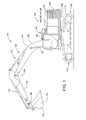
- This disclosure relates to a counterweight arrangement for a machine 100, such as an excavator 102 illustrated in FIG. 1 , that includes an attachment 104.
- the illustrated excavator 102 includes a frame 106 that is swingably supported on an undercarriage 108 that includes a plurality of motivators 110.
- the motivators 110 include a pair of rotatably mounted tracks 112 along either side of the undercarriage 108.
- Alternate embodiments may include, for example, wheels (not illustrated).
- the attachment 104 includes a linkage 114 which couples an implement 116, here, a bucket 118, to the frame 106.
- the linkage 114 includes a boom 120 that is pivotably supported on the frame 106, and a stick 122 pivotably coupled to the boom 120, the implement 116 being pivotably coupled to the stick 122.
- the implement 116 is illustrated as a bucket 118, the implement 116 may alternatively be, for example, a compactor, a grapple, a multi-processor, thumbs, a rake, a ripper, or shears.
- Movement of the boom 120, stick 122, and implement 116 is controlled by a number of actuators 126, 128, 130.
- the boom 120 is pivotably coupled to frame 106 at one end 132.
- the pair of actuators 126 is provided, only one being visible in the FIG. 1 .
- the actuators 126 are disposed on either side of the boom 120, coupled at one end to the frame 106, and at the other end to the boom 120.
- the stick 122 is pivotably coupled to the boom 120 at a pivot connection 134; movement of the stick 122 relative to the boom 120 is controlled by the actuator 128.
- the implement 116 is pivotably coupled to the stick 122 at pivot connection 136; movement of the implement 116 relative to the stick 122 is controlled by actuator 130.
- the engine 140 may be of any appropriate type.
- the engine 140 may be an internal combustion engine or any type power source known to one skilled in the art now or in the future.
- the hydraulic system 142 may control operations of the machine 100, such as, for example, the swinging of the frame 106 relative to the undercarriage 108, or movement of the motivators 110 to propel the machine 100, and operation of the actuators 126, 128, 130, and, therefore, the movement of the boom 120, stick, 122, implement 116, and any supplemental load carried by or contained within implement 116.
- the term "load" 146 will be used to describe the implement 116, any supplemental load carried by or contained within the implement 116, and any linkage 114 extending from the frame 106 and coupling the implement to the frame 106.
- the load 146 would include the boom 120, stick 122, implement 116, and actuators 126, 128, 130, as well as any supplemental load, such as dirt, carried within the implement 116.
- the load may be the actuators, the implement and any supplemental load.
- the energy recovery system 144 may include a hybrid powertrain system 148 that is adapted to recover, store, and reuse potential energy that would otherwise be lost in the operation of the machine 100.
- the implement 116 may be raised to an elevated position. As the implement 116 may be relatively heavy, the implement 116 may gain potential energy when raised to the elevated position.
- the energy recovery system 144 may recover or recycle the energy associated with releasing the implement 116 from the elevated position.
- machine 100 such as the excavator 102 illustrated in FIG. 1
- the frame 106 when the frame 106 is rotated relative to the undercarriage 108, the frame 106 may gain potential energy.
- the energy recovery system 144 may likewise recover energy associated with arresting the swing of the frame 106 relative to the undercarriage 108.
- the hybrid powertrain system 148 recovers and stores this energy in an energy storage system 150 for later use.
- the hybrid powertrain system 148 then recycles this stored energy to power operations of the machine 100.
- the operation of the energy recovery system 144 including the hybrid power train system 148 is known and will be understood by those of skill in the art.
- the energy storage system 150 may include components that store energy in electrical, chemical, hydraulic, or mechanical form.
- the energy storage system 150 may include one or more components such as a flywheel, a battery, an ultracapacitor, a fuel cell, an auxiliary power unit, and one or more accumulators.
- At least a portion of the components of the energy storage system 150 are disposed as a counterweight to the load 146, including the implement 116 and linkage 114.
- the center of gravity of the frame 106 is typically disposed coincident with the axis of rotation of the frame 106 relative to the undercarriage 108.
- at least a portion of the energy storage system 150 is disposed to act as a counterweight to the load 146 of the implement 116 and linkage 114.
- the energy storage system 150 is disposed relative to the frame 106 generally opposite the attachment of the linkage 114 and implement 116.
- the center of gravity of the energy storage system 150 is disposed other than coincident with the center of gravity of the machine 100, and, more particularly, the frame 106 and everything supported on the frame 106 in the illustrated excavator 102.
- the counterweight of the energy storage system 150 creates a moment opposite that created by the load 146 to negate at least a portion of the moment applied to the frame 106 from the linkage 114 and implement 116.
- the machine 100 may include additional counterweight 152, as illustrated in FIG. 1 .
- the wheel loader 202 includes an articulated frame 206 supported on a plurality of ground engaging devices 208 or motivators 210, here, a plurality of wheels 212.
- a cab or operator station 238 may be supported on the frame 206.
- a lift arm 220 is pivotably coupled to the frame 206 at one end, and to an implement 216, here, a bucket 218 at that other end.
- the wheel loader 202 includes a body 207 that may contain an engine 240, a transmission 241, a hydraulic system 242 and an energy recovery system 244 including a pump 243 and one or more valves 245.
- the energy recovery system 244 of the wheel loader 202 of FIG. 2 may include a hybrid powertrain system including an energy storage system 250.
- the energy storage system 250 may include components that store energy in electrical, chemical, hydraulic, or mechanical form.
- the energy storage system 250 may include one or more components such as a flywheel, a battery, an ultracapacitor, a fuel cell, an auxiliary power unit, and one or more accumulators.
- the energy storage system 250 may include one or more accumulators, and the valve 245 may control the flow of fluid from the energy recover system 244 to the accumulators.
- the energy storage system 250 is disposed as a counterweight to the lift arm 220 and implement 216.
- the machine 200 may include additional counterweight 252.
- the present disclosure is applicable to machines 100, 200 including a load 146, 220, 216 that extends from the machine 100, 200.
- the term "machine” may refer to any machine that requires the use of a counterweight to balance a load 146, 220, 216, such as machines that perform some type of operation associated with an industry such as mining, construction, farming, transportation, or any other industry known in the art.
- the machine 100, 200 may be an earth-moving machine, such as a tractor, material handler, a skid steer loader, or the like.
- one or more implements may be connected to the machine 100, 200.
- Such implements may be utilized for a variety of tasks, including, for example, brushing, compacting, grading, lifting, loading, plowing, ripping, and include, for example, augers, blades, breakers/hammers, brushes, buckets, compactors, cutters, forked lifting devices, grader bits and end bits, grapples, moldboards, rippers, scarifiers, shears, snow plows, snow wings, and others.
- the overall weight of the machine 100, 200 may be reduced inasmuch as the additional counterweight required may be minimized or eliminated entirely. Similarly, this reduction of counterweight may result in fuel savings or a reduction of the costs associated with the inclusion, placement, and maintenance of additional counterweight.
Landscapes
- Engineering & Computer Science (AREA)
- Structural Engineering (AREA)
- Civil Engineering (AREA)
- Mining & Mineral Resources (AREA)
- General Engineering & Computer Science (AREA)
- Transportation (AREA)
- Life Sciences & Earth Sciences (AREA)
- Geology (AREA)
- Mechanical Engineering (AREA)
- Operation Control Of Excavators (AREA)
- Arrangement Or Mounting Of Propulsion Units For Vehicles (AREA)
- Component Parts Of Construction Machinery (AREA)
- Hybrid Electric Vehicles (AREA)
- Electric Propulsion And Braking For Vehicles (AREA)
Applications Claiming Priority (1)
| Application Number | Priority Date | Filing Date | Title |
|---|---|---|---|
| US13/534,797 US20140000973A1 (en) | 2012-06-27 | 2012-06-27 | Energy Storage Integrated as Machine Counterweight |
Publications (1)
| Publication Number | Publication Date |
|---|---|
| EP2679731A2 true EP2679731A2 (de) | 2014-01-01 |
Family
ID=48747274
Family Applications (1)
| Application Number | Title | Priority Date | Filing Date |
|---|---|---|---|
| EP13002967.1A Withdrawn EP2679731A2 (de) | 2012-06-27 | 2013-06-10 | Energiespeicherung, die als Maschinengegengewicht integriert ist |
Country Status (3)
| Country | Link |
|---|---|
| US (1) | US20140000973A1 (de) |
| EP (1) | EP2679731A2 (de) |
| JP (1) | JP2014009589A (de) |
Cited By (6)
| Publication number | Priority date | Publication date | Assignee | Title |
|---|---|---|---|---|
| CN104196079A (zh) * | 2014-07-25 | 2014-12-10 | 昆山三一数字科技有限公司 | 一种液压挖掘机混合动力系统及其液压挖掘机 |
| CN105297800A (zh) * | 2014-07-28 | 2016-02-03 | 卡特彼勒公司 | 用于机器的机具系统的联动组件 |
| CN106840295A (zh) * | 2017-01-24 | 2017-06-13 | 徐州市产品质量监督检验中心 | 一种挖掘机燃油经济性智能检测系统和方法 |
| CN111094659A (zh) * | 2018-03-29 | 2020-05-01 | 株式会社日立建机Tierra | 液压挖掘机 |
| WO2021035475A1 (en) * | 2019-08-26 | 2021-03-04 | Guangxi Liugong Machinery Co., Ltd. | Loader |
| GB2615333A (en) * | 2022-02-03 | 2023-08-09 | Bamford Excavators Ltd | Working vehicle |
Families Citing this family (14)
| Publication number | Priority date | Publication date | Assignee | Title |
|---|---|---|---|---|
| WO2015005506A1 (ko) * | 2013-07-08 | 2015-01-15 | 볼보 컨스트럭션 이큅먼트 에이비 | 건설기계 |
| JP6164645B2 (ja) | 2013-09-18 | 2017-07-19 | キャタピラー エス エー アール エル | 作業機械におけるカウンタウエイト装置 |
| US20160107531A1 (en) * | 2015-12-29 | 2016-04-21 | Caterpillar Inc. | System for recovering electrical energy from machine |
| JP6560640B2 (ja) * | 2016-04-20 | 2019-08-14 | 株式会社日立建機ティエラ | 小型油圧ショベル |
| US10184227B2 (en) * | 2016-06-21 | 2019-01-22 | Kubota Corporation | Work machine |
| US11427450B2 (en) | 2018-06-01 | 2022-08-30 | Hyster-Yale Group, Inc. | Lift truck having advantageous design elements |
| KR102198830B1 (ko) * | 2019-04-05 | 2021-01-05 | 울산대학교 산학협력단 | 에너지 회생기능을 가지는 pem 연료전지 지게차 |
| CN110219332B (zh) * | 2019-05-12 | 2024-05-28 | 董志强 | 一种挖掘机的动臂机构重力抵消装置 |
| KR102470708B1 (ko) * | 2020-11-18 | 2022-11-28 | 에스퓨얼셀(주) | 연료전지 지게차 |
| US20240309607A1 (en) * | 2021-03-02 | 2024-09-19 | Jdc Corporation | Construction Machine |
| DE102021130374A1 (de) * | 2021-11-19 | 2023-05-25 | Liebherr-Werk Bischofshofen Gmbh | Arbeitsmaschine |
| DE202022100634U1 (de) | 2022-02-03 | 2023-05-05 | Liebherr-Werk Bischofshofen Gmbh | Arbeitsmaschine |
| CN121368661A (zh) | 2023-07-07 | 2026-01-20 | 神钢建机株式会社 | 工程机械 |
| WO2025013632A1 (ja) | 2023-07-07 | 2025-01-16 | コベルコ建機株式会社 | 作業機械 |
Family Cites Families (21)
| Publication number | Priority date | Publication date | Assignee | Title |
|---|---|---|---|---|
| GB975450A (en) * | 1962-06-26 | 1964-11-18 | Ransomes Sims & Jefferies Ltd | Improvements in or relating to fork lift trucks |
| US3367441A (en) * | 1966-04-01 | 1968-02-06 | Allis Chalmers Mfg Co | Unitized battery case and counterweight |
| US3497090A (en) * | 1968-04-03 | 1970-02-24 | Allis Chalmers Mfg Co | Combined battery case and counterweight |
| US4149733A (en) * | 1977-12-13 | 1979-04-17 | Caterpillar Tractor Co. | Fuel tanks and bumper for loader |
| SE422932B (sv) * | 1980-06-02 | 1982-04-05 | Atlas Copco Ab | Batteridriven lastmaskin med ett lyftorgan for batteripaket samt en fristaende stodpall for att uppbera batteripaketet |
| US4761954A (en) * | 1987-03-16 | 1988-08-09 | Dynamic Hydraulic Systems, Inc. | Fork-lift system |
| DE29804856U1 (de) * | 1998-03-18 | 1998-07-09 | Karl Schaeff GmbH & Co. Maschinenfabrik, 74595 Langenburg | Bagger, insbesondere Minibagger |
| JPH11343642A (ja) * | 1998-06-01 | 1999-12-14 | Kobe Steel Ltd | バッテリー駆動式作業機械 |
| US6901729B1 (en) * | 2004-03-31 | 2005-06-07 | Cnh America Llc | Header lift system with hydraulic counterweight |
| JP4544121B2 (ja) * | 2005-09-29 | 2010-09-15 | コベルコ建機株式会社 | 建設機械 |
| US7388301B2 (en) * | 2005-10-12 | 2008-06-17 | Kobelco Construction Machinery Co., Ltd. | Construction machine |
| US8100210B2 (en) * | 2006-02-07 | 2012-01-24 | Takeuchi Mfg. Co., Ltd | Electrically driven industrial vehicle |
| US7849951B2 (en) * | 2007-02-28 | 2010-12-14 | Crown Equipment Corporation | Materials handling vehicle having at least one controller coupled to a front wall of a frame |
| JP5338479B2 (ja) * | 2009-05-25 | 2013-11-13 | コベルコ建機株式会社 | ハイブリッド作業機械 |
| JP5163593B2 (ja) * | 2009-05-25 | 2013-03-13 | コベルコ建機株式会社 | ハイブリッド作業機械 |
| JP2010270555A (ja) * | 2009-05-25 | 2010-12-02 | Kobelco Contstruction Machinery Ltd | 作業機械の架台 |
| JP5113198B2 (ja) * | 2010-01-19 | 2013-01-09 | 日立建機株式会社 | 建設機械の冷却構造 |
| JP5172898B2 (ja) * | 2010-06-15 | 2013-03-27 | 日立建機株式会社 | 電動式建設機械 |
| JP5814577B2 (ja) * | 2011-03-24 | 2015-11-17 | 株式会社小松製作所 | 電動式作業車両及びそのバッテリ保持構造 |
| JP5814578B2 (ja) * | 2011-03-24 | 2015-11-17 | 株式会社小松製作所 | 電動式作業車両及びそのベースフレーム |
| JP5296826B2 (ja) * | 2011-03-30 | 2013-09-25 | 株式会社小松製作所 | 蓄電装置およびこれを備えた建設機械 |
-
2012
- 2012-06-27 US US13/534,797 patent/US20140000973A1/en not_active Abandoned
-
2013
- 2013-06-10 EP EP13002967.1A patent/EP2679731A2/de not_active Withdrawn
- 2013-06-26 JP JP2013134116A patent/JP2014009589A/ja active Pending
Non-Patent Citations (1)
| Title |
|---|
| None |
Cited By (8)
| Publication number | Priority date | Publication date | Assignee | Title |
|---|---|---|---|---|
| CN104196079A (zh) * | 2014-07-25 | 2014-12-10 | 昆山三一数字科技有限公司 | 一种液压挖掘机混合动力系统及其液压挖掘机 |
| CN105297800A (zh) * | 2014-07-28 | 2016-02-03 | 卡特彼勒公司 | 用于机器的机具系统的联动组件 |
| CN106840295A (zh) * | 2017-01-24 | 2017-06-13 | 徐州市产品质量监督检验中心 | 一种挖掘机燃油经济性智能检测系统和方法 |
| CN111094659A (zh) * | 2018-03-29 | 2020-05-01 | 株式会社日立建机Tierra | 液压挖掘机 |
| CN111094659B (zh) * | 2018-03-29 | 2021-09-24 | 株式会社日立建机Tierra | 液压挖掘机 |
| WO2021035475A1 (en) * | 2019-08-26 | 2021-03-04 | Guangxi Liugong Machinery Co., Ltd. | Loader |
| GB2615333A (en) * | 2022-02-03 | 2023-08-09 | Bamford Excavators Ltd | Working vehicle |
| EP4223939A3 (de) * | 2022-02-03 | 2023-10-04 | J.C. Bamford Excavators Limited | Wasserstoffbetriebenens arbeitsfahrzeug |
Also Published As
| Publication number | Publication date |
|---|---|
| JP2014009589A (ja) | 2014-01-20 |
| US20140000973A1 (en) | 2014-01-02 |
Similar Documents
| Publication | Publication Date | Title |
|---|---|---|
| EP2679731A2 (de) | Energiespeicherung, die als Maschinengegengewicht integriert ist | |
| EP2639360B1 (de) | Mobile Vorrichtung | |
| US7793740B2 (en) | Ride control for motor graders | |
| US9458842B2 (en) | Closed loop drive circuit with external brake assist | |
| US9051944B2 (en) | Hydraulic system and control logic for collection and recovery of energy in a double actuator arrangement | |
| US10711431B2 (en) | Clamp implement for excavator | |
| KR102657223B1 (ko) | 작업 기계용 하부 주행체 | |
| EP3433433B1 (de) | Radladerfronteinheit und radlader | |
| KR20160052390A (ko) | 작업용 기계 | |
| CN203531031U (zh) | 一种轮式机动破障车 | |
| US9303383B2 (en) | Lift arm cross member | |
| CN201258498Y (zh) | 挖掘装载机的工作装置 | |
| CN205575410U (zh) | 一种挖装机 | |
| US9267262B2 (en) | Lift arm linkage with extension cylinder | |
| CN103496657B (zh) | 一种轮式机动破障车 | |
| US20150345103A1 (en) | Linkage assembly for machine | |
| CN211113812U (zh) | 一种挖掘工程车 | |
| CN202265849U (zh) | 轮式挖掘装载机 | |
| JP3173436U (ja) | 作業用自動車のホイールローダーのブレードとバケットの機能結合型アタッチメント。 | |
| JP2017150246A (ja) | パワーショベル | |
| JP2012140834A (ja) | 作業機械 |
Legal Events
| Date | Code | Title | Description |
|---|---|---|---|
| PUAI | Public reference made under article 153(3) epc to a published international application that has entered the european phase |
Free format text: ORIGINAL CODE: 0009012 |
|
| AK | Designated contracting states |
Kind code of ref document: A2 Designated state(s): AL AT BE BG CH CY CZ DE DK EE ES FI FR GB GR HR HU IE IS IT LI LT LU LV MC MK MT NL NO PL PT RO RS SE SI SK SM TR |
|
| AX | Request for extension of the european patent |
Extension state: BA ME |
|
| 18D | Application deemed to be withdrawn |
Effective date: 20170103 |
|
| STAA | Information on the status of an ep patent application or granted ep patent |
Free format text: STATUS: THE APPLICATION IS DEEMED TO BE WITHDRAWN |