EP3095934B1 - Dispositif de detection d'une position de verrou - Google Patents
Dispositif de detection d'une position de verrou Download PDFInfo
- Publication number
- EP3095934B1 EP3095934B1 EP16170178.4A EP16170178A EP3095934B1 EP 3095934 B1 EP3095934 B1 EP 3095934B1 EP 16170178 A EP16170178 A EP 16170178A EP 3095934 B1 EP3095934 B1 EP 3095934B1
- Authority
- EP
- European Patent Office
- Prior art keywords
- mortise lock
- locking
- lock
- opening
- dead bolt
- Prior art date
- Legal status (The legal status is an assumption and is not a legal conclusion. Google has not performed a legal analysis and makes no representation as to the accuracy of the status listed.)
- Active
Links
Images

Classifications
-
- E—FIXED CONSTRUCTIONS
- E05—LOCKS; KEYS; WINDOW OR DOOR FITTINGS; SAFES
- E05B—LOCKS; ACCESSORIES THEREFOR; HANDCUFFS
- E05B65/00—Locks or fastenings for special use
- E05B65/10—Locks or fastenings for special use for panic or emergency doors
- E05B65/1086—Locks with panic function, e.g. allowing opening from the inside without a ley even when locked from the outside
-
- E—FIXED CONSTRUCTIONS
- E05—LOCKS; KEYS; WINDOW OR DOOR FITTINGS; SAFES
- E05B—LOCKS; ACCESSORIES THEREFOR; HANDCUFFS
- E05B17/00—Accessories in connection with locks
- E05B17/22—Means for operating or controlling lock or fastening device accessories, i.e. other than the fastening members, e.g. switches, indicators
-
- E—FIXED CONSTRUCTIONS
- E05—LOCKS; KEYS; WINDOW OR DOOR FITTINGS; SAFES
- E05B—LOCKS; ACCESSORIES THEREFOR; HANDCUFFS
- E05B63/00—Locks or fastenings with special structural characteristics
- E05B63/08—Mortise locks
-
- E—FIXED CONSTRUCTIONS
- E05—LOCKS; KEYS; WINDOW OR DOOR FITTINGS; SAFES
- E05B—LOCKS; ACCESSORIES THEREFOR; HANDCUFFS
- E05B63/00—Locks or fastenings with special structural characteristics
- E05B63/18—Locks or fastenings with special structural characteristics with arrangements independent of the locking mechanism for retaining the bolt or latch in the retracted position
- E05B63/20—Locks or fastenings with special structural characteristics with arrangements independent of the locking mechanism for retaining the bolt or latch in the retracted position released automatically when the wing is closed
-
- E—FIXED CONSTRUCTIONS
- E05—LOCKS; KEYS; WINDOW OR DOOR FITTINGS; SAFES
- E05B—LOCKS; ACCESSORIES THEREFOR; HANDCUFFS
- E05B47/00—Operating or controlling locks or other fastening devices by electric or magnetic means
- E05B2047/0048—Circuits, feeding, monitoring
- E05B2047/0067—Monitoring
-
- E—FIXED CONSTRUCTIONS
- E05—LOCKS; KEYS; WINDOW OR DOOR FITTINGS; SAFES
- E05B—LOCKS; ACCESSORIES THEREFOR; HANDCUFFS
- E05B47/00—Operating or controlling locks or other fastening devices by electric or magnetic means
- E05B2047/0048—Circuits, feeding, monitoring
- E05B2047/0067—Monitoring
- E05B2047/0069—Monitoring bolt position
-
- E—FIXED CONSTRUCTIONS
- E05—LOCKS; KEYS; WINDOW OR DOOR FITTINGS; SAFES
- E05B—LOCKS; ACCESSORIES THEREFOR; HANDCUFFS
- E05B47/00—Operating or controlling locks or other fastening devices by electric or magnetic means
- E05B2047/0091—Retrofittable electric locks, e.g. an electric module can be attached to an existing manual lock
Definitions
- the present invention relates generally to a device for detecting a locking position in a mortise lock.
- the device according to the invention is specially adapted to detect the locking position in a self-locking anti-panic lock.
- the invention relates to a method for assembling the device according to the invention and also to a method for detecting a locking position.
- Doors with self-locking locks have the advantage that they are always locked. If the door locks, the closed state is not only ensured by the (relatively easy to manipulate) latch; in addition, the bolt is automatically pushed into a locked position by means of a preloaded spring. On the other hand, when the handle is actuated, not only the latch but also the bolt is brought into an unlocked position from the inside. This is particularly important for emergency exit doors in the event of fire or danger.
- Self-locking locks can usually be combined with known locking cylinders, the locking cylinder being used to determine access authorization from the outside. Part of the locking cylinder can then only be turned with the help of a suitable key, i.e. after successful determination of the access authorization, which then actuates the bolt and / or the latch of the lock. Lock cylinders can determine access control using mechanical keys and / or electronic keys (transponders).
- locking and unlocking can also be achieved using motorized drives.
- information about the current bolt position is an important feedback signal to the motor control.
- EP 1 022 414 A1 a device for monitoring the position of a locking bolt of a motor-operated locking system.
- a first movement means which is clearly in mechanical engagement with the locking bolt and a second movement means which is in mechanical engagement with the first movement means signals the locking / opening position of the locking bolt.
- a preferred object of the present invention is to overcome disadvantages of known approaches for determining the locking position, and in particular to provide solutions which can be integrated substantially completely into an existing locking device, even subsequently, so that complex installation and cabling work for attaching external ones Bolt sensors are no longer required.
- the solution according to the invention should therefore be easy to assemble but also easy to disassemble. Finally, it is preferred that the device according to the invention can be subsequently inserted / installed in existing locks.
- the present invention relates generally to a device for detecting the locking position of a mortise lock.
- a mortise lock often simply referred to as a lock or lock case, is a door lock with a latch and bolt.
- Known mortise locks comply with DIN 18 251 for installation in flush doors, rebate doors or tubular frame doors.
- mortise locks can have a colored beard, tumbler (Chubb) or profile cylinder locking mechanism.
- the device according to the invention is preferably seen as a kind of retrofit solution that is specially adapted to be used in existing known mortise locks. For example, there is an opening in a cylinder lock in which a lock cylinder can be inserted.
- the lock bit (often also referred to as the locking lug) engages with the mechanism for actuating the bolt when the locking cylinder is inserted.
- the locking bar is the component of a locking cylinder with the task of pushing the bolt forward and / or back when the locking bar is rotated in order to lock / unlock the door.
- the device according to the invention is particularly advantageous in connection with an anti-panic lock.
- a normal panic lock you can always retract the latch and bolt from the inside by pressing the handle (doorknob). This means that a properly locked (latch and bolt are closed) door system can be opened from the inside using a lever handle without using a key.
- This type of lock is summarized under the term panic lock (often referred to as an anti-panic lock).
- the bolt After actuating a panic lock, the bolt must be extended manually with the key.
- the self-locking panic lock is a special solution. Pressing the latch not only pulls in the latch and bolt, it also preloads the internal self-locking mechanism. As soon as the door closes again (closes), the bolt is pushed again by actuating an additional control latch. As a result, the door is always locked with a latch and bolt. This is a purely mechanical solution, so that no power supply and no cabling is required.
- the lock bit is only needed to open the bolt from the outside.
- this opening process can also be achieved via electronics and mechanics in the fitting.
- the handle pin of the inner door handle can always be operatively connected (coupled) to the nut of the mortise lock.
- a coupling between the outside handle and the handle pin can be established or interrupted. If, for example, a person has successfully authenticated, a temporary coupling is created between the outside handle and the handle pin.
- the anti-panic lock works, as it were, as if it were always firmly attached to the nut coupled inside handle, ie the door can be opened.
- a lock cylinder is not required for authentication, ie the existing opening in the lock can remain empty.
- the device is configured so that it can be used instead of a locking cylinder in the opening of the mortise lock provided for the locking cylinder and can be fastened there.
- the device according to the invention is preferably modeled in part on the dimensions of a locking cylinder.
- the device according to the invention has at least one pushbutton element, which is essentially modeled on a cam lock / locking lug of a locking cylinder and engages or at least comes in with the actuating mechanism of the bolt or the bolt of the mortise lock.
- the feeler element can feel at least one position of the bolt. For example, it may already be sufficient if the closed position of the bolt can be felt. For this purpose, a contact of the feeler element with the bolt or the bolt mechanism in this position is sufficient.
- the latch position changes, the position of the pushbutton element is also changed. A change in the latch position can already be determined.
- the feeler element is preferably rotatably mounted, similar to the lock bit of a lock cylinder, preferably rotatably mounted about a (virtual) axis.
- the probe element is in a different "angular position" depending on the position of the bolt. This rotation and / or at least one angular position of the feeler element can be detected with the aid of a sensor, which is preferably attached to the device or within the device. Since the device is preferably on the lock is secured against rotation, the relative rotation or angular position corresponds to an angular position changed relative to the lock.
- the device according to the invention preferably comprises at least two mutually movable (rotatable) parts, which are preferably made of plastic.
- one part is inner with respect to the rotational movement and the second part is at least partially movable outside the inner part.
- the outer part rotates partially around the inner part.
- rotary motion is not synonymous with a full (360 °) rotation; rather, it is sufficient according to the invention if the two parts are designed to be rotatable relative to one another over a small angular range, for example 10 °, 20 °, 30 °, 40 °, 50 °.
- the two parts are preferably designed in the form of a ring, i.e. with an inner ring element and an outer ring element, the ring elements preferably not extending over the entire circumference of 360 °. Rather, the ring elements according to the invention are “partially” ring elements or ring segments.
- the two parts which are movable relative to one another are biased or loaded by an intermediate spring.
- the probe element is preferably in an initial position.
- This starting position preferably corresponds to the position which corresponds to the unlocked locking position.
- this starting position can also correspond to the locked locking position.
- the spring which exerts a force on the feeler element thus causes the feeler element to press against part of the bolt or the locking mechanism.
- This spring force is preferably so small that the locking mechanism of the self-locking anti-panty lock is not adversely affected, i.e. the spring force of the anti-panty lock for automatically extending the bolt is not inhibited by the key spring force.
- the touch spring force is only so great that it is ensured that the touch element comes into contact with the bolt or the locking mechanism in the corresponding position to be detected.
- a magazine spring is used as the spring, which preferably has a rectangular base.
- the installation space of oval or rectangular magazine springs is used particularly advantageously, so that walls can act as guides.
- a magnesium spring can be used in a space between the outer part and the inner part are, with the walls of the outer and inner part facing the spring, take over the function of a guide.
- springs can also be used, for example spiral springs or leg springs.
- the device according to the invention is specially adapted to a fitting solution in which the two fitting sides do not have to be screwed to the door leaf (see Fig. 1 ).
- this fitting solution the two fitting sides are pressed against the two sides of the door leaf by a bracing element, the bracing element being configured such that it is arranged in the opening of the mortise lock which is provided for the locking cylinder.
- both the bracing element and the device according to the invention are both arranged in the opening provided for the locking cylinder.
- An inner contour of the inner part of the device according to the invention is preferably designed to be complementary to the outer contour of the tensioning element, ie the device according to the invention can preferably be positively placed on the tensioning element. This has the exemplary advantage that the device according to the invention can thus be easily secured against twisting.
- an additional wedge element can also be inserted into the opening for the locking cylinder instead of the bracing element. This is useful, for example, for fitting solutions in which the fittings are traditionally screwed to the door leaf, i.e. if the opening for the locking cylinder remains free.
- the present invention also relates to a method for detecting the locking position of a mortise lock, comprising the steps of: providing a device according to the invention and inserting the device into the opening of the mortise lock, which is provided for receiving a locking cylinder instead of a locking cylinder and reading out the signals from the sensor to determine whether the latch is in an open or closed position.
- the invention relates to a device for detecting the locking position of a mortise lock 10, especially a self-locking anti-panic lock.
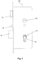
- Figure 2 shows an example of a side view of a known anti-panic mortise lock 10 with a device according to the invention mounted therein.
- Figure 3 equals to Figure 2 , shows the anti-panic mortise lock in a perspective view.
- a door locked by means of latch 13 and bolt 14 can be opened from the inside via a push actuation (actuation of the door handle) without using a key.
- the door can be unlocked from the inside and then opened without successful authentication (in panic situations).
- the door is also automatically locked after each door closing by means of a spring preload on the locking bolt.
- an opening or receptacle 11 is shown in which a lock cylinder can be inserted.
- it is the shape for a profile cylinder (PZ; see also Fig. 6 ).
- the device according to the invention is not limited to such locks or lock cases with profile cylinders and can also be used for Swiss round cylinders or other known cylinder shapes.
- the device for detecting the locking position is inserted into the corresponding opening 11 instead of a locking cylinder.
- the device covers the upper round section (see also "A" in Fig. 6 ) the opening 11 over an angular range of approximately 300 °.
- the device according to the invention preferably extends at least partially over the round (upper) section of the opening 11, so that in the section below (see "B” in FIG Fig. 6 ) a bracing element 203 or a wedge element 9 can be located.
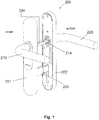
- FIG. 1 shows, for example, a fitting solution in which both the electronics and the mechanics for access control are arranged in the outer or inner fitting.
- the fitting 201 on the inside of the door comprises a handle 210 (inside door handle) which is fixedly coupled to the handle pin 204, which can be inserted into the nut 12 of the mortise lock.
- the fitting 200 also shows a corresponding outer fitting 202 with an outside lever 220.
- the outside lever 220 is coupled to the lever 204 of the inside fitting 201 via the modified lever pin 214.
- the inside handle pin 204 is always coupled to the nut 12 of the mortise lock, so that the anti-panic lock can always be opened when the inside handle is actuated.
- the outer handle pin 214 rotates without the inner handle 204 rotating, ie the outer door handle cannot actuate the mortise of the mortise lock, and the door is not opened from the outside. Only when authentication is successful are the two handles 204 and 214 coupled in such a way that a rotation of the outer handle 220 is transmitted to the inner handle pin 204, so that the door lock, ie the bolt and the latch, are opened.
- the fitting solution 220 shown is a special form of the fitting solution which is preferably attached to the door leaf without direct screwing.
- the outer and inner fittings are fastened here by means of a clamping element 203, which pulls or braces the outer and inner fittings against one another, this clamping element 203 preferably lying in the opening 11 of the mortise lock, which is provided for the locking cylinder.
- this clamping element 203 preferably lying in the opening 11 of the mortise lock, which is provided for the locking cylinder.
- the chipping element 203 of the embodiment in FIG Figure 1 has essentially a rectangular cross section, whereas the opening 11 in the mortise lock shown is a PZ opening, ie when a rectangular cross section is inserted, at least part of the upper cylindrical round part of the opening 11 remains free, even if the clamping element is arranged in the opening 11 ,
- the device according to the invention advantageously uses this space. In particular, it is precisely at this location of the mortise lock that contact or engagement with the bolt and / or the mechanism for actuating the bolt is possible, since a correspondingly arranged locking cylinder would actuate the bolt at this location with the help of the locking bar of the locking cylinder.
- the device according to the invention uses this special location to detect the locking position. In other words, the position of the bolt is determined from the inside within the mortise lock and not from the outside, as a result of which the device according to the invention is simple, safe and space-saving to assemble, ie the existing infrastructure can be used particularly advantageously.
- bracing element 203 it is preferred instead of the bracing element 203, insert a wedge 9 into the opening 11 of the mortise lock in order to ensure a secure fit of the device according to the invention in the opening 11 and preferably to prevent the device from rotating within the opening 11.
- a major preferred advantage of the present invention is that the device is roughly modeled on the outside of the conventional middle part of a lock cylinder with a lock bit and therefore, like this, can be inserted into a profile cylinder opening provided for this purpose, without modifications to a lock (ie the existing " Infrastructure ”) are required.
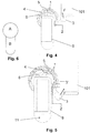
- the Figures 4 and 5 show the functioning of the device according to the invention on the basis of two different positions of the bolt or the locking mechanism 101.
- the device according to the invention comprises at least two parts 1 and 2 which can be rotated relative to one another.
- the first part is the inner part 1 and the second part is the outer part 2.
- the device can be described as a ring segment. Due to the expansion along the width of the lock case, the device could also be described as a cylinder segment, with a section that corresponds to a (round) cylinder wall over an angular range of approximately 200-300 °.
- the cross section of the device could also be referred to as "U-shaped" with a recess into which the bracing element 203 or the wedge 9 can be inserted in order to prevent the device from rotating within the opening 11.
- the inner part 2 and the outer part 1 are movable relative to one another, the inner part 2 preferably being mounted in the lock such that it cannot twist by means of the wedge 9 or the bracing element 203, so that in the mounted position only the outer part 1 remains relative to the lock case can move.
- the dimensions of this pushbutton element are modeled on a locking bit, so that the pushbutton element 3 according to the invention makes it possible to contact or engage in the locking mechanism as if a locking cylinder had been inserted into the opening 11.
- the feeler element 3 can be formed in one piece with the outer part 1 or fixedly attached to the outer part 1.
- the outer part 1 can have a fastening structure which is complementary to a fastening structure 3 ′ in the pushbutton element 3.
- that outer part 1 have a type of dovetail or backdrop structure into which corresponding "negative" shapes 3 ', which are formed in the probe element 3, can be inserted.
- the touch element 3 is preferably attached to the outer part 1 via a positive connection.
- This embodiment has the additional advantage that the sensing element 3 can be attached to the outer part 1 at different positions. The angular position of the feeler element 3 in the rest position can thus be set within certain limits.
- Fig. 4 shows a basic position. This basic position is detected by a sensor 6 present in the device.
- a rotation of two parts that can be rotated relative to one another can be detected by means of a large number of different sensors. Detection using a Hall sensor is particularly preferred.
- the Hall sensor 6 is preferably attached to the inner part 2 of the device.
- a Hall sensor can be present on a thin circuit board (for example a film circuit board), electronics for operating or evaluating the Hall sensor 6 already being present on the circuit board. Because of the electronics, it is preferred to attach the Hall sensor to the stationary part of the device, ie to the inner part 2. Because of the small size of the sensor, it is also possible to attach the sensor to the movable outer part 1.
- a small magnet is then attached to the other movable part and can be detected in a certain position with the Hall sensor 6.
- the small magnet 4 is attached to the outer part 1.
- the Hall sensor 6 is in the illustrated embodiment in Fig. 4 just below the magnet 4.
- the Hall sensor 6 detects the magnet 4 in this position; the latch position can accordingly be detected in accordance with the position of the component 101 which is part of the latch or part of the latch mechanism.
- the invention also includes the exact or exact terms, features, numerical values or ranges, etc., if above or below these terms, features, numerical values or ranges in connection with terms such as e.g. “approximately, approximately, um, essentially, generally, at least, at least” etc. (ie “approximately 3” should also include “3” or “substantially radial” should also include “radial”).
- the expression “or” also means “and / or”.
Landscapes
- Engineering & Computer Science (AREA)
- Structural Engineering (AREA)
- Business, Economics & Management (AREA)
- Emergency Management (AREA)
- Lock And Its Accessories (AREA)
Claims (16)
- Dispositif de détection d'une position de verrou d'une serrure à encastrer (10), qui est configuré pour être installé en lieu et place d'un cylindre de fermeture dans une ouverture (11), prévue pour un cylindre de fermeture, de la serrure à encastrer (10), avec :un élément palpeur (3), qui vient en contact avec le mécanisme d'actionnement du verrou ou le verrou (14) de la serrure à encastrer (10), dans lequel l'élément palpeur (3) est monté de manière à pouvoir tourner,et dans lequel une rotation de l'élément palpeur (3) est détectée avec un capteur (2).
- Dispositif selon la revendication 1, dans lequel l'élément palpeur (3) est poussé par une force contre le mécanisme d'actionnement du verrou ou le verrou (14), dans lequel ladite force est toutefois de préférence moins importante que la force avec laquelle le verrou de la serrure à encastrer (10) est poussé vers l'extérieur lors d'un verrouillage.
- Dispositif selon la revendication 1 ou 2, dans lequel l'élément palpeur (3) imite sensiblement un panneton de fermeture d'un cylindre de fermeture.
- Dispositif selon l'une quelconque des revendications précédentes, dans lequel la serrure à encastrer (10) est une serrure à encastrer anti-panique (10) à verrouillage automatique.
- Dispositif selon l'une quelconque des revendications précédentes, dans lequel le dispositif présente deux parties (1, 2) mobiles l'une par rapport à l'autre, qui sont fabriquées de préférence à partir de matière plastique.
- Dispositif selon la revendication 5, dans lequel les deux parties (1, 2) mobiles l'une par rapport à l'autre sont repoussées par un ressort (5) intercalé dans une position de départ, qui correspond de préférence à la position de verrou déverrouillée.
- Dispositif selon la revendication 6, dans lequel le ressort est un ressort de magasin (5), qui a de préférence une surface de base rectangulaire.
- Dispositif selon l'une quelconque des revendications précédentes, dans lequel le dispositif est adapté pour être installé, en plus d'un élément d'assemblage par serrage (203), qui assemble par serrage deux moitiés de ferrure de porte (201, 202) contre un vantail de porte et se situe dans l'ouverture (11), prévue pour le cylindre de fermeture, de la serrure à encastrer (10), dans ladite ouverture (11).
- Dispositif selon l'une quelconque des revendications précédentes, dans lequel le dispositif remplit seulement en partie l'ouverture (11), de préférence moins de 50 %, et un élément de calage (9) supplémentaire peut être introduit en plus du dispositif dans l'ouverture (11) pour bloquer le dispositif lors de l'actionnement du verrou (12) de la serrure pour empêcher toute rotation par rapport à la serrure à encastrer.
- Dispositif selon l'une quelconque des revendications précédentes, dans lequel l'élément palpeur (3) est tourné en fonction d'un changement de la position de verrou de la serrure à encastrer.
- Dispositif selon l'une quelconque des revendications précédentes, dans la mesure où elle dépend de la revendication 5, dans lequel la première partie (1) des deux parties (1, 2) est un élément annulaire (1) extérieur et est reliée à l'élément palpeur (3), et l'élément annulaire (1) extérieur est monté de manière à pouvoir tourner à l'extérieur de la seconde partie (2), qui est un élément central (2).
- Dispositif selon les revendications 6 et 11, dans lequel le ressort (5) se situe entre l'élément annulaire (1) extérieur et l'élément central (2) et génère une force de rotation relative par rapport auxdits deux éléments.
- Dispositif selon l'une quelconque des revendications 11 ou 12,
dans lequeli) l'élément palpeur (3) est réalisé d'un seul tenant avec l'élément annulaire (1) extérieur, ouii) l'élément palpeur (3) peut être fixé de manière amovible au niveau de l'élément annulaire (1) extérieur, de préférence au moyen d'éléments profilés s'imbriquant les uns dans les autres au niveau de l'élément annulaire (1) et de l'élément palpeur (3), ce qui permet de positionner l'élément palpeur (3) dans des positions angulaires différentes sur l'élément annulaire (1) pour permettre une adaptation à différents types de serrure, qui requièrent différentes positions angulaires. - Dispositif selon l'une quelconque des revendications précédentes, dans la mesure où elles dépendent de la revendication 5, dans lequel le capteur (2) est un capteur à effet Hall, qui est fixé dans la première ou la seconde partie, et l'autre de la première et de la seconde partie présente un aimant (4), qui peut être détecté avec le capteur à effet Hall.
- Procédé de détection d'une position de verrou d'une serrure à encastrer (10), avec les étapes :- de fourniture d'un dispositif selon l'une quelconque des revendications précédentes,- d'insertion du dispositif dans l'ouverture (11) de la serrure à encastrer (10), qui est prévue pour recevoir un cylindre de fermeture, en lieu et place d'un cylindre de fermeture.
- Procédé selon la revendication 15, avec l'étape supplémentaire de l'insertion d'un élément de calage (9) pour empêcher toute rotation du dispositif à l'intérieur de l'ouverture (11).
Applications Claiming Priority (1)
| Application Number | Priority Date | Filing Date | Title |
|---|---|---|---|
| DE102015006422 | 2015-05-19 |
Publications (2)
| Publication Number | Publication Date |
|---|---|
| EP3095934A1 EP3095934A1 (fr) | 2016-11-23 |
| EP3095934B1 true EP3095934B1 (fr) | 2019-12-18 |
Family
ID=56014921
Family Applications (1)
| Application Number | Title | Priority Date | Filing Date |
|---|---|---|---|
| EP16170178.4A Active EP3095934B1 (fr) | 2015-05-19 | 2016-05-18 | Dispositif de detection d'une position de verrou |
Country Status (1)
| Country | Link |
|---|---|
| EP (1) | EP3095934B1 (fr) |
Families Citing this family (3)
| Publication number | Priority date | Publication date | Assignee | Title |
|---|---|---|---|---|
| SE544588C2 (en) * | 2019-02-20 | 2022-09-13 | Bring Alot Konsult Ab | Switch arrangement with a triggering element and a sensor for being arranged in a locking mechanism and related system |
| CN111739187A (zh) * | 2020-07-17 | 2020-10-02 | 广东樱花智能科技有限公司 | 一种智能锁自动测试设备及测试方法 |
| WO2023114909A1 (fr) | 2021-12-17 | 2023-06-22 | Spectrum Brands, Inc. | Verrou électronique avec insert de mortaise |
Family Cites Families (5)
| Publication number | Priority date | Publication date | Assignee | Title |
|---|---|---|---|---|
| CH695160A5 (de) | 1999-01-20 | 2005-12-30 | Kaba Schliesssysteme Ag | Riegelüberwachung. |
| EP2391787B1 (fr) * | 2009-01-30 | 2015-06-03 | Corbin Russwin Architectural Hardware | Appareil de surveillance de cylindre de serrure |
| CN102597393B (zh) * | 2009-08-28 | 2016-06-08 | 福士西蒙科技有限责任公司 | 门装置 |
| DE102012025474B4 (de) * | 2012-12-29 | 2015-01-15 | Klaus Meister | Tür- und Riegelzustandsdetektionsvorrichtung |
| DE102013103515A1 (de) * | 2013-04-09 | 2014-10-09 | Keba Ag | Ladeanschlussvorrichtung für Elektrofahrzeuge |
-
2016
- 2016-05-18 EP EP16170178.4A patent/EP3095934B1/fr active Active
Non-Patent Citations (1)
| Title |
|---|
| None * |
Also Published As
| Publication number | Publication date |
|---|---|
| EP3095934A1 (fr) | 2016-11-23 |
Similar Documents
| Publication | Publication Date | Title |
|---|---|---|
| EP2703585B2 (fr) | Dispositif de serrure pour vantail passif doté d'un dispositif de tringlerie avec dispositif de protection contre la manipulation | |
| EP2525025B1 (fr) | Unité électronique pour un dispositif de verrouillage et système de fermeture | |
| EP3309333B1 (fr) | Système comprenant un châssis dormant destiné à loger un cadre de vantail | |
| DE102008063061A1 (de) | Betätigungsvorrichtung für ein elektronisches Türschloß | |
| EP3219886B1 (fr) | Barre de poussée comprenant un dispositif d'entraînement | |
| EP2391786B1 (fr) | Boîtier de sécurité | |
| DE102014112122B4 (de) | Verfahren zum Sperren und Freigeben eines Türblatts und Türanordnung | |
| EP2924202A1 (fr) | Serrure de porte ou de fenêtre | |
| DE202011103840U1 (de) | Schließanlage mit Mehrfachverriegelung für eine Tür | |
| EP3034719B1 (fr) | Dispositif d'actionnement d'un mecanisme de verrouillage d'une porte ou d'une fenetre | |
| EP3045623B1 (fr) | Dispositif de sécurisation de porte | |
| EP3095934A1 (fr) | Dispositif de détection d'une position de verrou | |
| EP2679751A2 (fr) | Dispositif de verrouillage et battant ou installation de battant équipé de celui-ci | |
| DE102010028647B3 (de) | Schloss | |
| EP1908899A2 (fr) | Système de verrouillage | |
| EP2862992B1 (fr) | Multi-serrure | |
| EP3219887A1 (fr) | Barre de poussée | |
| EP4372190B1 (fr) | Unité de fermeture électronique | |
| EP2060710B1 (fr) | Serrure | |
| DE102015119233B4 (de) | Sicherungsvorrichtung für eine Tür | |
| EP2924206B1 (fr) | Serrure de porte ou de fenêtre | |
| EP4524350B1 (fr) | Serrure | |
| EP2738324A2 (fr) | Serrure dotée d'une unité de rotation débloquable | |
| EP3892802B1 (fr) | Agencement de poignée de porte | |
| AT511829A4 (de) | Verriegelungseinrichtung sowie Rohrtresor mit einer Verriegelungseinrichtung |
Legal Events
| Date | Code | Title | Description |
|---|---|---|---|
| PUAI | Public reference made under article 153(3) epc to a published international application that has entered the european phase |
Free format text: ORIGINAL CODE: 0009012 |
|
| AK | Designated contracting states |
Kind code of ref document: A1 Designated state(s): AL AT BE BG CH CY CZ DE DK EE ES FI FR GB GR HR HU IE IS IT LI LT LU LV MC MK MT NL NO PL PT RO RS SE SI SK SM TR |
|
| AX | Request for extension of the european patent |
Extension state: BA ME |
|
| STAA | Information on the status of an ep patent application or granted ep patent |
Free format text: STATUS: REQUEST FOR EXAMINATION WAS MADE |
|
| 17P | Request for examination filed |
Effective date: 20170523 |
|
| RBV | Designated contracting states (corrected) |
Designated state(s): AL AT BE BG CH CY CZ DE DK EE ES FI FR GB GR HR HU IE IS IT LI LT LU LV MC MK MT NL NO PL PT RO RS SE SI SK SM TR |
|
| RIC1 | Information provided on ipc code assigned before grant |
Ipc: E05B 17/22 20060101AFI20190514BHEP Ipc: E05B 65/10 20060101ALI20190514BHEP Ipc: E05B 47/00 20060101ALN20190514BHEP Ipc: E05B 63/08 20060101ALI20190514BHEP Ipc: E05B 63/20 20060101ALI20190514BHEP |
|
| GRAP | Despatch of communication of intention to grant a patent |
Free format text: ORIGINAL CODE: EPIDOSNIGR1 |
|
| STAA | Information on the status of an ep patent application or granted ep patent |
Free format text: STATUS: GRANT OF PATENT IS INTENDED |
|
| INTG | Intention to grant announced |
Effective date: 20190621 |
|
| GRAS | Grant fee paid |
Free format text: ORIGINAL CODE: EPIDOSNIGR3 |
|
| GRAJ | Information related to disapproval of communication of intention to grant by the applicant or resumption of examination proceedings by the epo deleted |
Free format text: ORIGINAL CODE: EPIDOSDIGR1 |
|
| GRAL | Information related to payment of fee for publishing/printing deleted |
Free format text: ORIGINAL CODE: EPIDOSDIGR3 |
|
| STAA | Information on the status of an ep patent application or granted ep patent |
Free format text: STATUS: REQUEST FOR EXAMINATION WAS MADE |
|
| GRAR | Information related to intention to grant a patent recorded |
Free format text: ORIGINAL CODE: EPIDOSNIGR71 |
|
| STAA | Information on the status of an ep patent application or granted ep patent |
Free format text: STATUS: GRANT OF PATENT IS INTENDED |
|
| GRAA | (expected) grant |
Free format text: ORIGINAL CODE: 0009210 |
|
| STAA | Information on the status of an ep patent application or granted ep patent |
Free format text: STATUS: THE PATENT HAS BEEN GRANTED |
|
| INTG | Intention to grant announced |
Effective date: 20191107 |
|
| RIC1 | Information provided on ipc code assigned before grant |
Ipc: E05B 17/22 20060101AFI20191107BHEP Ipc: E05B 65/10 20060101ALI20191107BHEP Ipc: E05B 63/20 20060101ALI20191107BHEP Ipc: E05B 47/00 20060101ALN20191107BHEP Ipc: E05B 63/08 20060101ALI20191107BHEP |
|
| AK | Designated contracting states |
Kind code of ref document: B1 Designated state(s): AL AT BE BG CH CY CZ DE DK EE ES FI FR GB GR HR HU IE IS IT LI LT LU LV MC MK MT NL NO PL PT RO RS SE SI SK SM TR |
|
| REG | Reference to a national code |
Ref country code: CH Ref legal event code: EP |
|
| REG | Reference to a national code |
Ref country code: IE Ref legal event code: FG4D Free format text: LANGUAGE OF EP DOCUMENT: GERMAN |
|
| REG | Reference to a national code |
Ref country code: DE Ref legal event code: R096 Ref document number: 502016008035 Country of ref document: DE |
|
| REG | Reference to a national code |
Ref country code: AT Ref legal event code: REF Ref document number: 1214755 Country of ref document: AT Kind code of ref document: T Effective date: 20200115 |
|
| REG | Reference to a national code |
Ref country code: NL Ref legal event code: MP Effective date: 20191218 |
|
| PG25 | Lapsed in a contracting state [announced via postgrant information from national office to epo] |
Ref country code: FI Free format text: LAPSE BECAUSE OF FAILURE TO SUBMIT A TRANSLATION OF THE DESCRIPTION OR TO PAY THE FEE WITHIN THE PRESCRIBED TIME-LIMIT Effective date: 20191218 Ref country code: BG Free format text: LAPSE BECAUSE OF FAILURE TO SUBMIT A TRANSLATION OF THE DESCRIPTION OR TO PAY THE FEE WITHIN THE PRESCRIBED TIME-LIMIT Effective date: 20200318 Ref country code: NO Free format text: LAPSE BECAUSE OF FAILURE TO SUBMIT A TRANSLATION OF THE DESCRIPTION OR TO PAY THE FEE WITHIN THE PRESCRIBED TIME-LIMIT Effective date: 20200318 Ref country code: SE Free format text: LAPSE BECAUSE OF FAILURE TO SUBMIT A TRANSLATION OF THE DESCRIPTION OR TO PAY THE FEE WITHIN THE PRESCRIBED TIME-LIMIT Effective date: 20191218 Ref country code: LV Free format text: LAPSE BECAUSE OF FAILURE TO SUBMIT A TRANSLATION OF THE DESCRIPTION OR TO PAY THE FEE WITHIN THE PRESCRIBED TIME-LIMIT Effective date: 20191218 Ref country code: LT Free format text: LAPSE BECAUSE OF FAILURE TO SUBMIT A TRANSLATION OF THE DESCRIPTION OR TO PAY THE FEE WITHIN THE PRESCRIBED TIME-LIMIT Effective date: 20191218 Ref country code: GR Free format text: LAPSE BECAUSE OF FAILURE TO SUBMIT A TRANSLATION OF THE DESCRIPTION OR TO PAY THE FEE WITHIN THE PRESCRIBED TIME-LIMIT Effective date: 20200319 |
|
| REG | Reference to a national code |
Ref country code: LT Ref legal event code: MG4D |
|
| PG25 | Lapsed in a contracting state [announced via postgrant information from national office to epo] |
Ref country code: HR Free format text: LAPSE BECAUSE OF FAILURE TO SUBMIT A TRANSLATION OF THE DESCRIPTION OR TO PAY THE FEE WITHIN THE PRESCRIBED TIME-LIMIT Effective date: 20191218 Ref country code: RS Free format text: LAPSE BECAUSE OF FAILURE TO SUBMIT A TRANSLATION OF THE DESCRIPTION OR TO PAY THE FEE WITHIN THE PRESCRIBED TIME-LIMIT Effective date: 20191218 |
|
| PG25 | Lapsed in a contracting state [announced via postgrant information from national office to epo] |
Ref country code: AL Free format text: LAPSE BECAUSE OF FAILURE TO SUBMIT A TRANSLATION OF THE DESCRIPTION OR TO PAY THE FEE WITHIN THE PRESCRIBED TIME-LIMIT Effective date: 20191218 |
|
| PG25 | Lapsed in a contracting state [announced via postgrant information from national office to epo] |
Ref country code: NL Free format text: LAPSE BECAUSE OF FAILURE TO SUBMIT A TRANSLATION OF THE DESCRIPTION OR TO PAY THE FEE WITHIN THE PRESCRIBED TIME-LIMIT Effective date: 20191218 Ref country code: RO Free format text: LAPSE BECAUSE OF FAILURE TO SUBMIT A TRANSLATION OF THE DESCRIPTION OR TO PAY THE FEE WITHIN THE PRESCRIBED TIME-LIMIT Effective date: 20191218 Ref country code: EE Free format text: LAPSE BECAUSE OF FAILURE TO SUBMIT A TRANSLATION OF THE DESCRIPTION OR TO PAY THE FEE WITHIN THE PRESCRIBED TIME-LIMIT Effective date: 20191218 Ref country code: PT Free format text: LAPSE BECAUSE OF FAILURE TO SUBMIT A TRANSLATION OF THE DESCRIPTION OR TO PAY THE FEE WITHIN THE PRESCRIBED TIME-LIMIT Effective date: 20200513 Ref country code: CZ Free format text: LAPSE BECAUSE OF FAILURE TO SUBMIT A TRANSLATION OF THE DESCRIPTION OR TO PAY THE FEE WITHIN THE PRESCRIBED TIME-LIMIT Effective date: 20191218 |
|
| PG25 | Lapsed in a contracting state [announced via postgrant information from national office to epo] |
Ref country code: SM Free format text: LAPSE BECAUSE OF FAILURE TO SUBMIT A TRANSLATION OF THE DESCRIPTION OR TO PAY THE FEE WITHIN THE PRESCRIBED TIME-LIMIT Effective date: 20191218 Ref country code: SK Free format text: LAPSE BECAUSE OF FAILURE TO SUBMIT A TRANSLATION OF THE DESCRIPTION OR TO PAY THE FEE WITHIN THE PRESCRIBED TIME-LIMIT Effective date: 20191218 Ref country code: IS Free format text: LAPSE BECAUSE OF FAILURE TO SUBMIT A TRANSLATION OF THE DESCRIPTION OR TO PAY THE FEE WITHIN THE PRESCRIBED TIME-LIMIT Effective date: 20200418 |
|
| REG | Reference to a national code |
Ref country code: DE Ref legal event code: R097 Ref document number: 502016008035 Country of ref document: DE |
|
| PLBE | No opposition filed within time limit |
Free format text: ORIGINAL CODE: 0009261 |
|
| STAA | Information on the status of an ep patent application or granted ep patent |
Free format text: STATUS: NO OPPOSITION FILED WITHIN TIME LIMIT |
|
| PG25 | Lapsed in a contracting state [announced via postgrant information from national office to epo] |
Ref country code: DK Free format text: LAPSE BECAUSE OF FAILURE TO SUBMIT A TRANSLATION OF THE DESCRIPTION OR TO PAY THE FEE WITHIN THE PRESCRIBED TIME-LIMIT Effective date: 20191218 Ref country code: ES Free format text: LAPSE BECAUSE OF FAILURE TO SUBMIT A TRANSLATION OF THE DESCRIPTION OR TO PAY THE FEE WITHIN THE PRESCRIBED TIME-LIMIT Effective date: 20191218 |
|
| 26N | No opposition filed |
Effective date: 20200921 |
|
| PG25 | Lapsed in a contracting state [announced via postgrant information from national office to epo] |
Ref country code: SI Free format text: LAPSE BECAUSE OF FAILURE TO SUBMIT A TRANSLATION OF THE DESCRIPTION OR TO PAY THE FEE WITHIN THE PRESCRIBED TIME-LIMIT Effective date: 20191218 |
|
| PG25 | Lapsed in a contracting state [announced via postgrant information from national office to epo] |
Ref country code: LI Free format text: LAPSE BECAUSE OF NON-PAYMENT OF DUE FEES Effective date: 20200531 Ref country code: CH Free format text: LAPSE BECAUSE OF NON-PAYMENT OF DUE FEES Effective date: 20200531 Ref country code: MC Free format text: LAPSE BECAUSE OF FAILURE TO SUBMIT A TRANSLATION OF THE DESCRIPTION OR TO PAY THE FEE WITHIN THE PRESCRIBED TIME-LIMIT Effective date: 20191218 Ref country code: IT Free format text: LAPSE BECAUSE OF FAILURE TO SUBMIT A TRANSLATION OF THE DESCRIPTION OR TO PAY THE FEE WITHIN THE PRESCRIBED TIME-LIMIT Effective date: 20191218 |
|
| PG25 | Lapsed in a contracting state [announced via postgrant information from national office to epo] |
Ref country code: PL Free format text: LAPSE BECAUSE OF FAILURE TO SUBMIT A TRANSLATION OF THE DESCRIPTION OR TO PAY THE FEE WITHIN THE PRESCRIBED TIME-LIMIT Effective date: 20191218 |
|
| REG | Reference to a national code |
Ref country code: BE Ref legal event code: MM Effective date: 20200531 |
|
| GBPC | Gb: european patent ceased through non-payment of renewal fee |
Effective date: 20200518 |
|
| PG25 | Lapsed in a contracting state [announced via postgrant information from national office to epo] |
Ref country code: LU Free format text: LAPSE BECAUSE OF NON-PAYMENT OF DUE FEES Effective date: 20200518 |
|
| PG25 | Lapsed in a contracting state [announced via postgrant information from national office to epo] |
Ref country code: IE Free format text: LAPSE BECAUSE OF NON-PAYMENT OF DUE FEES Effective date: 20200518 Ref country code: GB Free format text: LAPSE BECAUSE OF NON-PAYMENT OF DUE FEES Effective date: 20200518 |
|
| PG25 | Lapsed in a contracting state [announced via postgrant information from national office to epo] |
Ref country code: BE Free format text: LAPSE BECAUSE OF NON-PAYMENT OF DUE FEES Effective date: 20200531 |
|
| PG25 | Lapsed in a contracting state [announced via postgrant information from national office to epo] |
Ref country code: TR Free format text: LAPSE BECAUSE OF FAILURE TO SUBMIT A TRANSLATION OF THE DESCRIPTION OR TO PAY THE FEE WITHIN THE PRESCRIBED TIME-LIMIT Effective date: 20191218 Ref country code: MT Free format text: LAPSE BECAUSE OF FAILURE TO SUBMIT A TRANSLATION OF THE DESCRIPTION OR TO PAY THE FEE WITHIN THE PRESCRIBED TIME-LIMIT Effective date: 20191218 Ref country code: CY Free format text: LAPSE BECAUSE OF FAILURE TO SUBMIT A TRANSLATION OF THE DESCRIPTION OR TO PAY THE FEE WITHIN THE PRESCRIBED TIME-LIMIT Effective date: 20191218 |
|
| PG25 | Lapsed in a contracting state [announced via postgrant information from national office to epo] |
Ref country code: MK Free format text: LAPSE BECAUSE OF FAILURE TO SUBMIT A TRANSLATION OF THE DESCRIPTION OR TO PAY THE FEE WITHIN THE PRESCRIBED TIME-LIMIT Effective date: 20191218 |
|
| REG | Reference to a national code |
Ref country code: AT Ref legal event code: MM01 Ref document number: 1214755 Country of ref document: AT Kind code of ref document: T Effective date: 20210518 |
|
| PG25 | Lapsed in a contracting state [announced via postgrant information from national office to epo] |
Ref country code: AT Free format text: LAPSE BECAUSE OF NON-PAYMENT OF DUE FEES Effective date: 20210518 |
|
| PGFP | Annual fee paid to national office [announced via postgrant information from national office to epo] |
Ref country code: DE Payment date: 20250530 Year of fee payment: 10 |
|
| PGFP | Annual fee paid to national office [announced via postgrant information from national office to epo] |
Ref country code: FR Payment date: 20250527 Year of fee payment: 10 |