EP2679940A2 - Passiver Verteiler von Kälteakkumulatoren, und entsprechender Kälteakkumulator - Google Patents
Passiver Verteiler von Kälteakkumulatoren, und entsprechender Kälteakkumulator Download PDFInfo
- Publication number
- EP2679940A2 EP2679940A2 EP13305885.9A EP13305885A EP2679940A2 EP 2679940 A2 EP2679940 A2 EP 2679940A2 EP 13305885 A EP13305885 A EP 13305885A EP 2679940 A2 EP2679940 A2 EP 2679940A2
- Authority
- EP
- European Patent Office
- Prior art keywords
- distributor
- enclosure
- accumulators
- double guide
- passive
- Prior art date
- Legal status (The legal status is an assumption and is not a legal conclusion. Google has not performed a legal analysis and makes no representation as to the accuracy of the status listed.)
- Granted
Links
Images



Classifications
-
- F—MECHANICAL ENGINEERING; LIGHTING; HEATING; WEAPONS; BLASTING
- F25—REFRIGERATION OR COOLING; COMBINED HEATING AND REFRIGERATION SYSTEMS; HEAT PUMP SYSTEMS; MANUFACTURE OR STORAGE OF ICE; LIQUEFACTION SOLIDIFICATION OF GASES
- F25D—REFRIGERATORS; COLD ROOMS; ICE-BOXES; COOLING OR FREEZING APPARATUS NOT OTHERWISE PROVIDED FOR
- F25D17/00—Arrangements for circulating cooling fluids; Arrangements for circulating gas, e.g. air, within refrigerated spaces
- F25D17/04—Arrangements for circulating cooling fluids; Arrangements for circulating gas, e.g. air, within refrigerated spaces for circulating air, e.g. by convection
- F25D17/06—Arrangements for circulating cooling fluids; Arrangements for circulating gas, e.g. air, within refrigerated spaces for circulating air, e.g. by convection by forced circulation
-
- F—MECHANICAL ENGINEERING; LIGHTING; HEATING; WEAPONS; BLASTING
- F25—REFRIGERATION OR COOLING; COMBINED HEATING AND REFRIGERATION SYSTEMS; HEAT PUMP SYSTEMS; MANUFACTURE OR STORAGE OF ICE; LIQUEFACTION SOLIDIFICATION OF GASES
- F25D—REFRIGERATORS; COLD ROOMS; ICE-BOXES; COOLING OR FREEZING APPARATUS NOT OTHERWISE PROVIDED FOR
- F25D25/00—Charging, supporting, and discharging the articles to be cooled
- F25D25/04—Charging, supporting, and discharging the articles to be cooled by conveyors
-
- F—MECHANICAL ENGINEERING; LIGHTING; HEATING; WEAPONS; BLASTING
- F25—REFRIGERATION OR COOLING; COMBINED HEATING AND REFRIGERATION SYSTEMS; HEAT PUMP SYSTEMS; MANUFACTURE OR STORAGE OF ICE; LIQUEFACTION SOLIDIFICATION OF GASES
- F25D—REFRIGERATORS; COLD ROOMS; ICE-BOXES; COOLING OR FREEZING APPARATUS NOT OTHERWISE PROVIDED FOR
- F25D31/00—Other cooling or freezing apparatus
- F25D31/006—Other cooling or freezing apparatus specially adapted for cooling receptacles, e.g. tanks
-
- G—PHYSICS
- G07—CHECKING-DEVICES
- G07F—COIN-FREED OR LIKE APPARATUS
- G07F11/00—Coin-freed apparatus for dispensing, or the like, discrete articles
- G07F11/02—Coin-freed apparatus for dispensing, or the like, discrete articles from non-movable magazines
- G07F11/34—Coin-freed apparatus for dispensing, or the like, discrete articles from non-movable magazines in which the magazines are of zig-zag form
-
- G—PHYSICS
- G07—CHECKING-DEVICES
- G07F—COIN-FREED OR LIKE APPARATUS
- G07F17/00—Coin-freed apparatus for hiring articles; Coin-freed facilities or services
- G07F17/0064—Coin-freed apparatus for hiring articles; Coin-freed facilities or services for processing of food articles
- G07F17/0071—Food articles which need to be processed for dispensing in a cold condition, e.g. ice and ice cream
-
- G—PHYSICS
- G07—CHECKING-DEVICES
- G07F—COIN-FREED OR LIKE APPARATUS
- G07F9/00—Details other than those peculiar to special kinds or types of apparatus
- G07F9/10—Casings or parts thereof, e.g. with means for heating or cooling
- G07F9/105—Heating or cooling means, for temperature and humidity control, for the conditioning of articles and their storage
Definitions
- the present invention relates to the distribution of cold accumulators.
- the respect of the cold chain makes it possible to preserve the taste qualities and the behavior of certain fresh products sensitive to the heat.
- the cold helps maintain the safety of products by preventing them from thawing.
- a first category of active devices makes it possible to keep products cold during a transport.
- coolers comprise a transportable insulated enclosure and a set of electric refrigeration powered by the vehicle's electrical circuit, in particular via a cigarette lighter plug.
- passive devices comprise an insulated enclosure, flexible or rigid, in which the products are kept cold using one or more cold accumulators.
- accumulators of cold take the form of a container, flexible or rigid, and containing water or a solution comprising a salt or a eutectic agent.
- the cold accumulator must be cooled, and in particular frozen, well in advance.
- the cold accumulator is generally cooled.
- the cold accumulator is used and begins to absorb calories from the user's departure from home and well before the fresh or frozen products are placed with the latter in the isolated enclosure.
- These distributors comprise an enclosure, electrical means for refrigeration, and means for distributing cooled accumulators, with a payment in return. According to a first drawback, the refrigeration means of these active distributors require regular maintenance.
- the present invention aims to overcome these disadvantages of the prior art by proposing a passive distributor of cold accumulators.
- the subject of the invention is a passive distributor of cold accumulators, the dispenser comprising an enclosure intended to be placed in a refrigerated outer enclosure of greater volume, storage and distribution means for cold accumulators disposed inside this enclosure, an input for charging the storage means with accumulators to be cooled, and an output through which are distributed the accumulators cooled by the distribution means, the distributor chamber comprising a connected lower wall to an upper wall by side walls, as well as an anterior wall and a posterior wall.
- the passive distributor of cold accumulators is characterized in that it comprises at least one air inlet equipped with air suction means for capturing the frigories from outside the enclosure and circulate them inside the enclosure.
- the invention also proposes a cold accumulator intended to be used with the storage and dispensing means of this dispenser, the accumulator being characterized in that it takes the form of a cylindrical element of external diameter adapted to the means of storage and distribution of this dispenser, and in that it comprises a central cylindrical portion of reduced diameter relative to the outer diameter of the cylindrical member.
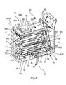
- the present invention relates to a passive distributor 10 of cold accumulators 12, as shown in FIG. figure 1 .
- the invention means a dispenser that does not include electric refrigerant means capable of producing cold, as can be active distributors of the prior art.
- the dispenser 10 comprises an enclosure 14 intended to be placed in a refrigerated outer enclosure of greater volume, such as for example a refrigerated container used as a gondola in a store and in which the products are left in position. self-service.
- the enclosure 14 of the distributor 10 comprises a bottom wall 16 connected to an upper wall 18 by side walls 20D, 20G, as well as by an anterior wall 22 and a rear wall 24.
- the various walls 16, 18, 20D, 20G, 22, 24 are rectangular and the enclosure 14 is parallelepipedal.
- the lower walls 16, upper 18, lateral 20D, 20G, anterior 22 and posterior 24 are made of a thermally conductive material, in particular metal.
- the dispenser 10 comprises storage means 26 and distribution 28 of accumulators 12 of cold disposed inside the enclosure 14, a input 30 for charging the storage means 26 with accumulators 12 to be cooled, and an outlet 32 through which are distributed the accumulators 12 cooled by the distribution means 28.
- the distributor 10 comprises an air inlet 34 equipped with air suction means 36, as shown in the bottom view in figure 3 .
- the air inlet 34 is an opening 38 made in the lower wall 16 and in which the suction means are installed. air 36.
- the distributor 10 may comprise several air inlets 34-1,34-2 equipped with their air suction means 36.
- each of these air inlets 34-1, 34-2 takes the form of an opening 38 made in the bottom wall 16 and in which the air suction means 36 are installed.
- the air suction means 36 take the form of a fan 40 disposed across the opening 38.
- the blades 42 of the fan 40 are oriented so as to suck the air from the outside E of the enclosure 14 to propel it inside I of the enclosure 14 .
- the distributor 10 comprises P feet for raising the lower wall 16 relative to the surface S on which is deposited the distributor 10.
- the dispenser 10 comprises four legs P at the four corners of the bottom wall 16.
- a side wall 20D, 20G comprises, at least in its upper part 44 , a perforated surface 46 composed of a plurality of openings 48.
- each side wall 20D, 20G comprises several perforated surfaces 46, superimposed in the height H10 of the distributor 10 or juxtaposed in the length L10 of the distributor 10.
- the perforated surfaces 46, superimposed or juxtaposed extend substantially throughout the height H10 of the distributor 10 and throughout the length L10 of the distributor 10.
- the loading inlet 30 of the storage means 26 and the outlet 32 of the distribution means 28 comprise separate openings 30 'and 32' and made in the upper wall 24 of the enclosure 14 of the dispenser.
- the storage means 26 of the accumulators 12 to be cooled take the form of two double guide rails 50D, 50G spaced in the width W10 of the distributor 10 and parallel, the double guide rails 50D, 50G forming a double guide path CG for accumulators 12.
- the double guiding path CG formed by the double guide rails 50D, 50G is continuously descending from the upper wall 18 to the lower wall 16 of the enclosure 14 of the dispenser.
- the double guide path CG formed by the double guide rails 50D, 50G zigzags downwardly between the anterior wall 22 and the posterior wall 24.
- Each double guide rail 50D, 50G is formed by two guides 52,52 'snaking in the same guide plane PG on either side, and equidistant from the double guide path CG.
- An accumulator 12 taking the form of a cylindrical element 54 of outside diameter D54 adapted to the storage 26 and dispensing means 28 of the distributor 10, the distance d between the two guides 52, 52 'of each double rail of 50D guide, 50G and the double guide path CG is at most equal, clearance, to half the outer diameter D54. Also, the spacing e1 between the two double guide rails 50D, 50G is smaller than the length L54 of the cylindrical element 54.
- each double guide rail 50D, 50G are rigid wires shaped and supported by means of an internal frame 56 comprising two lateral supports 58D, 58G parallel to the side walls 20D, 20G of the enclosure 14, and axes 60 connecting these two lateral supports 58D, 58G and now the guides 52,52 'in the sections 62,62' where they change direction, either in the turns of the double guide path CG.
- the guides 52, 52 ' are preferably solid, cylindrical, metallic wires, and shaped so as to have straight portions and alternately bent portions.
- each double guide rail 50D, 50G are constituted by the edges 110, 110' of cutouts 112D, 112G made in side plates 116D, 116G spaced apart from one another, parallel to the side walls 20D , 20G of the enclosure 14 and forming an inner frame 114, axes 61 connecting these two side plates 116D, 116G and now the guides 52,52 'in the sections 62,62' where they change direction, either in bends the double guide path CG.
- This second variant of the storage means 26 is more economical to manufacture because it is cheaper to cut metal plates than to bend wire.
- this second variant of the storage means 26 increases the operating reliability of the distributor 10.
- the input 66 of the distribution means 28 is located just above the rear portion 68 of the lower wall 16, the double CG guideway, and therefore the two guides 52,52 'of each double guide rail 50D, 50G, stop just above the rear portion 68 of the bottom wall 16.
- the distribution means 28 of the cooled accumulators 12 take the form of elevating means 70 associated with guide means 72 making it possible to stack the accumulators 12 from the inlet 66 of these distribution means 28 to the outlet 32 of the means distribution 28.
- the guide means 72 take the form of a double guide rail 84 and a guide plate 94 extending from the bottom wall 16 to the upper wall 24 of the enclosure 14.
- the lifting means 70 take the form of a wheel 74 with blades 76, each blade 76 for receiving an accumulator 12.
- the wheel 74 is rotatably mounted in the inlet 66 of the distribution means 28 around a fixed axis of rotation A74 and driven in rotation by a jack 80 whose body 82 is connected to the enclosure 14.
- the accumulators 12 being stored transversely bearing on the double guide rails 50D, 50G, the axis of rotation A74 of the wheel 74 is mounted perpendicularly to the guide plane PG of the guideways CG of the storage means 26.
- the accumulator 12 comprises a cylindrical central portion 55 of reduced diameter relative to the outer diameter D54 of the cylindrical element 54.
- the cylindrical central portion 55 has a width W55 corresponding, with the clearance, to the width W76 of a blade 76.
- the two cylindrical side portions 57D and 57G located on either side of the central portion 55 of reduced diameter can be used for guiding the accumulator 12 in the storage means 26 and in the distribution means 28.
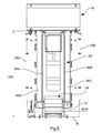
- the central portion 55 of reduced diameter is preferably used for guiding the accumulator 12 in the storage means 26 and in the distribution means 28, as illustrated by figure 6 .
- the cylindrical central portion 55 having a width W55 corresponding, with clearance, to the spacing e1 of the rails 50D, 50G forming the storage means 26 and at the spacing e2 of the double guide rail 84 forming the distribution means 28, the two cylindrical side portions 57D and 57G make it possible to stabilize the accumulator 12 during its guiding in the storage means 26 and in the distribution means 28.
- the central portion 55 of the accumulator 12 comprises lateral grooves 59D, 59G contiguous to the two cylindrical side portions 57D and 57G of diameter D54.
- the spacing e59 between the lateral grooves 59D, 59G corresponds to the spacing e1 of the rails 50D, 50G forming the storage means 26 and to the spacing e2 of the double guide rail 84 forming the distribution means 28.
- the lateral grooves 59D, 59G make it possible to better stabilize the accumulator 12 and to maintain it substantially perpendicular to the guide plane PG during its descent into the storage means 26 and its rise in the means of distribution 28.
- the double guide rail 84 is formed by two guides 86D, 86G spaced in the width W10 of the distributor 10 and parallel.
- the spacing e2 between the two guides 86D, 86G is less than the length L54 of the cylindrical element 54, and equal to the spacing e1 between the two double guide rails 50D, 50G.
- Each guide 86D, 86G comprises an input curve portion 88 for receiving the accumulators 12 arriving from the storage means 26, then a straight intermediate portion 90 in the height H10 of the distributor, and a curved output portion 92 bringing the accumulators 12 to exit 32
- the curvature of the inlet 88 and outlet 92 portions facilitates the transition of the accumulators 12 transported to or from the rectilinear intermediate portion 90.
- the two guides 86D, 86G of the double guide rail 84 are extensions of the rigid and shaped wires forming the guides 52, 52 'of each of the double guide rails 50D, 50G of the storage means 26, and more particularly of the 52.52 'which is below the other in front of the inlet 66 of the distribution means 28.
- the two guides 86D, 86G of the double guide rail 84 are extensions of the edge 110, 10 'of the cuts 112D, 112G which lies below the other in front of the inlet 66 of the distribution means 28, and the plateau guide 94 is formed by extensions of the edge 110, 110 'of the blanks 112D, 112G which is located above the other in front of the inlet 66 of the distribution means 28.
- the two guides 86D, 86G of the double guide rail 84 allow, through the guiding of the lateral portions 57D, 57G of the accumulators 12 transported, to control the trajectory of the accumulators 12 to the output 32 of the distribution means 28.
- the guide plate 94 is spaced from this double guide rail 84 so as to allow the passage, with the game, accumulators 12 which are stacked under the effect of the lifting means 70.
- FIG. 1 In one embodiment of the invention, FIG.
- the guide plate 94 comprises two guiding surfaces 98D, 98G distinct and parallel to the rectilinear intermediate portion 90 of the double guide rail 84, the accumulators 12, and in particular their lateral portions 57D, 57G, sliding between these guide surfaces 98D , 98G and the two guides 86D, 86G of the double guide rail 84 when they gradually stack up to the outlet 32 of the distribution means 28 under the effect of the rotation of the wheel 74.
- the wheel 74 is articulated in rotation at the end of the rod 78 of the jack 80 via an eccentric 100, and the wheel 74 is mounted around its fixed axis of rotation A74 via a rotating anti-return device, said to ratchet and known to those skilled in the art.
- the wheel 74 is driven in a loading rotation R1 about its fixed axis of rotation A74, which makes it possible to load a new accumulator 12 in the guide means 72 to using a blade 76 and push a notch accumulators 12 already stacked in the guide means 72.
- the jack 80 and the eccentric 100 can be offset to the outside E of the enclosure 14.
- the outlet 32 of the distribution means 28 takes the form of a hollow and inclined plate 102, the lower end 103 of this plate 102 being placed below the opening 32 'made in the upper wall 18.
- this plate 102 is disposed just at the end of the curved outlet portion 92 of the guides 86D, 86G.
- the loading inlet 30 of the storage means 26 takes the form of a cylindrical roller 104 rotatably mounted around its central axis A104, below the opening 30 'made in the upper wall 18, and comprising several , three for example, longitudinal clearances 106 each for receiving a battery 12.
- the accumulator 12 taking the form of a cylindrical element 54, the longitudinal recesses 106 are also cylindrical.
- this cylindrical roller 104 is mounted perpendicularly to the guide plane PG guideways CG storage means 26, this in order to deposit the accumulators 12 transversely bearing on the double guide rails 50D, 50G.
- the roller 104 completely closes the loading inlet 30 of the storage means 26 in order to prevent a person from recovering an accumulator 12 through this input.
- the openings 48 of the perforated surfaces 46 of the side walls 20D, 20G are more narrow than the outer diameter D54 of the cylindrical element 54 forming an accumulator 12.
- the user retrieves a cooled accumulator 12 in exchange for charging an accumulator 12 in the storage means 26.
- the operation of the distribution means 28 and the delivery of a cooled accumulator 12 are slaved to the arrival of a new accumulator 12 in the storage means 26.
- different detection means known from Those skilled in the art can equip the storage means 26 downstream of the loading inlet 30 to detect each new arrival of an accumulator 12.
- the cylindrical element 54 forming the accumulator 12 according to the invention, is hollow so as to provide a reservoir for containing water or a solution comprising a salt or a eutectic agent.
- the dispenser 10 makes it possible to store 80 to 90 accumulators 12.
- the dispenser 10 may be equipped with display means 108 for explaining to users the operation of the dispenser 10 and the principle of exchanging the accumulators.
- the dispenser 10 according to the invention offers a simple and reliable design, and does not require maintenance of electrical refrigerant means.
Landscapes
- Engineering & Computer Science (AREA)
- Physics & Mathematics (AREA)
- General Physics & Mathematics (AREA)
- Chemical & Material Sciences (AREA)
- Combustion & Propulsion (AREA)
- Mechanical Engineering (AREA)
- Thermal Sciences (AREA)
- General Engineering & Computer Science (AREA)
- Life Sciences & Earth Sciences (AREA)
- Food Science & Technology (AREA)
Applications Claiming Priority (1)
| Application Number | Priority Date | Filing Date | Title |
|---|---|---|---|
| FR1256043A FR2992406A1 (fr) | 2012-06-26 | 2012-06-26 | Distributeur passif d'accumulateurs de froid et accumulateur de froid associe |
Publications (3)
| Publication Number | Publication Date |
|---|---|
| EP2679940A2 true EP2679940A2 (de) | 2014-01-01 |
| EP2679940A3 EP2679940A3 (de) | 2014-01-15 |
| EP2679940B1 EP2679940B1 (de) | 2019-11-13 |
Family
ID=48741015
Family Applications (1)
| Application Number | Title | Priority Date | Filing Date |
|---|---|---|---|
| EP13305885.9A Active EP2679940B1 (de) | 2012-06-26 | 2013-06-26 | Passiver Spender von Kältespeichern und Verfahren zur Verwendung eines solchen Spenders |
Country Status (2)
| Country | Link |
|---|---|
| EP (1) | EP2679940B1 (de) |
| FR (1) | FR2992406A1 (de) |
Cited By (1)
| Publication number | Priority date | Publication date | Assignee | Title |
|---|---|---|---|---|
| WO2017192591A1 (en) * | 2016-05-02 | 2017-11-09 | The Coca-Cola Company | Vending mechanism |
Family Cites Families (6)
| Publication number | Priority date | Publication date | Assignee | Title |
|---|---|---|---|---|
| DE3215627A1 (de) * | 1982-04-27 | 1983-11-03 | Paul Hettler | Kuehlbomben-umlaufsystem mit verkaufs-automatisation |
| EP0140153A3 (en) * | 1983-10-27 | 1986-07-30 | Gyorgy Teglasy | Coin-operated apparatus for dispensing cooling elements |
| DE8520184U1 (de) * | 1985-07-12 | 1986-11-06 | Galambos, Ludwig, 2000 Hamburg | Münzenbetätigbarer Automat zum Austauschen von verbrauchten Kühlelementen gegen aktivierte Kühlelemente |
| FR2745933B1 (fr) * | 1996-03-11 | 1998-06-12 | Alvaro Gonzalez | Appareil distributeur d'elements refrigerants et lesdits elements refrigerants |
| FR2807190B1 (fr) * | 2000-03-29 | 2002-06-28 | Internova Int Innovation | Appareil distributeur d'elements refrigerants rechargeables |
| ATE519997T1 (de) * | 2003-05-08 | 2011-08-15 | Welita Gmbh | Verfahren zum abkühlen von plattenförmigen kühlelementen und/oder kühlgut und kühlgutvorrichtung dafür |
-
2012
- 2012-06-26 FR FR1256043A patent/FR2992406A1/fr active Pending
-
2013
- 2013-06-26 EP EP13305885.9A patent/EP2679940B1/de active Active
Cited By (2)
| Publication number | Priority date | Publication date | Assignee | Title |
|---|---|---|---|---|
| WO2017192591A1 (en) * | 2016-05-02 | 2017-11-09 | The Coca-Cola Company | Vending mechanism |
| US10930107B2 (en) | 2016-05-02 | 2021-02-23 | The Coca-Cola Company | Vending mechanism |
Also Published As
| Publication number | Publication date |
|---|---|
| EP2679940A3 (de) | 2014-01-15 |
| FR2992406A1 (fr) | 2013-12-27 |
| EP2679940B1 (de) | 2019-11-13 |
Similar Documents
| Publication | Publication Date | Title |
|---|---|---|
| EP0824739B1 (de) | Ausgabeautomat für kühlelemente und entsprechende kühlelemente | |
| WO2007054636A1 (fr) | Distributeur de produits alimentaires notamment de boissons | |
| US10388101B2 (en) | Merchandiser | |
| US8181821B2 (en) | Dispenser assembly | |
| US20090278009A1 (en) | Liquid storage and dispensing device and method thereof | |
| EP2724960B1 (de) | Anlage zur Lagerung und Ausgabe von Arzneimittelpackungen | |
| US20170076532A1 (en) | Merchandiser | |
| EP0905660A1 (de) | Vorrichtung zum Lösen und Spenden von Artikeln | |
| FR2998890A1 (fr) | Procede et appareil de conservation et distribution d'un produit alimentaire, en particulier d'un yoghourt | |
| FR2998889A1 (fr) | Appareil compact de conservation et distribution d'un produit alimentaire, en particulier d'un yoghourt | |
| EP2679940B1 (de) | Passiver Spender von Kältespeichern und Verfahren zur Verwendung eines solchen Spenders | |
| US10676008B2 (en) | Methods and systems for preparing, packaging, and distributing a frozen confection | |
| FR2749960A1 (fr) | Distributeur automatique de fleurs fraiches coupees confectionnant des bouquets a la demande | |
| EP0968395B1 (de) | Gekühlter servierwagen | |
| CA2404637C (fr) | Appareil distributeur d'elements refrigerants rechargeables | |
| WO1987000664A1 (fr) | Dispositif de distribution et de vente de supports souples | |
| FR2671950A1 (fr) | Container mobile destine au transport de denrees alimentaires a deux temperatures differentes muni d'un dispositif de presentation automatique des plateaux a hauteur d'operateur. | |
| FR2458851A1 (fr) | Distributeur cryogenique | |
| BE1031146B1 (fr) | Appareil pour conserver et distribuer un produit alimentaire et un réservoir de produit alimentaire | |
| FR2917719A1 (fr) | Dispositif pour ouvrir et distribuer des barquettes contenant des repas ou des boissons principalement destines a l'alimentation d'animaux tels que les chiens et les chats | |
| JPH08235431A (ja) | 自動販売機の商品搬出装置 | |
| BE519489A (de) | ||
| WO2016079434A1 (fr) | Installation pour rafraîchir des produits en présence d'une couche de glace | |
| FR3018598A1 (fr) | Dispositif de distribution de glace a des chariots de transports de produits a conserver par le froid | |
| WO2004051368A1 (fr) | Dispositif pour le stockage et la distribution d'objets |
Legal Events
| Date | Code | Title | Description |
|---|---|---|---|
| PUAL | Search report despatched |
Free format text: ORIGINAL CODE: 0009013 |
|
| PUAI | Public reference made under article 153(3) epc to a published international application that has entered the european phase |
Free format text: ORIGINAL CODE: 0009012 |
|
| AK | Designated contracting states |
Kind code of ref document: A2 Designated state(s): AL AT BE BG CH CY CZ DE DK EE ES FI FR GB GR HR HU IE IS IT LI LT LU LV MC MK MT NL NO PL PT RO RS SE SI SK SM TR |
|
| AX | Request for extension of the european patent |
Extension state: BA ME |
|
| AK | Designated contracting states |
Kind code of ref document: A3 Designated state(s): AL AT BE BG CH CY CZ DE DK EE ES FI FR GB GR HR HU IE IS IT LI LT LU LV MC MK MT NL NO PL PT RO RS SE SI SK SM TR |
|
| AX | Request for extension of the european patent |
Extension state: BA ME |
|
| RIC1 | Information provided on ipc code assigned before grant |
Ipc: F25D 13/06 20060101ALI20131212BHEP Ipc: F25D 25/04 20060101ALI20131212BHEP Ipc: F25D 3/00 20060101AFI20131212BHEP Ipc: F25D 31/00 20060101ALI20131212BHEP Ipc: F25D 17/06 20060101ALI20131212BHEP |
|
| 17P | Request for examination filed |
Effective date: 20140705 |
|
| RBV | Designated contracting states (corrected) |
Designated state(s): AL AT BE BG CH CY CZ DE DK EE ES FI FR GB GR HR HU IE IS IT LI LT LU LV MC MK MT NL NO PL PT RO RS SE SI SK SM TR |
|
| RAP1 | Party data changed (applicant data changed or rights of an application transferred) |
Owner name: FRIODIS |
|
| 111L | Licence recorded |
Designated state(s): AL AT BE BG CH CY CZ DE DK EE ES FI FR GB GR HR HU IE IS IT LT LU LV MC MK MT NL NO PL PT RO RS SE SI SK SM TR Free format text: EXCLUSIVE LICENSE Name of requester: FUTURINOV, FR Effective date: 20140917 |
|
| STAA | Information on the status of an ep patent application or granted ep patent |
Free format text: STATUS: EXAMINATION IS IN PROGRESS |
|
| 17Q | First examination report despatched |
Effective date: 20181128 |
|
| GRAP | Despatch of communication of intention to grant a patent |
Free format text: ORIGINAL CODE: EPIDOSNIGR1 |
|
| STAA | Information on the status of an ep patent application or granted ep patent |
Free format text: STATUS: GRANT OF PATENT IS INTENDED |
|
| INTG | Intention to grant announced |
Effective date: 20190403 |
|
| GRAJ | Information related to disapproval of communication of intention to grant by the applicant or resumption of examination proceedings by the epo deleted |
Free format text: ORIGINAL CODE: EPIDOSDIGR1 |
|
| STAA | Information on the status of an ep patent application or granted ep patent |
Free format text: STATUS: EXAMINATION IS IN PROGRESS |
|
| GRAS | Grant fee paid |
Free format text: ORIGINAL CODE: EPIDOSNIGR3 |
|
| STAA | Information on the status of an ep patent application or granted ep patent |
Free format text: STATUS: GRANT OF PATENT IS INTENDED |
|
| GRAP | Despatch of communication of intention to grant a patent |
Free format text: ORIGINAL CODE: EPIDOSNIGR1 |
|
| INTC | Intention to grant announced (deleted) | ||
| INTG | Intention to grant announced |
Effective date: 20190827 |
|
| GRAA | (expected) grant |
Free format text: ORIGINAL CODE: 0009210 |
|
| STAA | Information on the status of an ep patent application or granted ep patent |
Free format text: STATUS: THE PATENT HAS BEEN GRANTED |
|
| 111L | Licence recorded |
Designated state(s): AL AT BE BG CH CY CZ DE DK EE ES FI FR GB GR HR HU IE IS IT LT LU LV MC MK MT NL NO PL PT RO RS SE SI SK SM TR Free format text: EXCLUSIVE LICENSE Name of requester: FUTURINOV, FR Effective date: 20140917 |
|
| AK | Designated contracting states |
Kind code of ref document: B1 Designated state(s): AL AT BE BG CH CY CZ DE DK EE ES FI FR GB GR HR HU IE IS IT LI LT LU LV MC MK MT NL NO PL PT RO RS SE SI SK SM TR |
|
| REG | Reference to a national code |
Ref country code: CH Ref legal event code: EP Ref country code: AT Ref legal event code: REF Ref document number: 1202082 Country of ref document: AT Kind code of ref document: T Effective date: 20191115 |
|
| REG | Reference to a national code |
Ref country code: DE Ref legal event code: R096 Ref document number: 602013062818 Country of ref document: DE |
|
| REG | Reference to a national code |
Ref country code: IE Ref legal event code: FG4D Free format text: LANGUAGE OF EP DOCUMENT: FRENCH |
|
| REG | Reference to a national code |
Ref country code: NL Ref legal event code: MP Effective date: 20191113 |
|
| REG | Reference to a national code |
Ref country code: LT Ref legal event code: MG4D |
|
| PG25 | Lapsed in a contracting state [announced via postgrant information from national office to epo] |
Ref country code: PL Free format text: LAPSE BECAUSE OF FAILURE TO SUBMIT A TRANSLATION OF THE DESCRIPTION OR TO PAY THE FEE WITHIN THE PRESCRIBED TIME-LIMIT Effective date: 20191113 Ref country code: NL Free format text: LAPSE BECAUSE OF FAILURE TO SUBMIT A TRANSLATION OF THE DESCRIPTION OR TO PAY THE FEE WITHIN THE PRESCRIBED TIME-LIMIT Effective date: 20191113 Ref country code: SE Free format text: LAPSE BECAUSE OF FAILURE TO SUBMIT A TRANSLATION OF THE DESCRIPTION OR TO PAY THE FEE WITHIN THE PRESCRIBED TIME-LIMIT Effective date: 20191113 Ref country code: LV Free format text: LAPSE BECAUSE OF FAILURE TO SUBMIT A TRANSLATION OF THE DESCRIPTION OR TO PAY THE FEE WITHIN THE PRESCRIBED TIME-LIMIT Effective date: 20191113 Ref country code: BG Free format text: LAPSE BECAUSE OF FAILURE TO SUBMIT A TRANSLATION OF THE DESCRIPTION OR TO PAY THE FEE WITHIN THE PRESCRIBED TIME-LIMIT Effective date: 20200213 Ref country code: FI Free format text: LAPSE BECAUSE OF FAILURE TO SUBMIT A TRANSLATION OF THE DESCRIPTION OR TO PAY THE FEE WITHIN THE PRESCRIBED TIME-LIMIT Effective date: 20191113 Ref country code: PT Free format text: LAPSE BECAUSE OF FAILURE TO SUBMIT A TRANSLATION OF THE DESCRIPTION OR TO PAY THE FEE WITHIN THE PRESCRIBED TIME-LIMIT Effective date: 20200313 Ref country code: NO Free format text: LAPSE BECAUSE OF FAILURE TO SUBMIT A TRANSLATION OF THE DESCRIPTION OR TO PAY THE FEE WITHIN THE PRESCRIBED TIME-LIMIT Effective date: 20200213 Ref country code: GR Free format text: LAPSE BECAUSE OF FAILURE TO SUBMIT A TRANSLATION OF THE DESCRIPTION OR TO PAY THE FEE WITHIN THE PRESCRIBED TIME-LIMIT Effective date: 20200214 Ref country code: LT Free format text: LAPSE BECAUSE OF FAILURE TO SUBMIT A TRANSLATION OF THE DESCRIPTION OR TO PAY THE FEE WITHIN THE PRESCRIBED TIME-LIMIT Effective date: 20191113 Ref country code: ES Free format text: LAPSE BECAUSE OF FAILURE TO SUBMIT A TRANSLATION OF THE DESCRIPTION OR TO PAY THE FEE WITHIN THE PRESCRIBED TIME-LIMIT Effective date: 20191113 |
|
| PG25 | Lapsed in a contracting state [announced via postgrant information from national office to epo] |
Ref country code: RS Free format text: LAPSE BECAUSE OF FAILURE TO SUBMIT A TRANSLATION OF THE DESCRIPTION OR TO PAY THE FEE WITHIN THE PRESCRIBED TIME-LIMIT Effective date: 20191113 Ref country code: IS Free format text: LAPSE BECAUSE OF FAILURE TO SUBMIT A TRANSLATION OF THE DESCRIPTION OR TO PAY THE FEE WITHIN THE PRESCRIBED TIME-LIMIT Effective date: 20200313 Ref country code: HR Free format text: LAPSE BECAUSE OF FAILURE TO SUBMIT A TRANSLATION OF THE DESCRIPTION OR TO PAY THE FEE WITHIN THE PRESCRIBED TIME-LIMIT Effective date: 20191113 |
|
| PG25 | Lapsed in a contracting state [announced via postgrant information from national office to epo] |
Ref country code: AL Free format text: LAPSE BECAUSE OF FAILURE TO SUBMIT A TRANSLATION OF THE DESCRIPTION OR TO PAY THE FEE WITHIN THE PRESCRIBED TIME-LIMIT Effective date: 20191113 |
|
| PG25 | Lapsed in a contracting state [announced via postgrant information from national office to epo] |
Ref country code: RO Free format text: LAPSE BECAUSE OF FAILURE TO SUBMIT A TRANSLATION OF THE DESCRIPTION OR TO PAY THE FEE WITHIN THE PRESCRIBED TIME-LIMIT Effective date: 20191113 Ref country code: CZ Free format text: LAPSE BECAUSE OF FAILURE TO SUBMIT A TRANSLATION OF THE DESCRIPTION OR TO PAY THE FEE WITHIN THE PRESCRIBED TIME-LIMIT Effective date: 20191113 Ref country code: DK Free format text: LAPSE BECAUSE OF FAILURE TO SUBMIT A TRANSLATION OF THE DESCRIPTION OR TO PAY THE FEE WITHIN THE PRESCRIBED TIME-LIMIT Effective date: 20191113 Ref country code: EE Free format text: LAPSE BECAUSE OF FAILURE TO SUBMIT A TRANSLATION OF THE DESCRIPTION OR TO PAY THE FEE WITHIN THE PRESCRIBED TIME-LIMIT Effective date: 20191113 |
|
| REG | Reference to a national code |
Ref country code: DE Ref legal event code: R097 Ref document number: 602013062818 Country of ref document: DE |
|
| REG | Reference to a national code |
Ref country code: AT Ref legal event code: MK05 Ref document number: 1202082 Country of ref document: AT Kind code of ref document: T Effective date: 20191113 |
|
| PG25 | Lapsed in a contracting state [announced via postgrant information from national office to epo] |
Ref country code: SM Free format text: LAPSE BECAUSE OF FAILURE TO SUBMIT A TRANSLATION OF THE DESCRIPTION OR TO PAY THE FEE WITHIN THE PRESCRIBED TIME-LIMIT Effective date: 20191113 Ref country code: SK Free format text: LAPSE BECAUSE OF FAILURE TO SUBMIT A TRANSLATION OF THE DESCRIPTION OR TO PAY THE FEE WITHIN THE PRESCRIBED TIME-LIMIT Effective date: 20191113 |
|
| PLBE | No opposition filed within time limit |
Free format text: ORIGINAL CODE: 0009261 |
|
| STAA | Information on the status of an ep patent application or granted ep patent |
Free format text: STATUS: NO OPPOSITION FILED WITHIN TIME LIMIT |
|
| 26N | No opposition filed |
Effective date: 20200814 |
|
| PG25 | Lapsed in a contracting state [announced via postgrant information from national office to epo] |
Ref country code: AT Free format text: LAPSE BECAUSE OF FAILURE TO SUBMIT A TRANSLATION OF THE DESCRIPTION OR TO PAY THE FEE WITHIN THE PRESCRIBED TIME-LIMIT Effective date: 20191113 Ref country code: SI Free format text: LAPSE BECAUSE OF FAILURE TO SUBMIT A TRANSLATION OF THE DESCRIPTION OR TO PAY THE FEE WITHIN THE PRESCRIBED TIME-LIMIT Effective date: 20191113 |
|
| PG25 | Lapsed in a contracting state [announced via postgrant information from national office to epo] |
Ref country code: IT Free format text: LAPSE BECAUSE OF FAILURE TO SUBMIT A TRANSLATION OF THE DESCRIPTION OR TO PAY THE FEE WITHIN THE PRESCRIBED TIME-LIMIT Effective date: 20191113 Ref country code: MC Free format text: LAPSE BECAUSE OF FAILURE TO SUBMIT A TRANSLATION OF THE DESCRIPTION OR TO PAY THE FEE WITHIN THE PRESCRIBED TIME-LIMIT Effective date: 20191113 |
|
| REG | Reference to a national code |
Ref country code: CH Ref legal event code: PL |
|
| GBPC | Gb: european patent ceased through non-payment of renewal fee |
Effective date: 20200626 |
|
| PG25 | Lapsed in a contracting state [announced via postgrant information from national office to epo] |
Ref country code: LU Free format text: LAPSE BECAUSE OF NON-PAYMENT OF DUE FEES Effective date: 20200626 |
|
| PG25 | Lapsed in a contracting state [announced via postgrant information from national office to epo] |
Ref country code: GB Free format text: LAPSE BECAUSE OF NON-PAYMENT OF DUE FEES Effective date: 20200626 Ref country code: IE Free format text: LAPSE BECAUSE OF NON-PAYMENT OF DUE FEES Effective date: 20200626 Ref country code: LI Free format text: LAPSE BECAUSE OF NON-PAYMENT OF DUE FEES Effective date: 20200630 Ref country code: CH Free format text: LAPSE BECAUSE OF NON-PAYMENT OF DUE FEES Effective date: 20200630 |
|
| PG25 | Lapsed in a contracting state [announced via postgrant information from national office to epo] |
Ref country code: TR Free format text: LAPSE BECAUSE OF FAILURE TO SUBMIT A TRANSLATION OF THE DESCRIPTION OR TO PAY THE FEE WITHIN THE PRESCRIBED TIME-LIMIT Effective date: 20191113 Ref country code: MT Free format text: LAPSE BECAUSE OF FAILURE TO SUBMIT A TRANSLATION OF THE DESCRIPTION OR TO PAY THE FEE WITHIN THE PRESCRIBED TIME-LIMIT Effective date: 20191113 Ref country code: CY Free format text: LAPSE BECAUSE OF FAILURE TO SUBMIT A TRANSLATION OF THE DESCRIPTION OR TO PAY THE FEE WITHIN THE PRESCRIBED TIME-LIMIT Effective date: 20191113 |
|
| PG25 | Lapsed in a contracting state [announced via postgrant information from national office to epo] |
Ref country code: MK Free format text: LAPSE BECAUSE OF FAILURE TO SUBMIT A TRANSLATION OF THE DESCRIPTION OR TO PAY THE FEE WITHIN THE PRESCRIBED TIME-LIMIT Effective date: 20191113 |
|
| PGFP | Annual fee paid to national office [announced via postgrant information from national office to epo] |
Ref country code: BE Payment date: 20240620 Year of fee payment: 12 |
|
| PGFP | Annual fee paid to national office [announced via postgrant information from national office to epo] |
Ref country code: DE Payment date: 20250617 Year of fee payment: 13 |
|
| PGFP | Annual fee paid to national office [announced via postgrant information from national office to epo] |
Ref country code: FR Payment date: 20250624 Year of fee payment: 13 |
|
| REG | Reference to a national code |
Ref country code: BE Ref legal event code: MM Effective date: 20250630 |
|
| REG | Reference to a national code |
Ref country code: DE Ref legal event code: R082 Ref document number: 602013062818 Country of ref document: DE Representative=s name: VUILLERMOZ, BRUNO, FR |
|
| PG25 | Lapsed in a contracting state [announced via postgrant information from national office to epo] |
Ref country code: BE Free format text: LAPSE BECAUSE OF NON-PAYMENT OF DUE FEES Effective date: 20250630 |