EP2680757B1 - Ancrages à sutures automatiques - Google Patents
Ancrages à sutures automatiques Download PDFInfo
- Publication number
- EP2680757B1 EP2680757B1 EP12709431.6A EP12709431A EP2680757B1 EP 2680757 B1 EP2680757 B1 EP 2680757B1 EP 12709431 A EP12709431 A EP 12709431A EP 2680757 B1 EP2680757 B1 EP 2680757B1
- Authority
- EP
- European Patent Office
- Prior art keywords
- anchor
- anchoring
- anchors
- tissue
- applications
- Prior art date
- Legal status (The legal status is an assumption and is not a legal conclusion. Google has not performed a legal analysis and makes no representation as to the accuracy of the status listed.)
- Active
Links
Images




















Classifications
-
- A—HUMAN NECESSITIES
- A61—MEDICAL OR VETERINARY SCIENCE; HYGIENE
- A61F—FILTERS IMPLANTABLE INTO BLOOD VESSELS; PROSTHESES; DEVICES PROVIDING PATENCY TO, OR PREVENTING COLLAPSING OF, TUBULAR STRUCTURES OF THE BODY, e.g. STENTS; ORTHOPAEDIC, NURSING OR CONTRACEPTIVE DEVICES; FOMENTATION; TREATMENT OR PROTECTION OF EYES OR EARS; BANDAGES, DRESSINGS OR ABSORBENT PADS; FIRST-AID KITS
- A61F2/00—Filters implantable into blood vessels; Prostheses, i.e. artificial substitutes or replacements for parts of the body; Appliances for connecting them with the body; Devices providing patency to, or preventing collapsing of, tubular structures of the body, e.g. stents
- A61F2/02—Prostheses implantable into the body
- A61F2/24—Heart valves ; Vascular valves, e.g. venous valves; Heart implants, e.g. passive devices for improving the function of the native valve or the heart muscle; Transmyocardial revascularisation [TMR] devices; Valves implantable in the body
- A61F2/2427—Devices for manipulating or deploying heart valves during implantation
-
- A—HUMAN NECESSITIES
- A61—MEDICAL OR VETERINARY SCIENCE; HYGIENE
- A61B—DIAGNOSIS; SURGERY; IDENTIFICATION
- A61B17/00—Surgical instruments, devices or methods
- A61B17/04—Surgical instruments, devices or methods for suturing wounds; Holders or packages for needles or suture materials
- A61B17/0401—Suture anchors, buttons or pledgets, i.e. means for attaching sutures to bone, cartilage or soft tissue; Instruments for applying or removing suture anchors
-
- A—HUMAN NECESSITIES
- A61—MEDICAL OR VETERINARY SCIENCE; HYGIENE
- A61B—DIAGNOSIS; SURGERY; IDENTIFICATION
- A61B17/00—Surgical instruments, devices or methods
- A61B17/04—Surgical instruments, devices or methods for suturing wounds; Holders or packages for needles or suture materials
- A61B17/0469—Suturing instruments for use in minimally invasive surgery, e.g. endoscopic surgery
-
- A—HUMAN NECESSITIES
- A61—MEDICAL OR VETERINARY SCIENCE; HYGIENE
- A61B—DIAGNOSIS; SURGERY; IDENTIFICATION
- A61B17/00—Surgical instruments, devices or methods
- A61B17/064—Surgical staples, i.e. penetrating the tissue
- A61B17/0644—Surgical staples, i.e. penetrating the tissue penetrating the tissue, deformable to closed position
-
- A—HUMAN NECESSITIES
- A61—MEDICAL OR VETERINARY SCIENCE; HYGIENE
- A61F—FILTERS IMPLANTABLE INTO BLOOD VESSELS; PROSTHESES; DEVICES PROVIDING PATENCY TO, OR PREVENTING COLLAPSING OF, TUBULAR STRUCTURES OF THE BODY, e.g. STENTS; ORTHOPAEDIC, NURSING OR CONTRACEPTIVE DEVICES; FOMENTATION; TREATMENT OR PROTECTION OF EYES OR EARS; BANDAGES, DRESSINGS OR ABSORBENT PADS; FIRST-AID KITS
- A61F2/00—Filters implantable into blood vessels; Prostheses, i.e. artificial substitutes or replacements for parts of the body; Appliances for connecting them with the body; Devices providing patency to, or preventing collapsing of, tubular structures of the body, e.g. stents
- A61F2/02—Prostheses implantable into the body
- A61F2/24—Heart valves ; Vascular valves, e.g. venous valves; Heart implants, e.g. passive devices for improving the function of the native valve or the heart muscle; Transmyocardial revascularisation [TMR] devices; Valves implantable in the body
- A61F2/2442—Annuloplasty rings or inserts for correcting the valve shape; Implants for improving the function of a native heart valve
- A61F2/2445—Annuloplasty rings in direct contact with the valve annulus
-
- A—HUMAN NECESSITIES
- A61—MEDICAL OR VETERINARY SCIENCE; HYGIENE
- A61F—FILTERS IMPLANTABLE INTO BLOOD VESSELS; PROSTHESES; DEVICES PROVIDING PATENCY TO, OR PREVENTING COLLAPSING OF, TUBULAR STRUCTURES OF THE BODY, e.g. STENTS; ORTHOPAEDIC, NURSING OR CONTRACEPTIVE DEVICES; FOMENTATION; TREATMENT OR PROTECTION OF EYES OR EARS; BANDAGES, DRESSINGS OR ABSORBENT PADS; FIRST-AID KITS
- A61F2/00—Filters implantable into blood vessels; Prostheses, i.e. artificial substitutes or replacements for parts of the body; Appliances for connecting them with the body; Devices providing patency to, or preventing collapsing of, tubular structures of the body, e.g. stents
- A61F2/02—Prostheses implantable into the body
- A61F2/24—Heart valves ; Vascular valves, e.g. venous valves; Heart implants, e.g. passive devices for improving the function of the native valve or the heart muscle; Transmyocardial revascularisation [TMR] devices; Valves implantable in the body
- A61F2/2442—Annuloplasty rings or inserts for correcting the valve shape; Implants for improving the function of a native heart valve
- A61F2/2454—Means for preventing inversion of the valve leaflets, e.g. chordae tendineae prostheses
- A61F2/2457—Chordae tendineae prostheses
-
- A—HUMAN NECESSITIES
- A61—MEDICAL OR VETERINARY SCIENCE; HYGIENE
- A61B—DIAGNOSIS; SURGERY; IDENTIFICATION
- A61B17/00—Surgical instruments, devices or methods
- A61B17/068—Surgical staplers, e.g. containing multiple staples or clamps
- A61B17/0682—Surgical staplers, e.g. containing multiple staples or clamps for applying U-shaped staples or clamps, e.g. without a forming anvil
-
- A—HUMAN NECESSITIES
- A61—MEDICAL OR VETERINARY SCIENCE; HYGIENE
- A61B—DIAGNOSIS; SURGERY; IDENTIFICATION
- A61B17/00—Surgical instruments, devices or methods
- A61B17/00234—Surgical instruments, devices or methods for minimally invasive surgery
- A61B2017/00238—Type of minimally invasive operation
- A61B2017/00243—Type of minimally invasive operation cardiac
-
- A—HUMAN NECESSITIES
- A61—MEDICAL OR VETERINARY SCIENCE; HYGIENE
- A61B—DIAGNOSIS; SURGERY; IDENTIFICATION
- A61B17/00—Surgical instruments, devices or methods
- A61B2017/00743—Type of operation; Specification of treatment sites
- A61B2017/00778—Operations on blood vessels
- A61B2017/00783—Valvuloplasty
-
- A—HUMAN NECESSITIES
- A61—MEDICAL OR VETERINARY SCIENCE; HYGIENE
- A61B—DIAGNOSIS; SURGERY; IDENTIFICATION
- A61B17/00—Surgical instruments, devices or methods
- A61B17/04—Surgical instruments, devices or methods for suturing wounds; Holders or packages for needles or suture materials
- A61B17/0401—Suture anchors, buttons or pledgets, i.e. means for attaching sutures to bone, cartilage or soft tissue; Instruments for applying or removing suture anchors
- A61B2017/0406—Pledgets
-
- A—HUMAN NECESSITIES
- A61—MEDICAL OR VETERINARY SCIENCE; HYGIENE
- A61B—DIAGNOSIS; SURGERY; IDENTIFICATION
- A61B17/00—Surgical instruments, devices or methods
- A61B17/04—Surgical instruments, devices or methods for suturing wounds; Holders or packages for needles or suture materials
- A61B17/0401—Suture anchors, buttons or pledgets, i.e. means for attaching sutures to bone, cartilage or soft tissue; Instruments for applying or removing suture anchors
- A61B2017/0409—Instruments for applying suture anchors
-
- A—HUMAN NECESSITIES
- A61—MEDICAL OR VETERINARY SCIENCE; HYGIENE
- A61B—DIAGNOSIS; SURGERY; IDENTIFICATION
- A61B17/00—Surgical instruments, devices or methods
- A61B17/04—Surgical instruments, devices or methods for suturing wounds; Holders or packages for needles or suture materials
- A61B17/0401—Suture anchors, buttons or pledgets, i.e. means for attaching sutures to bone, cartilage or soft tissue; Instruments for applying or removing suture anchors
- A61B2017/0412—Suture anchors, buttons or pledgets, i.e. means for attaching sutures to bone, cartilage or soft tissue; Instruments for applying or removing suture anchors having anchoring barbs or pins extending outwardly from suture anchor body
-
- A—HUMAN NECESSITIES
- A61—MEDICAL OR VETERINARY SCIENCE; HYGIENE
- A61B—DIAGNOSIS; SURGERY; IDENTIFICATION
- A61B17/00—Surgical instruments, devices or methods
- A61B17/04—Surgical instruments, devices or methods for suturing wounds; Holders or packages for needles or suture materials
- A61B17/0401—Suture anchors, buttons or pledgets, i.e. means for attaching sutures to bone, cartilage or soft tissue; Instruments for applying or removing suture anchors
- A61B2017/0427—Suture anchors, buttons or pledgets, i.e. means for attaching sutures to bone, cartilage or soft tissue; Instruments for applying or removing suture anchors having anchoring barbs or pins extending outwardly from the anchor body
- A61B2017/0437—Suture anchors, buttons or pledgets, i.e. means for attaching sutures to bone, cartilage or soft tissue; Instruments for applying or removing suture anchors having anchoring barbs or pins extending outwardly from the anchor body the barbs being resilient or spring-like
-
- A—HUMAN NECESSITIES
- A61—MEDICAL OR VETERINARY SCIENCE; HYGIENE
- A61B—DIAGNOSIS; SURGERY; IDENTIFICATION
- A61B17/00—Surgical instruments, devices or methods
- A61B17/04—Surgical instruments, devices or methods for suturing wounds; Holders or packages for needles or suture materials
- A61B17/0401—Suture anchors, buttons or pledgets, i.e. means for attaching sutures to bone, cartilage or soft tissue; Instruments for applying or removing suture anchors
- A61B2017/0464—Suture anchors, buttons or pledgets, i.e. means for attaching sutures to bone, cartilage or soft tissue; Instruments for applying or removing suture anchors for soft tissue
-
- A—HUMAN NECESSITIES
- A61—MEDICAL OR VETERINARY SCIENCE; HYGIENE
- A61B—DIAGNOSIS; SURGERY; IDENTIFICATION
- A61B17/00—Surgical instruments, devices or methods
- A61B17/04—Surgical instruments, devices or methods for suturing wounds; Holders or packages for needles or suture materials
- A61B17/06—Needles ; Sutures; Needle-suture combinations; Holders or packages for needles or suture materials
- A61B2017/06052—Needle-suture combinations in which a suture is extending inside a hollow tubular needle, e.g. over the entire length of the needle
Definitions
- Some applications of the present invention generally relate to implanted medical apparatus. Specifically, some applications of the present invention relate to self-suturing anchors.
- the mitral valve is located at the junction between the left atrium and the left ventricle of the heart. During diastole, the valve opens, in order to allow the flow of blood from the left atrium to the left ventricle. During systole, when the left ventricle pumps blood into the body via the aorta, the valve closes to prevent the backflow of blood into the left atrium.
- the mitral valve is composed of two leaflets (the posterior leaflet and the anterior leaflet), which are located at the mitral annulus, the annulus being a ring that forms the junction between the left atrium and the left ventricle.
- the mitral valve leaflets are tethered to papillary muscles of the left ventricle via chordae tendineae. The chordae tendineae prevent the mitral valve leaflets from everting into the left atrium during systole.
- Mitral valve regurgitation is a condition in which the mitral valve does not close completely, resulting in the backflow of blood from the left ventricle to the left atrium.
- regurgitation is caused by dilation of the mitral annulus, and, in particular, by an increase in the anteroposterior diameter of the mitral annulus.
- mitral regurgitation is causes by dilation of the left ventricle that, for example, may result from an infarction. The dilation of the left ventricle results in the papillary muscles consistently tethering the mitral valve leaflets into an open configuration, via the chordae tendineae.
- US 2006/122633 A1 describes an anchor delivery device configured to deliver a plurality of self-deforming anchors, coupled with a tether, to tissue of a valve annulus.
- the mitral annulus and the left ventricle of a subject are reshaped in order to treat mitral regurgitation.
- a P1-anchor, a P2-anchor, and a P3-anchor are anchored to tissue in the vicinity of, respectively, P1, P2 and P3 segments of the posterior leaflet of the mitral valve.
- a tether that passes through the anchors is pulled and anchored to an anchoring location that is at a cardiac site that is anterior and inferior to the posterior leaflet, e.g., in the vicinity of the apex of the heart.
- the pulling of the tether decreases the circumference of the mitral annulus.
- the anchoring of the tether to the cardiac site causes the anteroposterior diameter of the mitral annulus to decrease, and reshapes the left ventricle such that tethering of the mitral leaflets by the chordae tendineae is reduced.
- a healthy mitral annulus has a saddle shape.
- the saddle shape of a healthy mitral annulus further reduces the circumference of the annulus (due to folding of the mitral leaflets), and reduces leaflet stress, relative to a flattened annulus.
- the annulus dilates such that the saddle shape of the annulus is flattened.
- the tether that passes through the P1, P2, and P3 anchors is fixedly coupled to the P2 anchor, and is slidably coupled to the P1 and P3 anchors.
- fixedly coupling the tether to the P2 anchor, and slidably coupling the anchor to the P1 and P3 anchors results in inferior motion of the P1 and P3 anchors relative to the P2 anchor, when the tether is pulled and anchored to the anchoring location, as described hereinabove. In turn, this results in the restoration of a saddle-shape to the annulus.
- a ring is implanted in the vicinity of (e.g., on or posterior to) the mitral annulus.
- the ring is implanted on the posterior mitral annulus, in order to reduce the circumference of the mitral annulus.
- a plurality (e.g., three) self-suturing anchors are disposed inside the ring.
- the anchors are shaped to define openings therethrough, and a mandrel is reversibly disposed through the openings.
- the anchors In response to the removal of the mandrel from the openings, the anchors automatically become coupled to a leaflet of the mitral valve.
- re-inserting the mandrel through the openings results in each of the anchors exiting the tissue via an exit route that is the reverse of the entry route of the anchor.
- an apparatus for use with a mitral valve of a heart of a subject including:
- the cardiac-site anchor includes a clip.
- the P1-anchor, the P2-anchor, and the P3-anchor include clips.
- the clips are shaped to define openings therethrough
- the apparatus further includes a mandrel configured to be reversibly disposed through the openings, and, in response to removing the mandrel from the openings, the clips are configured to automatically become anchored to the tissue.
- the apparatus further includes a mitral ring configured to become coupled to the tissue by the anchors.
- the mitral ring includes compressible portion thereof, the compressible portions being disposed between adjacent anchors of the anchors.
- an exemplary method of treating a mitral valve of a heart of a subject comprising: reducing a circumference of a mitral annulus and restoring a saddle-shape of the mitral annulus, by:
- anchoring the anchor to the anchoring location includes anchoring the anchor to an inner surface of the heart at a vicinity of an apex of the heart.
- anchoring the anchor to the anchoring location includes anchoring the anchor to an outer surface of the heart at a vicinity of an apex of the heart.
- anchoring the P1-anchor, the P2-anchor, and the P3-anchor includes inserting the anchors transmyocardially into a left atrium of the subject, and anchoring the anchors to a left atrial side of the posterior leaflet of the mitral valve.
- the P1-anchor, the P2-anchor, and the P3-anchor include a P1-clip, a P2-clip, and a P3-clip, and anchoring the P1-anchor, the P2-anchor, and the P3-anchor includes inserting the clips into a left ventricle of the subject and clipping the clips to a left ventricular side of the posterior leaflet of the mitral valve, such that the clips penetrate tissue of the posterior leaflet.
- anchoring the tether to the anchoring location includes decreasing a ratio of an anteroposterior diameter of the mitral annulus to a lateral diameter of the mitral annulus.
- anchoring the tether to the anchoring location includes reshaping a left ventricle of the subject.
- the anchors are shaped to define openings therethrough, and anchoring the anchors includes causing the anchors to become anchored automatically, by removing a mandrel from inside the openings defined by the anchors.
- the anchors are coupled to a ring, and anchoring the anchors to the tissue includes coupling the ring to the tissue.
- an exemplary method of treating a mitral valve of a heart of a subject comprising: reducing a circumference of a mitral annulus and reshaping a left ventricle, by:
- anchoring the anchor to the anchoring location includes anchoring the anchor to an inner surface of the heart at a vicinity of an apex of the heart.
- anchoring the anchor to the anchoring location includes anchoring the anchor to an outer surface of the heart at a vicinity of an apex of the heart.
- anchoring the P1-anchor, the P2-anchor, and the P3-anchor includes inserting the anchors transmyocardially into a left atrium of the subject, and anchoring the anchors to a left atrial side of the posterior leaflet of the mitral valve.
- the P1-anchor, the P2-anchor, and the P3-anchor include a P1-clip, a P2-clip, and a P3-clip, and anchoring the P1-anchor, the P2-anchor, and the P3-anchor includes inserting the clips into a left ventricle of the subject and clipping the clips to a left ventricular side of the posterior leaflet of the mitral valve, such that the clips penetrate tissue of the posterior leaflet.
- anchoring the tether to the anchoring location includes decreasing a ratio of an anteroposterior diameter of the mitral annulus to a lateral diameter of the mitral annulus.
- anchoring the tether to the anchoring location includes restoring a saddle-shape of the mitral annulus.
- anchoring the P1-anchor, the P2-anchor, and the P3-anchor includes anchoring the anchors to the tissue, the tether being fixedly coupled to the P2-anchor, and slidably coupled to the P1 and P3 anchors.
- the anchors are shaped to define openings therethrough, and anchoring the anchors includes causing the anchors to become anchored automatically, by removing a mandrel from inside the openings defined by the anchors.
- the anchors are coupled to a ring, and anchoring the anchors to the tissue includes coupling the ring to the tissue.
- an exemplary method of treating a mitral valve of a heart of a subject comprising: reducing a circumference of a mitral annulus and decreasing a ratio of an anteroposterior diameter of the mitral annulus to a lateral diameter of the mitral annulus, by:
- anchoring the anchor to the anchoring location includes anchoring the anchor to an inner surface of the heart at a vicinity of an apex of the heart.
- anchoring the anchor to the anchoring location includes anchoring the anchor to an outer surface of the heart at a vicinity of an apex of the heart.
- anchoring the P1-anchor, the P2-anchor, and the P3-anchor includes inserting the anchors transmyocardially into a left atrium of the subject, and anchoring the anchors to a left atrial side of the posterior leaflet of the mitral valve.
- the P1-anchor, the P2-anchor, and the P3-anchor include a P1-clip, a P2-clip, and a P3-clip, and anchoring the P1-anchor, the P2-anchor, and the P3-anchor includes inserting the clips into a left ventricle of the subject and clipping the clips to a left ventricular side of the posterior leaflet of the mitral valve, such that the clips penetrate tissue of the posterior leaflet.
- anchoring the tether to the anchoring location includes reshaping a left ventricle of the subject.
- anchoring the tether to the anchoring location includes restoring a saddle-shape of the mitral annulus.
- anchoring the P1-anchor, the P2-anchor, and the P3-anchor includes anchoring the anchors to the tissue, the tether being fixedly coupled to the P2-anchor, and slidably coupled to the P1 and P3 anchors.
- the anchors are shaped to define openings therethrough, and anchoring the anchors includes causing the anchors to become anchored automatically, by removing a mandrel from inside the openings defined by the anchors.
- the anchors are coupled to a ring, and anchoring the anchors to the tissue includes coupling the ring to the tissue.
- an apparatus including:
- ends of the anchoring elements are sharp.
- each of the anchoring elements is configured to automatically become anchored to tissue of a subject, by entering the tissue via an entry route, in response to removal of the mandrel from the opening defined by the anchoring element.
- each of the anchoring elements is configured to automatically exit the tissue via an exit route that is a reverse of the entry route, in response to reinsertion of the mandrel through the opening.
- the anchoring elements are configured to couple the housing to the tissue by becoming anchored to the tissue.
- the housing includes flexible portions thereof, the flexible portions being disposed between adjacent anchoring elements of the anchoring elements.
- the anchoring elements include a P1-anchor, a P2-anchor, and a P3-anchor configured to become coupled to tissue in a vicinity of, respectively, P1, P2 and P3 segments of a posterior leaflet of the mitral valve.
- the apparatus further includes a tether configured to pass through the anchors.
- the tether is fixedly coupled to the P2-anchor and is slidably coupled to the P1-anchor and the P3-anchor.
- the apparatus further includes a cardiac-site anchor configured to anchor ends of the tether to a cardiac site of a heart of a subject.
- an apparatus including:
- ends of the anchoring elements are sharp.
- each of the anchoring elements includes an elongate element that is curved to define an opening, the mandrel is reversibly disposable through the openings, and ends of respective anchoring elements are configured to automatically become anchored to the respective locations of the tissue by moving outwardly, in response to removal of the mandrel from the openings.
- the anchoring elements are configured such that, in response to removal of the mandrel from the openings, ends of the anchoring elements automatically move outwardly, and diameters of the openings decrease, due to elastic loading of the anchoring elements.
- the anchoring elements are disposed in a housing, and the anchoring elements are configured to couple the housing to the tissue by becoming anchored to the tissue.
- the housing includes flexible portions thereof, the flexible portions being disposed between adjacent anchoring elements of the anchoring elements.
- the anchoring elements include a P1-anchor, a P2-anchor, and a P3-anchor configured to become coupled to tissue in a vicinity of, respectively, P1, P2 and P3 segments of a posterior leaflet of the mitral valve.
- the apparatus further includes a tether configured to pass through the anchors.
- the tether is fixedly coupled to the P2-anchor and is slidably coupled to the P1-anchor and the P3-anchor.
- the apparatus further includes a cardiac-site anchor configured to anchor ends of the tether to a cardiac site of a heart of a subject.
- an exemplary method including:
- the anchoring elements include anchoring elements that are elongate elements that are curved to define openings, and inserting the plurality of anchoring elements into the tissue includes causing ends of the anchoring elements to automatically become anchored to respective locations of the tissue by moving outwardly, by removing the mandrel from the openings.
- the tissue includes prosthetic tissue
- inserting the anchors into the tissue includes inserting the anchors into the prosthetic tissue
- the tissue includes natural tissue
- inserting the anchors into the tissue includes inserting the anchors into the natural tissue
- the tissue includes tissue at a site selected from the group consisting of a site of a gastrointestinal tract of the subject and a cardiac site of the subject, and inserting the anchors into the tissue includes inserting the anchors into the tissue at the selected site.
- inserting the plurality of anchoring elements into the tissue includes anchoring a P1-anchor, a P2-anchor, and a P3-anchor, to tissue in a vicinity of, respectively, P1, P2 and P3 segments of a posterior leaflet of the mitral valve.
- the method further includes pulling a tether that passes through the anchors, and anchoring the tether to an anchoring location that is at a cardiac site that is anterior and inferior to the posterior leaflet.
- anchoring the anchor to the anchoring location includes anchoring the anchor to an inner surface of the heart at a vicinity of an apex of the heart.
- anchoring the anchor to the anchoring location includes anchoring the anchor to an outer surface of the heart at a vicinity of an apex of the heart.
- anchoring the P1-anchor, the P2-anchor, and the P3-anchor includes inserting the anchors into a left atrium of the subject, and anchoring the anchors to a left atrial side of the posterior leaflet of the mitral valve.
- anchoring the P1-anchor, the P2-anchor, and the P3-anchor includes inserting the anchors into a left ventricle of the subject and inserting the anchors into a left ventricular side of the posterior leaflet of the mitral valve, such that the anchors penetrate tissue of the posterior leaflet.
- anchoring the tether to the anchoring location includes decreasing a ratio of an anteroposterior diameter of a mitral annulus of the subject to a lateral diameter of the mitral annulus.
- anchoring the tether to the anchoring location includes restoring a saddle-shape of a mitral annulus of the subject.
- anchoring the tether to the anchoring location includes decreasing a circumference of a mitral annulus of the subject.
- anchoring the tether to the anchoring location includes reshaping a left ventricle of the subject.
- anchoring the P1-anchor, the P2-anchor, and the P3-anchor includes anchoring the anchors to the tissue, a tether being fixedly coupled to the P2-anchor, and slidably coupled to the P1 and P3 anchors.
- an apparatus for use with tissue of a subject including:
- ends of the anchoring elements are sharp.
- the anchoring elements are configured such that, in response to removal of the mandrel from the openings, ends of the anchoring elements automatically move outwardly, and diameters of the openings decrease, due to elastic loading of the anchoring elements.
- each of the anchoring elements is configured to automatically become anchored to tissue of a subject, by entering the tissue via an entry route, in response to removal of the mandrel from the opening defined by the anchoring element.
- each of the anchoring elements is configured to automatically exit the tissue via an exit route that is a reverse of the entry route, in response to reinsertion of the mandrel through the opening.
- the anchoring elements are configured to couple the housing to the tissue by becoming anchored to the tissue.
- the housing includes flexible portions thereof, the flexible portions being disposed between adjacent anchoring elements of the anchoring elements.
- the anchoring elements include a P1-anchor, a P2-anchor, and a P3-anchor configured to become coupled to tissue in a vicinity of, respectively, P1, P2 and P3 segments of a posterior leaflet of the mitral valve.
- the apparatus further includes a tether configured to pass through the anchors.
- the tether is fixedly coupled to the P2-anchor and is slidably coupled to the P1-anchor and the P3-anchor.
- the apparatus further includes a cardiac-site anchor configured to anchor ends of the tether to a cardiac site of a heart of a subject.
- an exemplary method for use with tissue of a subject including:
- causing the ends of the anchoring elements to automatically become anchored to respective locations of the tissue includes causing each of the anchoring elements to enter tissue via an entry route, the method further including, subsequently, causing each of the anchoring elements to automatically exit the tissue via an exit route in response to reinsertion of the mandrel through the anchoring elements, the exit route of each anchoring element being a reverse of the entry route of the anchoring element.
- the tissue includes prosthetic tissue
- inserting the anchors into the tissue includes inserting the anchors into the prosthetic tissue
- the tissue includes natural tissue
- inserting the anchors into the tissue includes inserting the anchors into the natural tissue
- the tissue includes tissue at a site selected from the group consisting of a site of a gastrointestinal tract of the subject and a cardiac site of the subject, and inserting the anchors into the tissue includes inserting the anchors into the tissue at the selected site.
- inserting the plurality of anchoring elements into the tissue includes anchoring a P1-anchor, a P2-anchor, and a P3-anchor, to tissue in a vicinity of, respectively, P1, P2 and P3 segments of a posterior leaflet of the mitral valve.
- the method further includes pulling a tether that passes through the anchors, and anchoring the tether to an anchoring location that is at a cardiac site that is anterior and inferior to the posterior leaflet.
- anchoring the anchor to the anchoring location includes anchoring the anchor to an inner surface of the heart at a vicinity of an apex of the heart.
- anchoring the anchor to the anchoring location includes anchoring the anchor to an outer surface of the heart at a vicinity of an apex of the heart.
- anchoring the P1-anchor, the P2-anchor, and the P3-anchor includes inserting the anchors into a left atrium of the subject, and anchoring the anchors to a left atrial side of the posterior leaflet of the mitral valve.
- anchoring the P1-anchor, the P2-anchor, and the P3-anchor includes inserting the anchors into a left ventricle of the subject and inserting the anchors into a left ventricular side of the posterior leaflet of the mitral valve, such that the anchors penetrate tissue of the posterior leaflet.
- anchoring the tether to the anchoring location includes decreasing a ratio of an anteroposterior diameter of a mitral annulus of the subject to a lateral diameter of the mitral annulus.
- anchoring the tether to the anchoring location includes restoring a saddle-shape of a mitral annulus of the subject.
- anchoring the tether to the anchoring location includes decreasing a circumference of a mitral annulus of the subject.
- anchoring the tether to the anchoring location includes reshaping a left ventricle of the subject.
- anchoring the P1-anchor, the P2-anchor, and the P3-anchor includes anchoring the anchors to the tissue, a tether being fixedly coupled to the P2-anchor, and slidably coupled to the P1 and P3 anchors.
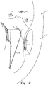
- Figs. 1A-E are schematic illustrations of a mitral valve and a left ventricle being reshaped via a transapical approach
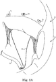
- Figs. 2A-D are schematic illustrations of a mitral valve and a left ventricle being reshaped via a transaortic retrograde approach
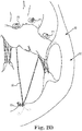
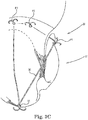
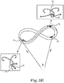
- Figs. 3A-E are schematic illustrations of a mitral valve and a left ventricle being reshaped using clips to anchor a tether to cardiac tissue;
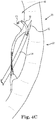
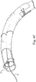
- Figs. 4A-C are schematic illustrations of anchors being applied to a vicinity of the posterior mitral valve leaflet via a transmyocardial approach, in accordance with some applications of the present disclosure
- Figs. 5A-D are schematic illustrations of anchors being applied to a vicinity of the posterior mitral valve leaflet via a transmyocardial approach, in accordance with alternative applications of the present disclosure
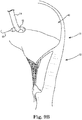
- Figs. 6A-C are schematic illustrations of anchors being applied to a vicinity of the posterior mitral valve leaflet via a transmyocardial approach, in accordance with further alternative applications of the present disclosure
- Fig. 7 is a schematic illustration of anchors being applied to a vicinity of the posterior mitral valve leaflet via a transaortic retrograde transmyocardial approach, in accordance with some applications of the present disclosure
- Figs. 8A-H are schematic illustrations of a mitral ring, self-suturing anchors being disposed inside the mitral ring, using an apparatus of the present invention
- Figs. 9A-I are schematic illustrations of the mitral ring being implanted on the atrial side of the posterior mitral valve, using an apparatus of the present invention.
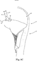
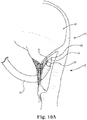
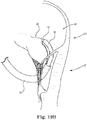
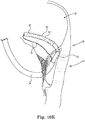
- Figs. 10A-J are schematic illustrations of the mitral ring being implanted on the ventricular side of the posterior mitral valve via a transaortic retrograde approach, in accordance with some applications of the present disclosure.
- Figs. 1A-E are schematic illustrations of a mitral valve 20 and a left ventricle 22 being reshaped via a transapical approach, in accordance with some applications of the present disclosure.
- a P1-anchor P1, a P2-anchor P2, and a P3-anchor P3 are coupled to tissue in the vicinity of, respectively, the P1, P2 and P3 segments of the posterior mitral valve leaflet.
- the clips may be coupled to tissue on, or posterior to the P1, P2, and P3 segments (e.g., to respective locations of the mitral annulus).
- Anchors P1, P2 and P3 typically include any anchors, clips, and/or pledgets, as are known in the art.
- the anchors may include clips that comprise a shape-memory alloy, such as nitinol.
- anchors as described in US 7,056,325 to Makower are used.
- clips e.g., The U-Clip® manufactured by Medtronic (Minneapolis, MN)
- a mitral ring that includes self-suturing clips, as described hereinbelow with reference to Figs.
- a tissue penetrating sheath penetrates the cardiac muscle behind the posterior leaflet, so as to place the anchors on the atrial side of the posterior leaflet, as described in further detail hereinbelow, with reference to Figs. 4-7 .
- the penetrating sheath is inserted via a delivery catheter 24, shown in Fig. 1A , for example.
- a tether 30, which passes through anchors P1, P2, and P3 is pulled and anchored to an anchoring location 32 that is at a cardiac site that is anterior and inferior to the posterior leaflet, e.g., the outside surface of the heart in the vicinity of the apex of the heart, as shown.
- the tether is pulled and anchored to location 32 such that:
- tether 30 is fixedly coupled to anchor P2, e.g., via a knot 34, as shown in Fig. 1D .
- the tether is slidably coupled to the P1 and P3 anchors. For some applications, this results in the P1 and P3 anchors being pulled inferiorly with respect to the P2 anchor, when tether 30 is pulled, as shown in Fig. 1E .
- this restores a saddle-shape to a mitral annulus 36 that has become misshapen due to dilation of the annulus.
- the saddle-shape of the annulus further reduces the circumference of the annulus, and/or reduces tension in the mitral valve leaflets, relative to a flattened mitral annulus.
- tether 30 is pulled through the anchors during a beating heart procedure, such that the degree of functional change can be controlled during the procedure, and observed under functional imaging (e.g., echocardiography).
- functional imaging e.g., echocardiography
- the tether is pulled and anchored in response to the real-time functional imaging, for example, such that an optimal hemodynamic response is achieved.
- FIGs. 2A-D are schematic illustrations of mitral valve 20 and left ventricle 22 being reshaped via a transaortic retrograde approach, in accordance with some applications of the present disclosure.
- anchors P1, P2, and P3, and tether 30 are inserted into the subject's heart via a transaortic retrograde approach.
- the placement of the anchors is generally similar to that described hereinabove, with reference to Figs. 1A-E , except that delivery catheter 24 is inserted via the aorta, rather than via the apex of the heart.
- tether 30 is pulled, and is anchored to anchoring location 32, which may be on the inner surface of the myocardium, for example, in the vicinity of the apex of the heart, as shown in Figs. 2B-D .
- FIGs. 3A-F are schematic illustrations of mitral valve 20 and left ventricle 22 being reshaped, using clips as the P1, P2, and P3 anchors, in accordance with some applications of the present disclosure.
- Fig. 3A-F shows the clips being used in a transaortic retrograde technique, although the clips can also be used in combination with the other techniques described herein, mutatis mutandis.
- delivery catheter 24 inserts the clips into tissue from a ventricular side of the valve.
- the clips are typically inserted such that the clips penetrate the tissue and the tips of the clips enter atrium 40.
- Tether 30 passes through the clips, and the ends of the tether are anchored to anchoring location, as described hereinabove, and as shown in Figs. 3B-D .
- anchor P2 is fixedly coupled to tether 30, e.g., via knot 34, as shown in Fig. 3E .
- the tether is slidably coupled to the P1 and P3 anchors, as indicated by arrow 42 in Fig. 3E .
- anchors P1 and P3 slide toward anchor P2, and are pulled inferiorly with respect to anchor P2.
- clips are inserted from the ventricle into the posterior mitral valve leaflet, such that the clips penetrate the leaflet.
- anchors are placed on the atrial side of the posterior mitral valve leaflet.
- the anchors are placed on the atrial side of the posterior valve leaflet via a transmyocardial approach, in accordance with the techniques described with reference to Figs. 4-7 .
- FIGs. 4A-C are schematic illustrations of anchors P1, P2, and P3 being applied to tissue in the vicinity of the posterior mitral valve leaflet via a transmyocardial approach, in accordance with some applications of the present disclosure.
- a penetrating sheath 50 is inserted into the left ventricle, via delivery catheter 24.
- the penetrating sheath is advanced such that the sheath penetrates the myocardium, and the distal tip of the sheath is disposed in atrium 40, as shown in Fig. 4A .
- an anchor-delivery sheath 52 is advanced out of the distal end of penetrating sheath 50.
- the P1, P2 and P3 anchors are delivered and anchored to atrial tissue that is in the vicinity of (e.g., on or posterior to) the posterior leaflet of the mitral valve, via the anchor-delivery sheath.
- Fig. 4C illustrates the delivery and placement of the P1 anchor via anchor-delivery sheath 52.
- Figs. 5A-D are schematic illustrations of anchors P1, P2, and P3 being applied to tissue in the vicinity of the posterior mitral valve leaflet via a transmyocardial approach, in accordance with alternative applications of the present disclosure.
- penetrating sheath 50 is inserted into left ventricle 22 via anchor-delivery sheath 52, which, in turn, is inserted via delivery catheter 24, as shown in Fig. 5A .
- the penetrating sheath is advanced such that the sheath penetrates the myocardium, and the distal tip of the sheath is disposed in atrium 40, as shown in Fig. 5B .
- Fig. 5C illustrates the delivery and placement of the P1 anchor via anchor-delivery sheath 52.
- Figs. 6A-C are schematic illustrations of anchors P1, P2, and P3 being applied to the posterior mitral valve leaflet via a transmyocardial approach, in accordance with further alternative applications of the present disclosure.
- a single sheath 50 penetrates the myocardium, and delivers the anchors to the tissue of the left atrium.
- penetrating sheath 50 defines openings 54, 56, and 58, via which, respectively, P1, P2, and P3 anchors are delivered.
- the distal tip of the penetrating sheath is advanced from the distal end of delivery catheter 24, such that the penetrating sheath penetrates the myocardium, as shown in the transition from Fig. 6A-6B . Subsequently, the penetrating sheath is advanced, such that opening 54 is facing tissue in the vicinity of the P1 segment of the posterior leaflet of mitral valve 20.
- Anchor P1 is anchored to the aforementioned tissue, via opening 54, as shown in Fig. 6C .
- P2 and P3 anchors are anchored to tissue in the vicinity of, respectively, the P2 and P3 segments of the posterior leaflet of mitral valve 20, via openings 56 and 58 (not shown).
- FIG. 7 is a schematic illustration of anchors P1, P2, and P3 being applied to tissue in the vicinity of the posterior mitral valve leaflet via a transaortic retrograde transmyocardial approach, in accordance with some applications of the present disclosure. It is noted that in the techniques described hereinabove, with reference to Figs. 4-6 , penetrating sheath is inserted into the atrium via a penetration site that is in the vicinity of the anterior commissure of the mitral valve. Anchor-delivery sheath 52 or penetrating sheath 50 is then advanced from the aforementioned penetration site to the P1, P2 and P3 segments of the posterior mitral valve.
- penetrating sheath 50 penetrates the myocardium at a penetrating site that is in the vicinity of the posterior commissure of the mitral valve, as shown in Fig. 7 .
- delivery of the anchors via the penetrating sheath is generally in accordance with the techniques described with reference to Figs. 4-6 .
- Figs. 8A-H are schematic illustrations of a mitral ring 60, self-suturing anchors 62 being disposed inside the mitral ring, using the apparatus of the present invention.
- Mitral ring 60 is typically made of a polymer, a plastic, titanium, stainless steel, and/or other similar materials.
- Anchors 62 are elongate elements that are shaped to define openings 63.
- a mandrel 64 is reversibly disposed through the openings, as shown in Figs. 8A-B .
- ends 66 of the anchors In response to the mandrel being withdrawn from the openings, ends 66 of the anchors automatically move outwardly, via openings 68 in the mitral ring (typically, due to the anchors being elastically loaded), as shown in Fig. 8C .
- the anchors are placed adjacent to tissue that is in the vicinity of the mitral valve (or other tissue as described hereinbelow).
- ends 66 of the anchors move outwardly, thereby entering the tissue. Ends 66 are typically sharp, so as to facilitate penetration of the tissue.
- the anchors in response to mandrel being reinserted via the openings that are defined by the anchors, the anchors exit the tissue via exit routes that are the reverse of the entry routes of the anchors.
- a guidewire 65 passes through openings 63, and the mandrel is advanced and withdrawn over the guidewire.
- the guidewire facilitate reinsertion if the mandrel via the openings, if necessary.
- a tether e.g., tether 30 described hereinabove
- mitral ring 60 includes flexible regions 70 between adjacent anchors.
- the function of the flexible regions is described in further detail hereinbelow.
- Figs. 8D, 8E , and 8F show a single anchor, respectively, configured as when the mandrel is inserted through opening 63 ( Fig. 8D , mandrel not shown), configured as when the mandrel is removed from opening 63 ( Fig. 8E ), and disposed inside mitral ring 60 ( Fig. 8F ) . It is noted that even in the configuration shown in Fig. 8E (i.e., as when mandrel 64 has been withdrawn), the anchor defines an opening 63, via which the mandrel can be reinserted.
- Figs. 8G-H are schematic illustrations that demonstrate the principle by which self-suturing anchors operate.
- Each anchor is configured such that when mandrel 64 is inserted via opening 63, the anchor is elastically loaded, i.e., it is as if there was a loaded spring 72 (shown in dashed lines in Figs. 8G-H ) disposed above the anchor.
- the spring is prevented from expanding by the mandrel.
- the spring Upon removal of the mandrel from opening, the spring is released, thereby causing the diameter of opening 63 to decrease, and pushing ends 66 outward.
- the anchors comprise a shape-memory alloy, such as nitinol.
- Each anchor is shaped in the closed configuration of the anchor.
- the mandrel is inserted through the opening in the anchor, such that the shape-memory alloy is biased open.
- insertion of the mandrel through the opening causes the anchor to become elastically loaded.
- the anchor Upon removal of the mandrel from the opening of the anchor, the anchor reverts to the closed shape thereof.
- the anchors comprise a metal, such as stainless steel.
- Each anchor is shaped into the closed configuration of the anchor and becomes elastically loaded due to the insertion of the mandrel through the opening in the anchor, as described hereinabove.
- Figs. 9A-I are schematic illustrations of mitral ring 60 being implanted on the atrial side of the posterior mitral valve, in accordance with some applications of the present disclosure.
- mitral ring is inserted into left atrium 40 via delivery catheter 24 ( Fig. 9A ), via the inter-atrial septum, as shown.
- the mitral ring is inserted directly into the atrium (e.g., via a minimally invasive surgical approach).
- the most distal of self suturing anchors 62 of ring 60 is placed adjacent to tissue in the vicinity of (e.g., on or posterior to) the P3 segment of the posterior mitral valve leaflet ( Fig. 9B ).
- Mandrel 64 is withdrawn from opening 63 defined by the distal self-suturing anchor, such that the anchor automatically becomes anchored to the tissue, due the ends of the anchors penetrating the tissue, as described hereinabove ( Fig. 9C ).
- a second one of self suturing anchors 62 of ring 60 is placed adjacent to tissue in the vicinity of (e.g., on or posterior to) the P2 segment of the posterior mitral valve leaflet ( Fig. 9D ).
- Mandrel 64 is withdrawn from opening 63 defined by the self-suturing anchor, such that the anchor automatically becomes anchored to the tissue, due the ends of the anchors penetrating the tissue, as described hereinabove ( Fig. 9E ) .
- a third one of self suturing anchors 62 of ring 60 is placed adjacent to tissue in the vicinity of (e.g., on or posterior to) the P1 segment of the posterior mitral valve leaflet ( Fig. 9F ).
- Mandrel 64 is withdrawn from opening 63 defined by the self-suturing anchor, such that the anchor automatically becomes anchored to the tissue, due the ends of the anchors penetrating the tissue, as described hereinabove ( Fig. 9G ).
- a tether 80 passes through the anchors, and is tied to mitral ring 60 in a vicinity of a first end 82 of the ring that is closest to the posterior commissure.
- the tether is tightened, so as to pull the anchors toward each other ( Fig. 9H ).
- the tether is then anchored in its tightened configuration, for example, by tying the tether to a second end 84 of the mitral ring that is closest to the anterior commissure ( Fig. 9I ).
- Flexible regions 70 of the mitral ring facilitate the movement of the anchors toward each other, in response to the tightening of tether 80, by flexing, and/or by becoming compressed.
- the tightening of the tether causes a decrease in the circumference of the mitral annulus.
- mitral ring 60 is placed on the atrial aspect of the posterior mitral valve, as described with reference to Figs. 9A-I , and is combined with the techniques described hereinabove, with reference to Figs. 1-7 , for tethering the posterior leaflet to anchoring location 32, which is at a cardiac site that is anterior and inferior to the posterior leaflet.
- Figs. 10A-J are schematic illustrations of mitral ring 60 being implanted on the ventricular side of the posterior mitral valve via a transaortic retrograde approach, in accordance with some applications of the present disclosure. It is noted that although the mitral ring is shown as being delivered via a transaortic retrograde approach (via delivery catheter 24), for some applications, the mitral ring is delivered to the ventricular side of the posterior mitral valve via a transapical approach.
- the mitral ring is passed along the groove between the posterior mitral valve leaflet and the left ventricular wall, such that first end 82 of the mitral ring is in the vicinity of the posterior commissure of the mitral valve, as shown in Fig. 10A-C . It is noted, for some applications, as shown, a first end of tether 30 passes out of the first end of the mitral ring.
- the mitral ring is placed such that first, second, and third self-suturing anchors 62 are adjacent to tissue in the vicinity of (e.g., on or posterior to) the P3, P2, and P1 segments of the posterior mitral valve leaflet.
- Mandrel 64 is withdrawn from the openings defined by self-suturing anchors, such that the anchors become anchored to the tissue and act as P1, P2, and P3 anchors, in accordance with the techniques described hereinabove, and as shown in Figs. 10D-F .
- Fig. 10G anchoring location 32
- Tether 30 is tightened and anchored to anchoring location 32, in accordance with the techniques described hereinabove, as shown in Figs. 10H-J .
- flexible regions 70 of the mitral ring facilitate flexing and compression of the mitral ring, such that the anchors are able to move toward each other, and such that the P1 and P3 anchors are able to move inferiorly, relative to the P2 anchor.
- self-suturing anchors 62 and ring 60 are described hereinabove as being anchored to tissue associated with the mitral valve, the scope of the present invention includes anchoring self-suturing anchors (and, optionally, a housing) to natural or prosthetic tissue of other portions of a subject's body, mutatis mutandis.
- the anchors may anchor a ring to tissue of a subject's gastrointestinal tract.
- the anchors and the ring are anchored to tissue in the vicinity of the sphincter muscles that are at the junction between the esophagus and the stomach and the ring is tightened in accordance with the techniques described hereinabove, e.g., in order to treat gastroesophageal reflux disease (GERD).
- the anchors anchor a ring to the inside of a subject's stomach, and the ring is tightened in accordance with the techniques described hereinabove, in order to treat obesity.
- the anchors may be used to treat an atrial or a ventricular septal defect, to close a patent foramen ovale, and/or to treat an abdominal aortic aneurysm.
Landscapes
- Health & Medical Sciences (AREA)
- Life Sciences & Earth Sciences (AREA)
- Cardiology (AREA)
- Surgery (AREA)
- General Health & Medical Sciences (AREA)
- Public Health (AREA)
- Heart & Thoracic Surgery (AREA)
- Veterinary Medicine (AREA)
- Biomedical Technology (AREA)
- Animal Behavior & Ethology (AREA)
- Engineering & Computer Science (AREA)
- Molecular Biology (AREA)
- Medical Informatics (AREA)
- Nuclear Medicine, Radiotherapy & Molecular Imaging (AREA)
- Oral & Maxillofacial Surgery (AREA)
- Transplantation (AREA)
- Vascular Medicine (AREA)
- Rheumatology (AREA)
- Prostheses (AREA)
- Surgical Instruments (AREA)
Claims (10)
- Appareil, comprenant :une pluralité d'éléments d'ancrage (62) ;un mandrin (64) qui peut être disposé de manière réversible à travers les éléments d'ancrage (62),chacun des éléments d'ancrage (62) étant configuré pour :s'ancrer automatiquement à un tissu d'un sujet, en pénétrant dans le tissu par l'intermédiaire d'une voie d'entrée, en réponse à un retrait du mandrin (64) de l'élément d'ancrage ; etpar la suite, sortir automatiquement du tissu par l'intermédiaire d'une voie de sortie qui est un inverse de la voie d'entrée, en réponse à une réinsertion du mandrin (64) à travers l'élément d'ancrage.
- Appareil selon la revendication 1, dans lequel les extrémités des éléments d'ancrage (62) sont effilées.
- Appareil selon la revendication 1, dans lequel chacun des éléments d'ancrage (62) comprend un élément allongé qui est incurvé pour définir une ouverture, dans lequel le mandrin (64) peut être disposé de manière réversible à travers les ouvertures (63), et dans lequel des extrémités d'éléments d'ancrage respectifs (62) sont configurées pour s'ancrer automatiquement aux emplacements respectifs du tissu par un déplacement vers l'extérieur, en réponse au retrait du mandrin (64) des ouvertures (63).
- Appareil selon la revendication 3 ; dans lequel les éléments d'ancrage (62) sont configurés de telle sorte que, en réponse au retrait du mandrin (64) des ouvertures (63), des extrémités des éléments d'ancrage (62) se déplacent automatiquement vers l'extérieur, et les diamètres des ouvertures (63) diminuent, du fait d'une charge élastique des éléments d'ancrage (62).
- Appareil selon la revendication 1, dans lequel les éléments d'ancrage (62) sont disposés dans un logement, et dans lequel les éléments d'ancrage sont configurés pour coupler le logement au tissu en s'ancrant au tissu.
- Appareil selon la revendication 5, dans lequel le logement comprend des parties flexibles de celui-ci, les parties flexibles étant disposées entre des éléments d'ancrage adjacents (62) parmi les éléments d'ancrage.
- Appareil selon la revendication 1, dans lequel les éléments d'ancrage (62) comprennent un ancrage P1, un ancrage P2 et un ancrage P3 configurés pour se coupler à un tissu dans un voisinage, respectivement, des segments P1, P2 et P3 d'un feuillet postérieur de la valvule mitrale.
- Appareil selon la revendication 7, dans lequel l'appareil comprend en outre un fil configuré pour passer à travers les ancrages.
- Appareil selon la revendication 8 ; dans lequel le fil est couplé fixement à l'ancrage P2 et est couplé de manière coulissante à l'ancrage P1 et à l'ancrage P3.
- Appareil selon la revendication 8 ; dans lequel l'appareil comprend en outre un ancrage de site cardiaque configuré pour ancrer des extrémités du fil à un site cardiaque d'un cœur d'un sujet.
Applications Claiming Priority (2)
| Application Number | Priority Date | Filing Date | Title |
|---|---|---|---|
| US13/038,040 US8454656B2 (en) | 2011-03-01 | 2011-03-01 | Self-suturing anchors |
| PCT/US2012/027127 WO2012118894A2 (fr) | 2011-03-01 | 2012-02-29 | Ancrages à sutures automatiques |
Publications (2)
| Publication Number | Publication Date |
|---|---|
| EP2680757A2 EP2680757A2 (fr) | 2014-01-08 |
| EP2680757B1 true EP2680757B1 (fr) | 2019-12-11 |
Family
ID=45852721
Family Applications (1)
| Application Number | Title | Priority Date | Filing Date |
|---|---|---|---|
| EP12709431.6A Active EP2680757B1 (fr) | 2011-03-01 | 2012-02-29 | Ancrages à sutures automatiques |
Country Status (3)
| Country | Link |
|---|---|
| US (4) | US8454656B2 (fr) |
| EP (1) | EP2680757B1 (fr) |
| WO (1) | WO2012118894A2 (fr) |
Cited By (1)
| Publication number | Priority date | Publication date | Assignee | Title |
|---|---|---|---|---|
| US12514576B2 (en) | 2024-04-02 | 2026-01-06 | inQB8 Medical Technologies, LLC | Catheter-based methods for remodeling a heart chamber |
Families Citing this family (95)
| Publication number | Priority date | Publication date | Assignee | Title |
|---|---|---|---|---|
| CA2978267A1 (fr) | 2007-08-23 | 2009-02-23 | Dfm, Llc | Procedes de traitement de patients pediatriques a l'aide de dexmedetomidine |
| DE102007043830A1 (de) | 2007-09-13 | 2009-04-02 | Lozonschi, Lucian, Madison | Herzklappenstent |
| WO2011072084A2 (fr) | 2009-12-08 | 2011-06-16 | Avalon Medical Ltd. | Dispositif et système de remplacement de valvule mitrale transcathéter |
| US9603708B2 (en) | 2010-05-19 | 2017-03-28 | Dfm, Llc | Low crossing profile delivery catheter for cardiovascular prosthetic implant |
| US9579193B2 (en) * | 2010-09-23 | 2017-02-28 | Transmural Systems Llc | Methods and systems for delivering prostheses using rail techniques |
| CA3035048C (fr) | 2010-12-23 | 2021-05-04 | Mark Deem | Systeme de reparation et remplacement de valvule mitrale |
| US8454656B2 (en) * | 2011-03-01 | 2013-06-04 | Medtronic Ventor Technologies Ltd. | Self-suturing anchors |
| CN107496054B (zh) | 2011-06-21 | 2020-03-03 | 托尔福公司 | 人工心脏瓣膜装置及相关系统和方法 |
| EP3395298B1 (fr) | 2011-06-27 | 2024-12-18 | University of Maryland, Baltimore | Dispositif de réparation de valvule mitrale transapicale |
| EP3705090B1 (fr) | 2011-08-11 | 2023-12-06 | Tendyne Holdings, Inc. | Améliorations apportées à des valves prothétiques et inventions associées |
| AU2012315597B2 (en) * | 2011-09-30 | 2016-01-07 | Bioventrix, Inc. | Trans-catheter ventricular reconstruction structures, methods, and systems for treatment of congestive heart failure and other conditions |
| US11202704B2 (en) | 2011-10-19 | 2021-12-21 | Twelve, Inc. | Prosthetic heart valve devices, prosthetic mitral valves and associated systems and methods |
| US10016271B2 (en) | 2011-10-19 | 2018-07-10 | Twelve, Inc. | Prosthetic heart valve devices, prosthetic mitral valves and associated systems and methods |
| US9763780B2 (en) | 2011-10-19 | 2017-09-19 | Twelve, Inc. | Devices, systems and methods for heart valve replacement |
| US9039757B2 (en) | 2011-10-19 | 2015-05-26 | Twelve, Inc. | Prosthetic heart valve devices, prosthetic mitral valves and associated systems and methods |
| US9655722B2 (en) | 2011-10-19 | 2017-05-23 | Twelve, Inc. | Prosthetic heart valve devices, prosthetic mitral valves and associated systems and methods |
| JP6151705B2 (ja) | 2011-10-19 | 2017-06-21 | トゥエルヴ, インコーポレイテッド | 心臓弁置換のためのデバイス、システムおよび方法 |
| US9827092B2 (en) | 2011-12-16 | 2017-11-28 | Tendyne Holdings, Inc. | Tethers for prosthetic mitral valve |
| CA2900930A1 (fr) | 2012-02-13 | 2013-08-22 | Mitraspan, Inc. | Procede et appareil de reparation d'une valvule mitrale |
| US10076414B2 (en) | 2012-02-13 | 2018-09-18 | Mitraspan, Inc. | Method and apparatus for repairing a mitral valve |
| US9579198B2 (en) | 2012-03-01 | 2017-02-28 | Twelve, Inc. | Hydraulic delivery systems for prosthetic heart valve devices and associated methods |
| US9445897B2 (en) | 2012-05-01 | 2016-09-20 | Direct Flow Medical, Inc. | Prosthetic implant delivery device with introducer catheter |
| US10004600B2 (en) | 2012-05-02 | 2018-06-26 | Renzo Cecere | Device for soft tissue support and method for anchoring |
| WO2014022124A1 (fr) | 2012-07-28 | 2014-02-06 | Tendyne Holdings, Inc. | Conceptions multi-composantes améliorées pour dispositif de récupération de valve cardiaque, structures d'étanchéité et ensemble stent |
| US9675454B2 (en) | 2012-07-30 | 2017-06-13 | Tendyne Holdings, Inc. | Delivery systems and methods for transcatheter prosthetic valves |
| US11224510B2 (en) | 2013-04-02 | 2022-01-18 | Tendyne Holdings, Inc. | Prosthetic heart valve and systems and methods for delivering the same |
| US10463489B2 (en) | 2013-04-02 | 2019-11-05 | Tendyne Holdings, Inc. | Prosthetic heart valve and systems and methods for delivering the same |
| US10478293B2 (en) | 2013-04-04 | 2019-11-19 | Tendyne Holdings, Inc. | Retrieval and repositioning system for prosthetic heart valve |
| EP2999435B1 (fr) | 2013-05-20 | 2022-12-21 | Twelve, Inc. | Dispositifs de valvule cardiaque pouvant être implantée, dispositifs de réparation de valve mitrale, et systèmes associés |
| US9610159B2 (en) | 2013-05-30 | 2017-04-04 | Tendyne Holdings, Inc. | Structural members for prosthetic mitral valves |
| AU2014302505B2 (en) | 2013-06-25 | 2019-11-28 | Tendyne Holdings, Inc. | Thrombus management and structural compliance features for prosthetic heart valves |
| WO2015017689A1 (fr) | 2013-08-01 | 2015-02-05 | Robert Vidlund | Dispositifs et procédés d'ancrage épicardique |
| WO2015058039A1 (fr) | 2013-10-17 | 2015-04-23 | Robert Vidlund | Appareil et procedes d'alignement et de deploiement de dispositifs intracardiaques |
| EP3062744B1 (fr) | 2013-10-28 | 2020-01-22 | Tendyne Holdings, Inc. | Valvule cardiaque prothétique et ses systèmes de pose |
| US9526611B2 (en) | 2013-10-29 | 2016-12-27 | Tendyne Holdings, Inc. | Apparatus and methods for delivery of transcatheter prosthetic valves |
| US9681864B1 (en) | 2014-01-03 | 2017-06-20 | Harpoon Medical, Inc. | Method and apparatus for transapical procedures on a mitral valve |
| WO2015120122A2 (fr) | 2014-02-05 | 2015-08-13 | Robert Vidlund | Appareil et procédés pour la mise en place d'une valve mitrale prothétique par l'artère fémorale |
| US9986993B2 (en) | 2014-02-11 | 2018-06-05 | Tendyne Holdings, Inc. | Adjustable tether and epicardial pad system for prosthetic heart valve |
| US9993240B2 (en) | 2014-02-12 | 2018-06-12 | Roy H. Trawick | Meniscal repair device |
| AU2015229708B2 (en) | 2014-03-10 | 2019-08-15 | Tendyne Holdings, Inc. | Devices and methods for positioning and monitoring tether load for prosthetic mitral valve |
| CN107405195B (zh) | 2015-01-07 | 2020-09-08 | 坦迪尼控股股份有限公司 | 人造二尖瓣以及用于递送人造二尖瓣的设备和方法 |
| ES2877699T3 (es) | 2015-02-05 | 2021-11-17 | Tendyne Holdings Inc | Válvula cardiaca protésica con ligación y almohadilla epicárdica expandible |
| EP3283010B1 (fr) | 2015-04-16 | 2020-06-17 | Tendyne Holdings, Inc. | Appareil de mise en place et de repositionnement de valvules prothétiques transcathéter |
| CN107920895B (zh) | 2015-08-21 | 2020-06-26 | 托尔福公司 | 可植入心脏瓣膜装置、二尖瓣修复装置以及相关系统和方法 |
| US10327894B2 (en) | 2015-09-18 | 2019-06-25 | Tendyne Holdings, Inc. | Methods for delivery of prosthetic mitral valves |
| WO2017059426A1 (fr) | 2015-10-02 | 2017-04-06 | Harpoon Medical, Inc. | Appareil et procédés d'ancrage distal pour réparation de valvule mitrale |
| CN109152573B (zh) | 2015-10-02 | 2021-04-13 | 哈珀恩医疗有限公司 | 用于二尖瓣修复的远侧锚固件设备和方法 |
| CN108289736B (zh) * | 2015-10-21 | 2020-10-16 | 核心医疗股份公司 | 用于心脏瓣膜修复的医疗设备和方法 |
| EP4309628A3 (fr) | 2015-12-03 | 2024-04-10 | Tendyne Holdings, Inc. | Éléments de cadre pour valvules mitrales prothétiques |
| WO2017117109A1 (fr) | 2015-12-28 | 2017-07-06 | Tendyne Holdings, Inc. | Fermetures de poche auriculaire pour valvules cardiaques prothétiques |
| US11833034B2 (en) | 2016-01-13 | 2023-12-05 | Shifamed Holdings, Llc | Prosthetic cardiac valve devices, systems, and methods |
| US10624743B2 (en) | 2016-04-22 | 2020-04-21 | Edwards Lifesciences Corporation | Beating-heart mitral valve chordae replacement |
| CN116172753A (zh) | 2016-04-29 | 2023-05-30 | 美敦力瓦斯科尔勒公司 | 具有带系绳的锚定件的假体心脏瓣膜设备以及相关联的系统和方法 |
| US10470877B2 (en) | 2016-05-03 | 2019-11-12 | Tendyne Holdings, Inc. | Apparatus and methods for anterior valve leaflet management |
| US20200146854A1 (en) | 2016-05-16 | 2020-05-14 | Elixir Medical Corporation | Methods and devices for heart valve repair |
| WO2017218375A1 (fr) | 2016-06-13 | 2017-12-21 | Tendyne Holdings, Inc. | Administration séquentielle de valvule mitrale prothétique en deux parties |
| EP3478224B1 (fr) | 2016-06-30 | 2022-11-02 | Tendyne Holdings, Inc. | Valves cardiaques prothétiques et appareil associés de mise en place |
| WO2018013515A1 (fr) | 2016-07-12 | 2018-01-18 | Tendyne Holdings, Inc. | Appareil et procédés de récupération transseptale de valvules cardiaques prothétiques |
| US10765515B2 (en) | 2017-04-06 | 2020-09-08 | University Of Maryland, Baltimore | Distal anchor apparatus and methods for mitral valve repair |
| US10575950B2 (en) | 2017-04-18 | 2020-03-03 | Twelve, Inc. | Hydraulic systems for delivering prosthetic heart valve devices and associated methods |
| US10433961B2 (en) | 2017-04-18 | 2019-10-08 | Twelve, Inc. | Delivery systems with tethers for prosthetic heart valve devices and associated methods |
| US10702378B2 (en) | 2017-04-18 | 2020-07-07 | Twelve, Inc. | Prosthetic heart valve device and associated systems and methods |
| US10792151B2 (en) | 2017-05-11 | 2020-10-06 | Twelve, Inc. | Delivery systems for delivering prosthetic heart valve devices and associated methods |
| US10646338B2 (en) | 2017-06-02 | 2020-05-12 | Twelve, Inc. | Delivery systems with telescoping capsules for deploying prosthetic heart valve devices and associated methods |
| US10709591B2 (en) | 2017-06-06 | 2020-07-14 | Twelve, Inc. | Crimping device and method for loading stents and prosthetic heart valves |
| US11026672B2 (en) | 2017-06-19 | 2021-06-08 | Harpoon Medical, Inc. | Method and apparatus for cardiac procedures |
| US12514577B2 (en) | 2017-06-19 | 2026-01-06 | Harpoon Medical, Inc. | Apparatus for approximating sutures in cardiac procedures |
| US10786352B2 (en) | 2017-07-06 | 2020-09-29 | Twelve, Inc. | Prosthetic heart valve devices and associated systems and methods |
| US10729541B2 (en) | 2017-07-06 | 2020-08-04 | Twelve, Inc. | Prosthetic heart valve devices and associated systems and methods |
| WO2019014473A1 (fr) | 2017-07-13 | 2019-01-17 | Tendyne Holdings, Inc. | Valves cardiaques prothétiques et appareil et procédés associés de mise en place |
| AU2018323900A1 (en) | 2017-08-28 | 2020-02-27 | Tendyne Holdings, Inc. | Prosthetic heart valves with tether coupling features |
| US11065120B2 (en) | 2017-10-24 | 2021-07-20 | University Of Maryland, Baltimore | Method and apparatus for cardiac procedures |
| US11285003B2 (en) | 2018-03-20 | 2022-03-29 | Medtronic Vascular, Inc. | Prolapse prevention device and methods of use thereof |
| US11026791B2 (en) | 2018-03-20 | 2021-06-08 | Medtronic Vascular, Inc. | Flexible canopy valve repair systems and methods of use |
| US11517435B2 (en) | 2018-05-04 | 2022-12-06 | Edwards Lifesciences Corporation | Ring-based prosthetic cardiac valve |
| JP7421546B2 (ja) | 2018-08-21 | 2024-01-24 | シファメド・ホールディングス・エルエルシー | 人工心弁デバイス、システム、および方法 |
| US10912644B2 (en) | 2018-10-05 | 2021-02-09 | Shifamed Holdings, Llc | Prosthetic cardiac valve devices, systems, and methods |
| US20200113570A1 (en) * | 2018-10-11 | 2020-04-16 | Moises Jacobs | Gastroesophageal reflux treatment system, method, and device |
| JP7489975B2 (ja) | 2018-10-19 | 2024-05-24 | シファメド・ホールディングス・エルエルシー | 調整可能な医療デバイス |
| CN113543727B (zh) | 2019-02-12 | 2024-11-01 | 爱德华兹生命科学公司 | 受控的组织锚定件间隔 |
| EP4505968A3 (fr) | 2019-03-19 | 2025-05-07 | Shifamed Holdings, LLC | Dispositifs de valvule cardiaque prothétique, systèmes |
| EP3831343B1 (fr) | 2019-12-05 | 2024-01-31 | Tendyne Holdings, Inc. | Ancrage tressé pour valvule mitrale |
| US11648114B2 (en) | 2019-12-20 | 2023-05-16 | Tendyne Holdings, Inc. | Distally loaded sheath and loading funnel |
| US20230105492A1 (en) * | 2020-03-03 | 2023-04-06 | Shifamed Holdings, Llc | Prosthetic cardiac valve devices, systems, and methods |
| US11951002B2 (en) | 2020-03-30 | 2024-04-09 | Tendyne Holdings, Inc. | Apparatus and methods for valve and tether fixation |
| EP4138680B1 (fr) | 2020-04-22 | 2024-12-18 | Edwards Lifesciences Corporation | Mise sous tension régulée de suture |
| CN111616838A (zh) * | 2020-06-30 | 2020-09-04 | 上海市东方医院(同济大学附属东方医院) | 左室假腱索植入系统 |
| WO2022039853A1 (fr) | 2020-08-19 | 2022-02-24 | Tendyne Holdings, Inc. | Tampon apical entièrement transseptal doté d'une poulie pour la mise sous tension |
| EP4203860A4 (fr) | 2020-08-31 | 2024-10-09 | Shifamed Holdings, LLC | Système de pose d'implant prothétique |
| WO2022055923A1 (fr) | 2020-09-10 | 2022-03-17 | Edwards Lifesciences Corporation | Fermeture d'ouvertures de tissu |
| JP7796123B2 (ja) * | 2020-10-27 | 2026-01-08 | エドワーズ ライフサイエンシーズ イノベーション (イスラエル) リミテッド | 心臓の開口部または空洞の面積低減および閉鎖のための装置および方法 |
| JP7835754B2 (ja) | 2020-12-04 | 2026-03-25 | シファメド・ホールディングス・エルエルシー | 張り出し人工心弁送達デバイスおよびシステム |
| US12458498B2 (en) | 2021-02-10 | 2025-11-04 | Edwards Lifesciences Corporation | Implanting grafts to valve leaflets for cardiac procedures |
| US12201521B2 (en) | 2021-03-22 | 2025-01-21 | Shifamed Holdings, Llc | Anchor position verification for prosthetic cardiac valve devices |
| US12502170B2 (en) | 2022-06-23 | 2025-12-23 | Edwards Lifesciences Corporation | Trigger-based tissue anchor deployment |
Family Cites Families (96)
| Publication number | Priority date | Publication date | Assignee | Title |
|---|---|---|---|---|
| US6071292A (en) | 1997-06-28 | 2000-06-06 | Transvascular, Inc. | Transluminal methods and devices for closing, forming attachments to, and/or forming anastomotic junctions in, luminal anatomical structures |
| EP1009332A2 (fr) | 1997-09-04 | 2000-06-21 | Endocore, Inc. | Remplacement de cordages artificiels |
| US6149669A (en) * | 1997-10-30 | 2000-11-21 | Li Medical Technologies, Inc. | Surgical fastener assembly method of use |
| US6332893B1 (en) | 1997-12-17 | 2001-12-25 | Myocor, Inc. | Valve to myocardium tension members device and method |
| CA2620783C (fr) * | 1999-04-09 | 2011-04-05 | Evalve, Inc. | Procede et dispositif de reparation de valvule cardiaque |
| US6626899B2 (en) * | 1999-06-25 | 2003-09-30 | Nidus Medical, Llc | Apparatus and methods for treating tissue |
| SE514718C2 (sv) | 1999-06-29 | 2001-04-09 | Jan Otto Solem | Anordning för behandling av bristande tillslutningsförmåga hos mitralisklaffapparaten |
| US7192442B2 (en) | 1999-06-30 | 2007-03-20 | Edwards Lifesciences Ag | Method and device for treatment of mitral insufficiency |
| US6997951B2 (en) | 1999-06-30 | 2006-02-14 | Edwards Lifesciences Ag | Method and device for treatment of mitral insufficiency |
| US7296577B2 (en) | 2000-01-31 | 2007-11-20 | Edwards Lifescience Ag | Transluminal mitral annuloplasty with active anchoring |
| US6989028B2 (en) | 2000-01-31 | 2006-01-24 | Edwards Lifesciences Ag | Medical system and method for remodeling an extravascular tissue structure |
| US6524338B1 (en) * | 2000-08-25 | 2003-02-25 | Steven R. Gundry | Method and apparatus for stapling an annuloplasty band in-situ |
| US6602288B1 (en) | 2000-10-05 | 2003-08-05 | Edwards Lifesciences Corporation | Minimally-invasive annuloplasty repair segment delivery template, system and method of use |
| US6723038B1 (en) | 2000-10-06 | 2004-04-20 | Myocor, Inc. | Methods and devices for improving mitral valve function |
| US6810882B2 (en) * | 2001-01-30 | 2004-11-02 | Ev3 Santa Rosa, Inc. | Transluminal mitral annuloplasty |
| WO2002062263A2 (fr) * | 2001-02-05 | 2002-08-15 | Viacor, Inc. | Appareil et procede permettant de diminuer la regurgitation mitrale |
| US7037334B1 (en) | 2001-04-24 | 2006-05-02 | Mitralign, Inc. | Method and apparatus for catheter-based annuloplasty using local plications |
| US20060069429A1 (en) * | 2001-04-24 | 2006-03-30 | Spence Paul A | Tissue fastening systems and methods utilizing magnetic guidance |
| US20060052821A1 (en) | 2001-09-06 | 2006-03-09 | Ovalis, Inc. | Systems and methods for treating septal defects |
| US6776784B2 (en) | 2001-09-06 | 2004-08-17 | Core Medical, Inc. | Clip apparatus for closing septal defects and methods of use |
| US6702835B2 (en) | 2001-09-07 | 2004-03-09 | Core Medical, Inc. | Needle apparatus for closing septal defects and methods for using such apparatus |
| US20050267495A1 (en) | 2004-05-17 | 2005-12-01 | Gateway Medical, Inc. | Systems and methods for closing internal tissue defects |
| US20030050693A1 (en) * | 2001-09-10 | 2003-03-13 | Quijano Rodolfo C. | Minimally invasive delivery system for annuloplasty rings |
| US20050177180A1 (en) | 2001-11-28 | 2005-08-11 | Aptus Endosystems, Inc. | Devices, systems, and methods for supporting tissue and/or structures within a hollow body organ |
| WO2003053289A1 (fr) * | 2001-12-21 | 2003-07-03 | Simcha Milo | Systeme d'implantation d'anneaux d'annuloplastie |
| US6764510B2 (en) * | 2002-01-09 | 2004-07-20 | Myocor, Inc. | Devices and methods for heart valve treatment |
| WO2003059152A2 (fr) | 2002-01-14 | 2003-07-24 | Nmt Medical, Inc. | Procede et dispositif de fermeture d'une persistance du foramen ovale |
| US7048754B2 (en) * | 2002-03-01 | 2006-05-23 | Evalve, Inc. | Suture fasteners and methods of use |
| US20040243227A1 (en) * | 2002-06-13 | 2004-12-02 | Guided Delivery Systems, Inc. | Delivery devices and methods for heart valve repair |
| US7753924B2 (en) | 2003-09-04 | 2010-07-13 | Guided Delivery Systems, Inc. | Delivery devices and methods for heart valve repair |
| US8287555B2 (en) | 2003-02-06 | 2012-10-16 | Guided Delivery Systems, Inc. | Devices and methods for heart valve repair |
| US7758637B2 (en) | 2003-02-06 | 2010-07-20 | Guided Delivery Systems, Inc. | Delivery devices and methods for heart valve repair |
| EP1530441B1 (fr) | 2002-06-13 | 2017-08-02 | Ancora Heart, Inc. | Dispositifs et procedes de reparation de valvule cardiaque |
| US8641727B2 (en) | 2002-06-13 | 2014-02-04 | Guided Delivery Systems, Inc. | Devices and methods for heart valve repair |
| US7753922B2 (en) | 2003-09-04 | 2010-07-13 | Guided Delivery Systems, Inc. | Devices and methods for cardiac annulus stabilization and treatment |
| US7588582B2 (en) | 2002-06-13 | 2009-09-15 | Guided Delivery Systems Inc. | Methods for remodeling cardiac tissue |
| US7883538B2 (en) * | 2002-06-13 | 2011-02-08 | Guided Delivery Systems Inc. | Methods and devices for termination |
| US20060122633A1 (en) | 2002-06-13 | 2006-06-08 | John To | Methods and devices for termination |
| US7666193B2 (en) | 2002-06-13 | 2010-02-23 | Guided Delivery Sytems, Inc. | Delivery devices and methods for heart valve repair |
| AU2003265354A1 (en) | 2002-08-01 | 2004-02-23 | The General Hospital Corporation | Cardiac devices and methods for minimally invasive repair of ischemic mitral regurgitation |
| US8979923B2 (en) * | 2002-10-21 | 2015-03-17 | Mitralign, Inc. | Tissue fastening systems and methods utilizing magnetic guidance |
| US7335213B1 (en) * | 2002-11-15 | 2008-02-26 | Abbott Cardiovascular Systems Inc. | Apparatus and methods for heart valve repair |
| US7404824B1 (en) * | 2002-11-15 | 2008-07-29 | Advanced Cardiovascular Systems, Inc. | Valve aptation assist device |
| AU2003290979A1 (en) * | 2002-11-15 | 2004-06-15 | The Government Of The United States Of America As Represented By The Secretary Of Health And Human Services | Method and device for catheter-based repair of cardiac valves |
| US6997950B2 (en) | 2003-01-16 | 2006-02-14 | Chawla Surendra K | Valve repair device |
| WO2004069055A2 (fr) | 2003-02-04 | 2004-08-19 | Ev3 Sunnyvale Inc. | Systeme de fermeture du foramen ovale d'un patient |
| WO2005018507A2 (fr) * | 2003-07-18 | 2005-03-03 | Ev3 Santa Rosa, Inc. | Système et procédés d'annuloplastie mitrale activés à distance |
| US7534204B2 (en) | 2003-09-03 | 2009-05-19 | Guided Delivery Systems, Inc. | Cardiac visualization devices and methods |
| WO2005046488A2 (fr) * | 2003-11-12 | 2005-05-26 | Medtronic Vascular, Inc. | Systeme de reduction de l'annulus des valvules cardiaques |
| US20050273138A1 (en) | 2003-12-19 | 2005-12-08 | Guided Delivery Systems, Inc. | Devices and methods for anchoring tissue |
| US7166127B2 (en) | 2003-12-23 | 2007-01-23 | Mitralign, Inc. | Tissue fastening systems and methods utilizing magnetic guidance |
| US8864822B2 (en) | 2003-12-23 | 2014-10-21 | Mitralign, Inc. | Devices and methods for introducing elements into tissue |
| US20050187568A1 (en) | 2004-02-20 | 2005-08-25 | Klenk Alan R. | Devices and methods for closing a patent foramen ovale with a coil-shaped closure device |
| US8206439B2 (en) | 2004-02-23 | 2012-06-26 | International Heart Institute Of Montana Foundation | Internal prosthesis for reconstruction of cardiac geometry |
| US7211110B2 (en) | 2004-12-09 | 2007-05-01 | Edwards Lifesciences Corporation | Diagnostic kit to assist with heart valve annulus adjustment |
| US20100298929A1 (en) * | 2005-02-07 | 2010-11-25 | Thornton Troy L | Methods, systems and devices for cardiac valve repair |
| US20110060407A1 (en) * | 2005-02-07 | 2011-03-10 | Ted Ketai | Methods, systems and devices for cardiac valve repair |
| US8951285B2 (en) | 2005-07-05 | 2015-02-10 | Mitralign, Inc. | Tissue anchor, anchoring system and methods of using the same |
| US20070027533A1 (en) * | 2005-07-28 | 2007-02-01 | Medtronic Vascular, Inc. | Cardiac valve annulus restraining device |
| US20070055206A1 (en) | 2005-08-10 | 2007-03-08 | Guided Delivery Systems, Inc. | Methods and devices for deployment of tissue anchors |
| US7635386B1 (en) | 2006-03-07 | 2009-12-22 | University Of Maryland, Baltimore | Methods and devices for performing cardiac valve repair |
| US7431692B2 (en) | 2006-03-09 | 2008-10-07 | Edwards Lifesciences Corporation | Apparatus, system, and method for applying and adjusting a tensioning element to a hollow body organ |
| US20070244555A1 (en) | 2006-04-12 | 2007-10-18 | Medtronic Vascular, Inc. | Annuloplasty Device Having a Helical Anchor and Methods for its Use |
| EP3593761A1 (fr) | 2006-04-12 | 2020-01-15 | Medtronic Vascular, Inc. | Dispositif d'annuloplastie équipé d'un ancrage hélicoïdal |
| US7699892B2 (en) | 2006-04-12 | 2010-04-20 | Medtronic Vascular, Inc. | Minimally invasive procedure for implanting an annuloplasty device |
| US8932348B2 (en) * | 2006-05-18 | 2015-01-13 | Edwards Lifesciences Corporation | Device and method for improving heart valve function |
| US8834564B2 (en) * | 2006-09-19 | 2014-09-16 | Medtronic, Inc. | Sinus-engaging valve fixation member |
| US8052750B2 (en) * | 2006-09-19 | 2011-11-08 | Medtronic Ventor Technologies Ltd | Valve prosthesis fixation techniques using sandwiching |
| EP2091465B1 (fr) * | 2006-11-14 | 2018-01-31 | The Government of the United States of America as represented by the Secretary of the Department of Health and Human Services | Dispositif de protection de l'artère coronaire et du myocarde |
| US8926695B2 (en) * | 2006-12-05 | 2015-01-06 | Valtech Cardio, Ltd. | Segmented ring placement |
| US9192471B2 (en) * | 2007-01-08 | 2015-11-24 | Millipede, Inc. | Device for translumenal reshaping of a mitral valve annulus |
| US8845723B2 (en) | 2007-03-13 | 2014-09-30 | Mitralign, Inc. | Systems and methods for introducing elements into tissue |
| FR2915087B1 (fr) | 2007-04-20 | 2021-11-26 | Corevalve Inc | Implant de traitement d'une valve cardiaque, en particulier d'une valve mitrale, materiel inculant cet implant et materiel de mise en place de cet implant. |
| US9308086B2 (en) * | 2010-09-21 | 2016-04-12 | Hocor Cardiovascular Technologies Llc | Method and system for balloon counterpulsation during aortic valve replacement |
| DE102007043830A1 (de) * | 2007-09-13 | 2009-04-02 | Lozonschi, Lucian, Madison | Herzklappenstent |
| EP2217153B1 (fr) | 2007-10-19 | 2021-03-03 | Ancora Heart, Inc. | Systèmes pour la remodélisation cardiaque |
| US8597347B2 (en) * | 2007-11-15 | 2013-12-03 | Cardiosolutions, Inc. | Heart regurgitation method and apparatus |
| WO2010070649A1 (fr) * | 2008-12-21 | 2010-06-24 | Mor Research Applications Ltd. | Corps allongé pour son déploiement dans un sinus coronaire |
| JP2011510797A (ja) | 2008-02-06 | 2011-04-07 | ガイデッド デリバリー システムズ, インコーポレイテッド | 多重窓ガイドトンネル |
| EP2259740A2 (fr) | 2008-02-20 | 2010-12-15 | Guided Delivery Systems, Inc. | Système de cathéter d'électrophysiologie |
| FR2930137B1 (fr) | 2008-04-18 | 2010-04-23 | Corevalve Inc | Materiel de traitement d'une valve cardiaque, en particulier d'une valve mitrale. |
| US7972370B2 (en) * | 2008-04-24 | 2011-07-05 | Medtronic Vascular, Inc. | Stent graft system and method of use |
| US20100023056A1 (en) | 2008-07-23 | 2010-01-28 | Guided Delivery Systems Inc. | Tether-anchor assemblies |
| US20100030330A1 (en) * | 2008-08-01 | 2010-02-04 | Edwards Lifesciences Corporation | Device and method for mitral valve repair |
| US8945211B2 (en) | 2008-09-12 | 2015-02-03 | Mitralign, Inc. | Tissue plication device and method for its use |
| WO2010073246A2 (fr) * | 2008-12-22 | 2010-07-01 | Valtech Cardio, Ltd. | Dispositif d'annuloplastie réglable et mécanismes d'ajustement correspondants |
| US8241351B2 (en) * | 2008-12-22 | 2012-08-14 | Valtech Cardio, Ltd. | Adjustable partial annuloplasty ring and mechanism therefor |
| US8911494B2 (en) * | 2009-05-04 | 2014-12-16 | Valtech Cardio, Ltd. | Deployment techniques for annuloplasty ring |
| US8808368B2 (en) | 2008-12-22 | 2014-08-19 | Valtech Cardio, Ltd. | Implantation of repair chords in the heart |
| EP3708123A1 (fr) * | 2009-03-30 | 2020-09-16 | JC Medical, Inc. | Prothèses valvulaires sans suture, dispositifs et procédés d'administration |
| US8277502B2 (en) * | 2009-10-29 | 2012-10-02 | Valtech Cardio, Ltd. | Tissue anchor for annuloplasty device |
| WO2011072084A2 (fr) * | 2009-12-08 | 2011-06-16 | Avalon Medical Ltd. | Dispositif et système de remplacement de valvule mitrale transcathéter |
| US8790394B2 (en) * | 2010-05-24 | 2014-07-29 | Valtech Cardio, Ltd. | Adjustable artificial chordeae tendineae with suture loops |
| GB201011978D0 (en) | 2010-07-15 | 2010-09-01 | Black & Decker Inc | Side handle |
| EP2600799B1 (fr) * | 2010-08-04 | 2017-05-17 | ValCare, Inc. | Réparation des valvules cardiaques par cathétérisme percutané |
| US8454656B2 (en) * | 2011-03-01 | 2013-06-04 | Medtronic Ventor Technologies Ltd. | Self-suturing anchors |
-
2011
- 2011-03-01 US US13/038,040 patent/US8454656B2/en active Active
-
2012
- 2012-02-29 EP EP12709431.6A patent/EP2680757B1/fr active Active
- 2012-02-29 WO PCT/US2012/027127 patent/WO2012118894A2/fr not_active Ceased
-
2013
- 2013-05-14 US US13/894,289 patent/US9345470B2/en active Active
-
2016
- 2016-04-26 US US15/138,789 patent/US10543086B2/en active Active
-
2020
- 2020-01-08 US US16/737,098 patent/US11751993B2/en active Active
Non-Patent Citations (1)
| Title |
|---|
| None * |
Cited By (2)
| Publication number | Priority date | Publication date | Assignee | Title |
|---|---|---|---|---|
| US12514576B2 (en) | 2024-04-02 | 2026-01-06 | inQB8 Medical Technologies, LLC | Catheter-based methods for remodeling a heart chamber |
| US12569243B2 (en) | 2024-04-02 | 2026-03-10 | inQB8 Medical Technologies, LLC | Systems for percutaneous ventriculoplasty using ventricular anchors |
Also Published As
| Publication number | Publication date |
|---|---|
| EP2680757A2 (fr) | 2014-01-08 |
| US9345470B2 (en) | 2016-05-24 |
| US8454656B2 (en) | 2013-06-04 |
| WO2012118894A2 (fr) | 2012-09-07 |
| WO2012118894A3 (fr) | 2012-11-15 |
| US20200138575A1 (en) | 2020-05-07 |
| US11751993B2 (en) | 2023-09-12 |
| US20120226294A1 (en) | 2012-09-06 |
| US10543086B2 (en) | 2020-01-28 |
| US20160310271A1 (en) | 2016-10-27 |
| US20130282060A1 (en) | 2013-10-24 |
Similar Documents
| Publication | Publication Date | Title |
|---|---|---|
| US11751993B2 (en) | Methods of delivering and deploying a heart valve apparatus at a mitral valve | |
| US10098731B2 (en) | Mitral valve repair | |
| US20250107802A1 (en) | Multi-window guide tunnel | |
| US20260096812A1 (en) | Systems and methods for anchoring an implant | |
| US20220192656A1 (en) | Device for heart repair | |
| US10105219B2 (en) | Mitral valve leaflet clip | |
| JP6535369B2 (ja) | 独立型グリッパ | |
| EP2410948B1 (fr) | Dispositifs pour la réparation de valvules cardiaques | |
| US11253360B2 (en) | Low profile tissue anchor for minimally invasive heart valve repair | |
| US10499941B2 (en) | Mitral valve repair devices | |
| US20190343634A1 (en) | Radial arm tissue anchor for minimally invasive heart valve repair | |
| US11452601B2 (en) | Wire annuloplasty ring | |
| US20100185278A1 (en) | Apical Papillary Msucle Attachment for Left Ventricular Reduction | |
| CN115363825A (zh) | 用于新生腱索的经血管植入的方法和设备 | |
| US20110015476A1 (en) | Devices and Methods for Treating Cardiomyopathy | |
| EP1919369A1 (fr) | Dispositifs et procedes d'ancrage de tissu | |
| WO2011047201A2 (fr) | Dispositifs et procédés pour le traitement de cardiomyopathie | |
| CN121512745A (zh) | 用于治疗瓣膜返流的二尖瓣植入物 |
Legal Events
| Date | Code | Title | Description |
|---|---|---|---|
| PUAI | Public reference made under article 153(3) epc to a published international application that has entered the european phase |
Free format text: ORIGINAL CODE: 0009012 |
|
| 17P | Request for examination filed |
Effective date: 20130924 |
|
| AK | Designated contracting states |
Kind code of ref document: A2 Designated state(s): AL AT BE BG CH CY CZ DE DK EE ES FI FR GB GR HR HU IE IS IT LI LT LU LV MC MK MT NL NO PL PT RO RS SE SI SK SM TR |
|
| 17Q | First examination report despatched |
Effective date: 20140711 |
|
| GRAP | Despatch of communication of intention to grant a patent |
Free format text: ORIGINAL CODE: EPIDOSNIGR1 |
|
| STAA | Information on the status of an ep patent application or granted ep patent |
Free format text: STATUS: GRANT OF PATENT IS INTENDED |
|
| RIC1 | Information provided on ipc code assigned before grant |
Ipc: A61F 2/24 20060101ALI20190723BHEP Ipc: A61B 17/064 20060101ALN20190723BHEP Ipc: A61B 17/06 20060101ALN20190723BHEP Ipc: A61B 17/068 20060101ALN20190723BHEP Ipc: A61B 17/00 20060101ALN20190723BHEP Ipc: A61B 17/04 20060101AFI20190723BHEP |
|
| INTG | Intention to grant announced |
Effective date: 20190823 |
|
| GRAS | Grant fee paid |
Free format text: ORIGINAL CODE: EPIDOSNIGR3 |
|
| GRAA | (expected) grant |
Free format text: ORIGINAL CODE: 0009210 |
|
| STAA | Information on the status of an ep patent application or granted ep patent |
Free format text: STATUS: THE PATENT HAS BEEN GRANTED |
|
| AK | Designated contracting states |
Kind code of ref document: B1 Designated state(s): AL AT BE BG CH CY CZ DE DK EE ES FI FR GB GR HR HU IE IS IT LI LT LU LV MC MK MT NL NO PL PT RO RS SE SI SK SM TR |
|
| REG | Reference to a national code |
Ref country code: GB Ref legal event code: FG4D |
|
| REG | Reference to a national code |
Ref country code: CH Ref legal event code: EP |
|
| REG | Reference to a national code |
Ref country code: AT Ref legal event code: REF Ref document number: 1211362 Country of ref document: AT Kind code of ref document: T Effective date: 20191215 |
|
| REG | Reference to a national code |
Ref country code: DE Ref legal event code: R096 Ref document number: 602012066365 Country of ref document: DE |
|
| REG | Reference to a national code |
Ref country code: IE Ref legal event code: FG4D |
|
| REG | Reference to a national code |
Ref country code: NL Ref legal event code: FP |
|
| REG | Reference to a national code |
Ref country code: LT Ref legal event code: MG4D |
|
| PG25 | Lapsed in a contracting state [announced via postgrant information from national office to epo] |
Ref country code: NO Free format text: LAPSE BECAUSE OF FAILURE TO SUBMIT A TRANSLATION OF THE DESCRIPTION OR TO PAY THE FEE WITHIN THE PRESCRIBED TIME-LIMIT Effective date: 20200311 Ref country code: GR Free format text: LAPSE BECAUSE OF FAILURE TO SUBMIT A TRANSLATION OF THE DESCRIPTION OR TO PAY THE FEE WITHIN THE PRESCRIBED TIME-LIMIT Effective date: 20200312 Ref country code: FI Free format text: LAPSE BECAUSE OF FAILURE TO SUBMIT A TRANSLATION OF THE DESCRIPTION OR TO PAY THE FEE WITHIN THE PRESCRIBED TIME-LIMIT Effective date: 20191211 Ref country code: LT Free format text: LAPSE BECAUSE OF FAILURE TO SUBMIT A TRANSLATION OF THE DESCRIPTION OR TO PAY THE FEE WITHIN THE PRESCRIBED TIME-LIMIT Effective date: 20191211 Ref country code: BG Free format text: LAPSE BECAUSE OF FAILURE TO SUBMIT A TRANSLATION OF THE DESCRIPTION OR TO PAY THE FEE WITHIN THE PRESCRIBED TIME-LIMIT Effective date: 20200311 Ref country code: ES Free format text: LAPSE BECAUSE OF FAILURE TO SUBMIT A TRANSLATION OF THE DESCRIPTION OR TO PAY THE FEE WITHIN THE PRESCRIBED TIME-LIMIT Effective date: 20191211 Ref country code: SE Free format text: LAPSE BECAUSE OF FAILURE TO SUBMIT A TRANSLATION OF THE DESCRIPTION OR TO PAY THE FEE WITHIN THE PRESCRIBED TIME-LIMIT Effective date: 20191211 Ref country code: LV Free format text: LAPSE BECAUSE OF FAILURE TO SUBMIT A TRANSLATION OF THE DESCRIPTION OR TO PAY THE FEE WITHIN THE PRESCRIBED TIME-LIMIT Effective date: 20191211 |
|
| PGFP | Annual fee paid to national office [announced via postgrant information from national office to epo] |
Ref country code: IE Payment date: 20200123 Year of fee payment: 9 |
|
| PG25 | Lapsed in a contracting state [announced via postgrant information from national office to epo] |
Ref country code: HR Free format text: LAPSE BECAUSE OF FAILURE TO SUBMIT A TRANSLATION OF THE DESCRIPTION OR TO PAY THE FEE WITHIN THE PRESCRIBED TIME-LIMIT Effective date: 20191211 Ref country code: RS Free format text: LAPSE BECAUSE OF FAILURE TO SUBMIT A TRANSLATION OF THE DESCRIPTION OR TO PAY THE FEE WITHIN THE PRESCRIBED TIME-LIMIT Effective date: 20191211 |
|
| PGFP | Annual fee paid to national office [announced via postgrant information from national office to epo] |
Ref country code: CH Payment date: 20200123 Year of fee payment: 9 |
|
| PG25 | Lapsed in a contracting state [announced via postgrant information from national office to epo] |
Ref country code: AL Free format text: LAPSE BECAUSE OF FAILURE TO SUBMIT A TRANSLATION OF THE DESCRIPTION OR TO PAY THE FEE WITHIN THE PRESCRIBED TIME-LIMIT Effective date: 20191211 |
|
| PG25 | Lapsed in a contracting state [announced via postgrant information from national office to epo] |
Ref country code: CZ Free format text: LAPSE BECAUSE OF FAILURE TO SUBMIT A TRANSLATION OF THE DESCRIPTION OR TO PAY THE FEE WITHIN THE PRESCRIBED TIME-LIMIT Effective date: 20191211 Ref country code: PT Free format text: LAPSE BECAUSE OF FAILURE TO SUBMIT A TRANSLATION OF THE DESCRIPTION OR TO PAY THE FEE WITHIN THE PRESCRIBED TIME-LIMIT Effective date: 20200506 Ref country code: RO Free format text: LAPSE BECAUSE OF FAILURE TO SUBMIT A TRANSLATION OF THE DESCRIPTION OR TO PAY THE FEE WITHIN THE PRESCRIBED TIME-LIMIT Effective date: 20191211 Ref country code: EE Free format text: LAPSE BECAUSE OF FAILURE TO SUBMIT A TRANSLATION OF THE DESCRIPTION OR TO PAY THE FEE WITHIN THE PRESCRIBED TIME-LIMIT Effective date: 20191211 |
|
| PG25 | Lapsed in a contracting state [announced via postgrant information from national office to epo] |
Ref country code: IS Free format text: LAPSE BECAUSE OF FAILURE TO SUBMIT A TRANSLATION OF THE DESCRIPTION OR TO PAY THE FEE WITHIN THE PRESCRIBED TIME-LIMIT Effective date: 20200411 Ref country code: SM Free format text: LAPSE BECAUSE OF FAILURE TO SUBMIT A TRANSLATION OF THE DESCRIPTION OR TO PAY THE FEE WITHIN THE PRESCRIBED TIME-LIMIT Effective date: 20191211 Ref country code: SK Free format text: LAPSE BECAUSE OF FAILURE TO SUBMIT A TRANSLATION OF THE DESCRIPTION OR TO PAY THE FEE WITHIN THE PRESCRIBED TIME-LIMIT Effective date: 20191211 |
|
| REG | Reference to a national code |
Ref country code: DE Ref legal event code: R097 Ref document number: 602012066365 Country of ref document: DE |
|
| REG | Reference to a national code |
Ref country code: AT Ref legal event code: MK05 Ref document number: 1211362 Country of ref document: AT Kind code of ref document: T Effective date: 20191211 |
|
| PLBE | No opposition filed within time limit |
Free format text: ORIGINAL CODE: 0009261 |
|
| STAA | Information on the status of an ep patent application or granted ep patent |
Free format text: STATUS: NO OPPOSITION FILED WITHIN TIME LIMIT |
|
| REG | Reference to a national code |
Ref country code: BE Ref legal event code: MM Effective date: 20200229 |
|
| PG25 | Lapsed in a contracting state [announced via postgrant information from national office to epo] |
Ref country code: LU Free format text: LAPSE BECAUSE OF NON-PAYMENT OF DUE FEES Effective date: 20200229 Ref country code: DK Free format text: LAPSE BECAUSE OF FAILURE TO SUBMIT A TRANSLATION OF THE DESCRIPTION OR TO PAY THE FEE WITHIN THE PRESCRIBED TIME-LIMIT Effective date: 20191211 Ref country code: MC Free format text: LAPSE BECAUSE OF FAILURE TO SUBMIT A TRANSLATION OF THE DESCRIPTION OR TO PAY THE FEE WITHIN THE PRESCRIBED TIME-LIMIT Effective date: 20191211 |
|
| 26N | No opposition filed |
Effective date: 20200914 |
|
| PG25 | Lapsed in a contracting state [announced via postgrant information from national office to epo] |
Ref country code: AT Free format text: LAPSE BECAUSE OF FAILURE TO SUBMIT A TRANSLATION OF THE DESCRIPTION OR TO PAY THE FEE WITHIN THE PRESCRIBED TIME-LIMIT Effective date: 20191211 Ref country code: PL Free format text: LAPSE BECAUSE OF FAILURE TO SUBMIT A TRANSLATION OF THE DESCRIPTION OR TO PAY THE FEE WITHIN THE PRESCRIBED TIME-LIMIT Effective date: 20191211 Ref country code: SI Free format text: LAPSE BECAUSE OF FAILURE TO SUBMIT A TRANSLATION OF THE DESCRIPTION OR TO PAY THE FEE WITHIN THE PRESCRIBED TIME-LIMIT Effective date: 20191211 |
|
| PG25 | Lapsed in a contracting state [announced via postgrant information from national office to epo] |
Ref country code: IT Free format text: LAPSE BECAUSE OF FAILURE TO SUBMIT A TRANSLATION OF THE DESCRIPTION OR TO PAY THE FEE WITHIN THE PRESCRIBED TIME-LIMIT Effective date: 20191211 |
|
| PG25 | Lapsed in a contracting state [announced via postgrant information from national office to epo] |
Ref country code: BE Free format text: LAPSE BECAUSE OF NON-PAYMENT OF DUE FEES Effective date: 20200229 |
|
| GBPC | Gb: european patent ceased through non-payment of renewal fee |
Effective date: 20200311 |
|
| PG25 | Lapsed in a contracting state [announced via postgrant information from national office to epo] |
Ref country code: GB Free format text: LAPSE BECAUSE OF NON-PAYMENT OF DUE FEES Effective date: 20200311 |
|
| PG25 | Lapsed in a contracting state [announced via postgrant information from national office to epo] |
Ref country code: LI Free format text: LAPSE BECAUSE OF NON-PAYMENT OF DUE FEES Effective date: 20210228 Ref country code: CH Free format text: LAPSE BECAUSE OF NON-PAYMENT OF DUE FEES Effective date: 20210228 |
|
| PG25 | Lapsed in a contracting state [announced via postgrant information from national office to epo] |
Ref country code: IE Free format text: LAPSE BECAUSE OF NON-PAYMENT OF DUE FEES Effective date: 20210228 |
|
| PG25 | Lapsed in a contracting state [announced via postgrant information from national office to epo] |
Ref country code: TR Free format text: LAPSE BECAUSE OF FAILURE TO SUBMIT A TRANSLATION OF THE DESCRIPTION OR TO PAY THE FEE WITHIN THE PRESCRIBED TIME-LIMIT Effective date: 20191211 Ref country code: MT Free format text: LAPSE BECAUSE OF FAILURE TO SUBMIT A TRANSLATION OF THE DESCRIPTION OR TO PAY THE FEE WITHIN THE PRESCRIBED TIME-LIMIT Effective date: 20191211 Ref country code: CY Free format text: LAPSE BECAUSE OF FAILURE TO SUBMIT A TRANSLATION OF THE DESCRIPTION OR TO PAY THE FEE WITHIN THE PRESCRIBED TIME-LIMIT Effective date: 20191211 |
|
| PG25 | Lapsed in a contracting state [announced via postgrant information from national office to epo] |
Ref country code: MK Free format text: LAPSE BECAUSE OF FAILURE TO SUBMIT A TRANSLATION OF THE DESCRIPTION OR TO PAY THE FEE WITHIN THE PRESCRIBED TIME-LIMIT Effective date: 20191211 |
|
| PGFP | Annual fee paid to national office [announced via postgrant information from national office to epo] |
Ref country code: NL Payment date: 20250121 Year of fee payment: 14 |
|
| PGFP | Annual fee paid to national office [announced via postgrant information from national office to epo] |
Ref country code: FR Payment date: 20250121 Year of fee payment: 14 |
|
| PGFP | Annual fee paid to national office [announced via postgrant information from national office to epo] |
Ref country code: DE Payment date: 20260121 Year of fee payment: 15 |